JETIR1511020 Journal of Emerging Technologies and Innovative Research (JETIR) www.jetir.org 113
A REVIEW ON COST OPTIMIZATION OF
POWER PRESS BY ANALYSIS OF C-FRAME
USING SOLID WORKS
1Mustafa Telwala, 2Anand Parikh, 3Vaja Hitesh, 4HardikbhaiDabhi, 5
Rajdipsinh. G. Vaghela, 6Hardik N. Chauhan 1,2,3,4
Students, Department of Mech. Engg., 5,6 Asst. Prof., Department of Mech. Engg., Atmiya Institute of Technology & Science, Rajkot.
Abstract— Power press working is defined as chip less manufacturing process. We can also say as cold stamping process. The machine used for press working is known as press. Press has a frame, a bed or bolsters plate and a reciprocating element called ram which exerts force upon work material through special tool mounted on it and bolster. Press works on impact load condition cause that continuous impact load on frame and press machine experience tensile & bending stress also. Press machine continuous deals with stress and because of that frequently structural failure problem occurred in machine. To compensate this failure c-frame has to fulfill certain critical constraints. Software solid works has been used for this analysis with main aim to optimized cost as well as design of c-frame without changing quality of the output. Keywords: C-Frame, FEA, Stress Concentration, solid works, Weight reduction.
____________________________________________________________________________________________________
I. Introduction:
Press are used for making large quantities parts quickly, accurately and economically from the cold working of mild steel and other ductile materials. Now-a-days practice is to produce most of the sheet parts of any shape by using specially designed press tools and other combination of operations by applying pressure Since the software evaluation, there has been continues up gradation of design and analyzed different parameters of frame of power press machines by using various methods like FEA.
II. Power press working:
We know that there are mainly three types of power presses: mechanical, hydraulic, and pneumatic. Their control systems may be mechanical or electro-mechanical. Through these three major types of power presses share some common features, the mechanical power press is the most commonly used and researched. In power press two major are stationary bed and a moving ram. Mechanical power press works on the principle of reciprocating motion and the main components for power transmission are the flywheel, and crankshaft, clutch. A motor gives the rotation motion to flywheel and clutch is used for couple the rotation flywheel to the crankshaft. The crankshaft converts the rotary motion of the flywheel to the downward and upward motions of the press ram. A work piece is fed into the lower die, either automatically or manually, and the machine cycle is initiated. On the down stroke, the ram (with an upper die) moves toward the area of operation. When the upper and lower dies press together on the stock material, a re-formed piece is produced. Once the down stroke is completed, the formed work piece is removed and a new work piece fed to the machine and process repeated.
III. TERMINOLOGY OF POWER PRESS
Figure 3: Terminology of press
Frame
JETIR1511020 Journal of Emerging Technologies and Innovative Research (JETIR) www.jetir.org 114 Ram
Main operating part of the press is RAM which works directly during processing of a work-piece. Motion of Ram is to and fro within its guide ways with predefined stroke length and power. It can be adjusted as per the requirements and Punch attached at bottom end of RAM.
Flywheel
In most of the presses driven gear or driven pulley is made of the shape of flywheel, which is used for storing the energy reserve wire of energy for maintaining constant speed of ram when punch is pressed against the work-piece. Flywheel is placed in the driving mechanism just before the clutch is sequence of power transmission.
Base (Bed)
BASE is the main supporting member for work-piece holding dies and different controlling mechanisms of press. The size of the work pieces depend on the table limits
Bolster plate
Bolster plate is a thick plate which is attached to the bed and it is also used to clamp the die assembly.
Drive
In the power press different types of driving mechanisms like cylinder and piston arrangement in hydraulic press, crankshaft and eccentric mechanisms in mechanical press have been used and Ram driven by these mechanism which transferring the power from motor to ram.
IV. PRESS APPLICATIONS
a. Mechanical Engineering
b. Sheet Metal Products, Components, Assemblies c. Automotive Industry and Its Suppliers
d. Electrical Engineering, Appliances e. Heating, Ventilation, Air Conditioning f. Electronics Industry
g. Rolling Mills
h. Steel and Aluminium Construction i. Non-ferrous Metal Production j. Precision Engineering
k. Aero Space l. Ship Building
V. C-FRAME TYPE POWER PRESS
Basically in this, work is on the C-frame type press machine but we know that the presses fall into two types one is gap frame and straight side presses. The frame used in hydraulic presses is similar to those used in many mechanical presses. Main advantages of an open frame press design are economy of construction and unhindered access to the die area. Inclinable models and those with moveable beds or tables also offer a great deal of versatility, making them particularly useful for short run production or job shop applications. The drawback of the open frame design is the fact that such presses are generally limited in practice to the use of single dies. This is a result of several factors including the lack of stiffness and the typically small force capacity and die area of open frame presses.
JETIR1511020 Journal of Emerging Technologies and Innovative Research (JETIR) www.jetir.org 115 Figure 2: C-frame
Key advantages of C Frame are operator can work from 3 sides as well as use maximum area of Press Bed or Bolster also convenient for progressive tooling. C Frame presses are economical with compare to Ring Frame and H Type Box Frame Presses and disadvantage of frame deflection after long time.
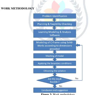
VI. WORK METHODOLOGY
JETIR1511020 Journal of Emerging Technologies and Innovative Research (JETIR) www.jetir.org 116 VII. LITERATURE SURVEY
B.Parthiban, P.Eazhumali, P.Kalimuthu [1], they used CATIA software for design and modelling and structural analysis has been applied on C-frame of hydraulic press structure and cylinder by ANSYS. According to the design and analysis results the thickness of the plate is reduced in frame about 72 kgs.
D. Ravi [2], studied on c-frame structure by using software pro-engineering and analysis carried out on ANSYS. Analysis was done for power press by reducing its frame thickness, web thickness, and bed thickness. The result obtained from analysis package is within the limit.
Mohammad Israr, Amit Tiwari, AnshulGangele [4], are given different power press terminology and fundamental evaluation based on formula for different component of power press. For designing the power press need to calculate required cutting force for material need to cut.
Romeo CIOARĂ, Ioan DAN [5], they used FEA method. they identify that constructive solution which provides to the frame the best stress and strain state. Analysing the stress in the frames with the ribbed walls, and found that the increased resistance of ribbed walls causes a „migration‟ of tensions to the front pillars areas.
Santoshkumar S. Malipatil, Prof. Yogita N. Potdar, Prof. A. C. Mattikalli [6], they compared original design of H frame type hydraulic press with design and optimized by using software tool (ANSYS) under the same loading conditions, constraints, and intended design purpose. They came to results of 57.56% weight reduction & 57.55% cost reduction of the H-frame hydraulic press.
Rajdipsinh G. Vaghela et.al [7]conducted a study on design and analyze the C-frame of the pneumatic power press. Design parameters are evaluated by analytical as well as software simulation using Ansys software. It optimizes the stress value and provides an improved thickness of the frame, which by this means reducing the material required manufacturing it given the stress on the frame continuing below permissible limits.
VIII. ASSUMPTION CONSIDERED
Following are the assumptions had been made for frame structure. 1. The load is .consider as a perfectly vertical.
2. Frame material is homogeneous and isotropic.
3. The base is bolted to a solid foundation so all the deflections of the base plate are zero.
4. As he frame is having the symmetrical cross section area, one side is to be consider for the purpose of analysis.
IX. DESIGN PROCEDURE OF C-FRAME PRESS
The frame is the base machine element in press. It is designed by the following steps.
1. Function
The main function of the frame is to withstand the force developed by the RAM. Frame is used for mounting and housing the press accessories like ram, die block, motor, flywheel, gears etc.
2. Determination of forces
The capacity of the press determines the major forces acting on the frame structure.
3. Material Specifications
Specification of Material Designation: St 42 W.
Tensile strength: 420 to 540 MPa. Density: 7850 kgf/m3.
Young‟s Modulus: 2.1 x 10⁵ N/mm2. Poisons Ratio: 0.3.
JETIR1511020 Journal of Emerging Technologies and Innovative Research (JETIR) www.jetir.org 117
Stress Concentration Factor: 1.25
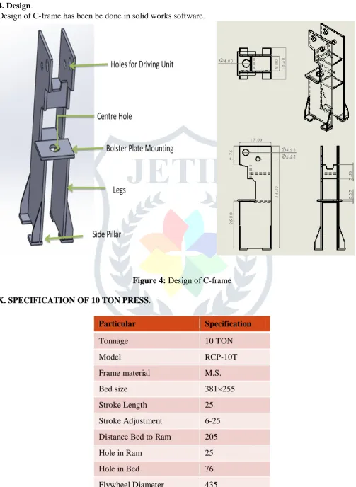
4. Design.
Design of C-frame has been be done in solid works software.
Figure 4: Design of C-frame
X. SPECIFICATION OF 10 TON PRESS.
Particular Specification
Tonnage 10 TON
Model RCP-10T
Frame material M.S.
Bed size 381×255
Stroke Length 25
Stroke Adjustment 6-25
Distance Bed to Ram 205
Hole in Ram 25
Hole in Bed 76
JETIR1511020 Journal of Emerging Technologies and Innovative Research (JETIR) www.jetir.org 118
Stroke Per Minute 75
Motor H.P. Required 1
Number strokes per minutes 75
Length × Width × Height 1100×1070×1525
XI. CONCLUSION
By this work we concluded that machine always works under impact load condition cause that continuous impact load and frame always experiences continuous tensile stress. Press deal with stresses because of that frequently structural failure problem occurs in machine. So we provide fillet instead of sharp corner in a plate which is useful to reduce failure in structure. And we also know that Fillet radius depends on load condition which directly experienced by frame and it can be found by using FEA tools.
We know that the parameters of design calculations of C-Frame playing important role in press design. So the selection of good parameters for design provides strength to the system. We also know that there are vast a scope of quality improvement and cost optimization of mechanical power press. It requires software based static analysis with main aim to optimize design of frame and to reduce material waste within C-frame assembly which directly leads to cost saving.
XII. REFERENCES
[1] B.Parthiban, P.Eazhumali, S.Karthi, P.Kalimuthu, “DESIGN AND ANALYSIS OF C TYPE
HYDRAULIC PRESS STRUCTURE AND CYLINDER”, International Journal of Research in Aeronautical and Mechanical Engineering, March 2014.
[2] D. Ravi, “COMPUTER AIDED DESIGN AND ANALYSIS OF POWER PRESS”, Middle-East
Journal of Scientific Research 20 (10): 1239-1246, 2014.
[3] H. N. Chauhan, M. P. Bambhania, “DESIGN & ANALYSIS OF FRAME OF 63 TON POWER
PRESS MACHINE BY USING FINITE ELEMENT METHOD”, Indian Journal of Applied Research July 2013.
[4] Mohammad Israr, Amit Tiwari, AnshulGangele, “DESIGN & OPTIMIZATION OF POWER PRESS
MACHINE”, International Journal of Engineering & Technology Innovations, Vol. 2 Issue 1, January 2015.
[5] Romeo CIOARĂ, Ioan DAN, “INCREASED RIGIDITY SOLUTIONS FOR C-FRAME
MECHANICALPRESSES”, Proceedings in Manufacturing Systems, Volume 6, Issue 2, 2011.
[6] Santoshkumar S. Malipatil, Prof. Yogita N. Potdar, Prof. A. C. Mattikalli, ” ANALYSIS AND
STRUCTURAL OPTIMIZATION OF 5 TON H-FRAME HYDRAULIC PRESS”, International Journal of Innovative Science, Engineering & Technology, Vol. 1 Issue 5, July 2014.
[7] Rajdipsinh G Vaghela, Ravi C Patel, Kanaksinh Gohil, “A REVIEW ON DESIGN & ANALYSIS OF
C-FRAME OF PNEUMATIC POWER PRESS USING FEA”, International Journal for Scientific Research & Development| Vol. 1, Issue 11, 2014.
[8] Romeo CIOARĂ, Ioan DAN, “PRE-TENSIONED C-FRAME FOR THE CRANK MECHANICAL
PRESS, STUDY OF THE STRESS AND STRAIN STATE”, Proceedings in Manufacturing Systems, Volume 7, Issue 4, 2012.
[9] “MECHANICAL PRESS TYPES AND NOMENCLATURE” by David Alkire Smith, Rev August 19,
2005.
[10] Hajra Choudhury S.K &HajraChoudhury A.K. Workshop Technology Vol. 2, Media Promoters&
Publishers Pvt. Ltd., Delhi, 1994.