IJIRT 145297
INTERNATIONAL JO URNAL OF INNOVATIVE RESEARCH IN TECHNOLOGY373
Design & Manufacturing of an Effective Steering System
for a Formula Student Car
Nikhil N. Gitay
1, Siddharth A. Joshi
2, Ajit A. Dumbre
3, Devesh C. Juvekar
41,2,3,4
Student, Department of Mechanical Engineering R.M.D.S.S.O.E., Pune
Abstract- S teering system is used to direct the vehicle in the desired path. While maneuvering, the vehicle should steer in response to the driver’s input command. The goal of this project is to design a good responsive steering system for high as well as low speed cornering for formula student car and retain the moderate cost,
manufacturability, and low weight. The main
consideration in design of the steering system is to produce pure rolling motion of the wheels while maneuvering the tightest corners. A safe design should be developed to ensure proper response to high speed cornering and heavy braking. It is essential to take human comfort and safety into consideration while designing. A steering system of lower steering ratio and weight as low as possible is designed, analysed and fabricated.
Index Terms- Turning radius, ergonomic, maneuver, ackerman, steering ratio
I. INTRODUCTION
The directional behavior of vehicle depends on the design of steering system. It is necessary to design a responsive steering mechanism which helps the driver in obtaining complete control on the maneuvering of the vehicle. Since the steering system is directly operated by the driver it is essential to take human comfort into consideration while designing the steering. The goal is to produce an optimal design to achieve higher strength to weight ratio . The purpose of the steering system is to direct the vehicle in the desired path. A purely mechanical rack and pinion mechanism is used for the vehicle. Steering ratio can be altered using different gear ratios for rack and pinion. An effective steering system should enhance the handling characteristics of the vehicle. A lower steering ratio is required for continuously changing the course throughout the race track. Steering effort and turning radius should lesser to
easily maneuver the vehicle along the tightest corner of the track.
II. DESIGN
A. Design Considerations
The first step in designing the steering system is to determine the Wheelbase and Track Width of the vehicle. In accordance with formula student competition rules a minimum of 60 inches of wheelbase is required.
Front track width should be greater than rear track width to ensure that while close
to any obstacle or vehicle, the rear inner safely passes without dashing.
The main aim is to obtain the turning radius as less as possible for maneuvering along a critical corner.
For a steering system, selection of geometry is a major factor. Implementing proper geometry according to the cornering conditions is required. Considering the ease and cost of manufacturing,
type of gear-pair and material is selected for rack and pinion.
B. Geometry Setup
There three types of steering geometries – Ackerman, Pro-Ackerman and Parallel steering. Parallel steering is not considered as an option as it causes the vehicle to understeer at a greater extent. As the formula student competitions require considerably lower speed cornering in dynamic events, for this purpose Ackerman Geometry is chosen. In Pro-Ackerman geometry, outer wheel steer angle being greater than inner wheel steer angle, the inner wheel gets dragged while cornering at lower speed and increase the steering effort.
IJIRT 145297
INTERNATIONAL JO URNAL OF INNOVATIVE RESEARCH IN TECHNOLOGY374
parameters like minimum wheelbase, track width andother chassis parameters regarding the steering system a basic Ackerman geometry was obtained. In this we performed numerous iterations until we get the desired result.
In the geometry the rack was displaced to its maximum possible position as it would in an actual vehicle. At this displacement of rack the steering angle and turning radius of the vehicle was obtained through the geometry. After performing several iterations by analyzing the effects of varying the steering parameters such as length of tie-rod, rack, steering arm etc. a desired result was obtained providing the turning radius least of all the iterations and all following the Ackerman rule.
The final steering geometry is as follows:
Fig. Ackerman Geometry
C. Geometry Validation
From the geometry,
Inner wheel steer angle (Ø) = 520 Outer wheel steer angle (ϴ) = 32.20 Wheelbase (L) = 1565mm
Front Track Width (B) = 1325mm Ackerman Condition,
Cot(ϴ) - Cot(Ø) = L/B
By calculating, the Actual Ackerman condition obtained varies by around 5% from the Ideal Ackerman condition which is to be achieved. Hence the system is almost accurate.
D. Steering Specifications
Table No.1
E. Design of Rack and Pinion
Rack and pinion linkage was used for its ease of construction, manufacturability and better strength.
1) Gear Selection
For rack and pinion spur gear was chosen for its ease in designing and lesser manufacturing cost.
According to the BIS (Bureau of Indian Standard), 200
Full Depth Involute gear profile was selected because of following advantages:
Lesser risk of undercutting and interference Better load carrying capacity
Better contact patch
2) Material Selection
Materials used in steering system should be lighter in weight and precise in operation. Also cost, manufacturability and reliability are important factors in material selection.
Light weight design and precise manufacturing are the main goals. If the manufacturing is not precise it can lead to ineffective steering mechanism.
From light weight point of view EN24, EN8, EN9 were not even considered. Light weight materials which can withstand the cornering and dynamic forces are Titanium, Carbon Fiber and Aluminium. Considering the cost and manufacturability Aluminium Alloy 7075-T6 was used.
Property Value
Density 2810 Kg/m3
BHN 150
Ultimate tensile strength (Sut) 541 MPa
Parameters Values
Steering Ratio 2:1 Front Track Width 1325mm
Rear Track Width 1193mm
Rack Length 530mm
Rack Travel 70.972mm
Tie-Rods 307.7mm
Steering Arm 64mm
Steering Arm Angle 21° Inner Steer Angle 52.01° Outer Steer Angle 32.29°
Wheelbase 1565mm
IJIRT 145297
INTERNATIONAL JO URNAL OF INNOVATIVE RESEARCH IN TECHNOLOGY375
Yield strength (Syt) 503 MPaModulus of elasticity (E) 71.7 GPa
Poisson's ratio 0.33 Melting point temperature 477 0
3) Design of Gear-Pair Design of Rack:
Number of teeth required for both side displacement of rack are 12.
To avoid clashing of teeth of pinion on the non -toothed part of the rack adding extra 5 teeth the rack. Hence,
No. of teeth on rack are 22. Design of Pinion:
Rack deflection wheel is turned through 520 = 35.486mm (Each side)
Consider, m = 2mm zI = d/m = πd/πm
πd (circumference of pinion) = rack travel zI = 35.486/2πzI = 5.647
Considering, steering ratio as 2:1 i.e. when steering wheel is turned by 104o wheel will turn by 52o For 104o of periphery of pinion no of teeth on pinion are 5.647 (6).
Teeth required for total rack travel are 12.
But the minimum number of teeth on a gear to avoid interference are 17.
Hence, Z = 17 mm
4) Beam Strength
When two gears are in mesh, the teeth of the gears act as a cantilever beam and a tangential load acts at the contact point of the two teeth. Beam strength is the tangential load capacity of the gear tooth.
Beam Strength, Fb = m.b.Y.6t b = 10m = 20 mm Y – Lewis form factor For 20o full depth profile, Y = 0.484 – 2.865/z Y = 0.3332
6t = Sut/3 = 176.67 MPa Fb = 10m2 x 176.67 x 0.3332 Fb = 588.66m2 N
5) Wear Strength
Along with bending strength a gear tooth should be durable enough against pitting, crowing and wearing
of the teeth. Wear Strength determines the capacity of the gear tooth against tooth fatigue and tooth surface wear.
Fw = b.Q.dp.K
Q- Ratio factor = (2Zg) / (Zg + Zp) K- Hardness factor = 0.45(BHN/100)2 Fw = 236.67m2 N
6) Forces and Moments in Steering system
Forces and moments were calculated arising due to normal reaction at tire-road interface due to vertical load and aligning torque while steering the vehicle. The driver must apply an effort on the steering wheel to overcome the aligning torque.
From suspension geometry following parameters where finalized which has a direct effect on steering response:
Fig. KPI
1. King pin inclination (λ) = 80 2. Scrub radius (d) = 55mm 3. Caster Angle (ν) = 50 4. Steer Angle (δ) = 520
Mass of the vehicle with driver – 250kg
Considering the weight distribution of the vehicle 40:60.
IJIRT 145297
INTERNATIONAL JO URNAL OF INNOVATIVE RESEARCH IN TECHNOLOGY376
Moment arising due to vertical load acting on theFront Wheels-
Fig. Moment due king pin inclination
MV = (FZR + FZL). d.Sinλ.Sinδ FZ – Vertical Load, N
Calculating the values of FZR and FZL considering the lateral load transfer while cornering. MV = 5917 N-mm
Moment arising due to castor angle-
Fig. Moment due to caster angle MV = (FZL - FZR). d.Sinν.Cosδ
MV = 1412 N-mm
Total Vertical Moment, MVT = 7329 N
Aligning Torque-
MAT = (MVL + MVR). cos√(52+82) MAT = 14459.7 N-mm
Total effective moment, M = 21788.75 N-mm
Tangential force across the pinion, M = FT . Steering Arm Length FT = 340.49 N
Peff = Ka. Km. Pt / Kv
Pt – tangential force on pinion From design data book, Km = 1.3
Kv = 1 Ka = 1
Peff = 443.63 N
7) Estimation of Module
Gear pair is weaker in wear strength than in beam strength.
Fw = FOS x Peff Consider, FOS-1.5 236.67m2 = 1.5 x 443.63 m = 1.68
Hence considering standard module, m= 2mm
After the estimation of module, the other dimensions of gear pair are determined.
Pinion Dimensions: Module of Pinion = 2mm No. of teeth on pinion = 17 Pitch circle diameter = 34 mm Width = 10 x m = 10 x 2 = 20 mm Addendum = 1 x m = 2mm Dedendum = 1.25 x m = 2.5 mm
Addendum circle = PCD + addendum = 38 mm Dedendum circle = PCD – dedendum = 29 mm
Rack Dimensions: Module = 2
No. of teeth on rack = 22 Diameter = 20 mm Length = 530 mm
F. CAD Model of Rack and Pinion
As per the obtained dimensions, the rack and pinion were precisely designed on the CATIA software for manufacturing.
CAD model of Pinion:
IJIRT 145297
INTERNATIONAL JO URNAL OF INNOVATIVE RESEARCH IN TECHNOLOGY377
CAD Model of Rack:Fig. CAD Model of Rack
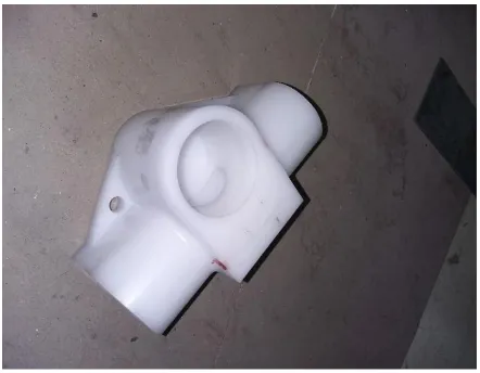
CAD Model of Casing:
Delrin Polymer material was used for the casing of rack and pinion. Delrin is very light in weight, cheap and easy to machine. It hard enough to withstand the forces.
Fig. CAD Model of Casing
CAD Model of Assembly:
Fig. CAD Model of Rack & Pinion assembly
F. FEA of the system using ANSYS
For FEA of the system the rack and pinion assembly of the system was put under motion constraints and tangential load was applied to check for the tooth failure and bending of the rack.
Using the results obtained from the FEA, minor changes were made in CAD model.
FEA of Rack and Pinion:
Fig. Equivalent Stress
Fig. Total Deformation Parameter Result
Stress 365Mpa
Deformation 0.9mm
FOS 1.38
G. Manufacured Parts
Rack and Pinion was manufactured at a very cheaper using a Milling machine. Assembly casing was manufactured on a DRO machine.
IJIRT 145297
INTERNATIONAL JO URNAL OF INNOVATIVE RESEARCH IN TECHNOLOGY378
Fig. Polymer CasingH. Steering effort calculation: Tangential force on pinion = 443 N Radius of pinion = 17mm
Torque on pinion = 7531 N-mm Radius of steering wheel = 125mm Force on steering wheel = 60.2 N
Thus, effort on Steering wheel is only 60.2N by one hand, which is within ergonomic consideration.
III. CONCLUSION
While designing any sub-assembly for the formula student vehicle, strength to weight ratio should always be maintained.
For rack and pinion, the casing should be precisely manufactured to exact center distance. Error microns can also affect the effectiveness of steering.
Steering effort should be adequate for the driver to easily maneuver through the corner.
REFERENCES
[1] Arvind Prasanth, "Design and Optimization of steering of formula SAE car using Solid works and Lotus Shark", Proceedings of World Congress on Engineering, Volume 2, July 2016. [2] Thomas D. Gillespie, “Fundamentals of Vehicle
Dynamics”, SAE Inc.
[3] Caroll Smith, “Tune to Win”, Aero Publishers Inc., USA, 1978.