Abstract— Through this paper we mention a new cogent method for 3D fitting ellipsoid and conic from scattered data, damaged by noise and outliers. This 3D statistical approach fitting builds on 3D Zernike moments. We prefer to estimate the probability density function p.d.f with the Zernike moment theory overseen by maximum entropy principle MEP. The purposed algorithm was successfully used in simulated noisy 3D conic forms images and 3D fitting a tumor for magnetic resonance imaging MRI. A deeper analysis of 3D fitting process is demonstrated to show its rapidness as well as its superior performance related noise immunity .
Index Term— Ellipsoid fitting, 3D conic fitting, MEP, p.d.f, Invariant Zernike moments, MRI, Noise immunity.
I. INT RODUCT ION
RECOGNITION or reconstruction of objects and patterns are an unduly important difficulty in computer vision [1], medical imaging [2], remote sensing, and in many other application areas. Finding a set of invariant descriptors is a key step to tackle this problem. In many applications[3], there is a demand to recognize 3D objects directly rather than from their 2D projections. Since modern technologies like computer tomography, magnetic resonance imaging MRI, and active range finders provide 3D data, the derivation of the invariants in higher dimensions than two has become very important. Invariants to imaging geometry have attracted the researchers’ attention for many years.
In this paper we were interested in imagery MRI in the frame notably of the monitoring of the patients presenting a tumour in an organ. MRI is scheduled at the level of main or supplementary exams in the diagnostic step of a lot of diseases. It also acts as a key role in the monitoring of the state of the patient and the quantification of an answer to a catch of medicines. So we introduce a 3D content based retrieval method founded on 3D Zernike moments. These moments are calculated as a projection of the function defining the object onto a set of orthogonal functions within the unit ball – the 3D Zernike polynomials given by Canterakis [4]. From these Canterakis has deduced affine invariant features of 3D objects
represented by a volumetric function. The modified Zernike moments are employed an approach whereas fitting 3D forms from scattered data.
This method is based on the expansion of a multivariate probability density function p.d.f. in terms of Zernike polynomials by means of Zernike moment [5], [6]. For this aim, the p.d.f. is approximated by a truncated series of polynomials. As the finding of the expansion order is a hard problem, we propose to approximate the p.d.f. for different orders and to select the optimal only now the single for which the entropy attains a maximum according to the Maximum Entropy Principal MEP. Having the optimum p.d.f, the extraction mode becomes a direct stage where the ellipse is constituted by the maxima of the p.d.f, while the points far from the curve (outliers) will present a low probability density value [7],[8],[9]. The 3D fitting problem is solved by a simply [10] and robust [11] approach combined our 2D fitting method [12] to superimposed cuts of MRI.
The outline of the rest of the paper is as follows: in the next section we acquaint a general theoretical framework for the computation of rotationally invariant descriptors and delineate the 3D Zernike descriptors in this framework. We also examine the 3D Zernike descriptors for accordance with the above criteria and 3D shape retrieval performance.
In Section 3, a formulation of 3D fitting problem is presented. Experimental results of our proposed reconstruction 3D technique, for medical imagery MRI and monitoring of volu me tumor, are presented in Section 4. Finally, section 5 deals with the summary of significant results and conclusion.
II. 3DZERNIKE MOMENT S AND DESCRIPT ORS
This section provides a systematic reconstruction of 3D Zernike moments and descriptors. We aim to give a framework providing a general method to handle this issue. We also recall the pertinent results of Canterakis [4] and describe our enhancement.
A. Moments
Moments in the case of pattern analysis are defined as projections of the object function f L2onto a set of functions
i , i
over the domain :.
Robust and Fast Ellipsoid Fitting from Noisy
Image: Computer solution for fitting
Tumours on MRI Scanner
dx x x f
f i
i ,i ( ) ( )
The behaviors and properties of a particular moment based representation are therefore defined by the set of function
.The collection of functions
is orthonormal, ifij j
i
, , where
i,
j
and
ij is the Kroneckerdelta.
B. Selection of basis functions
To sum up, we are looking for sets of functions forming complete orthogonal systems and allowing for construction of moments that are invariant [13] under rotation transformations. We derive the 3D Zernike moments [4]. The 3D Zernike
functions Znlm are defined as:
) , ( . ) ( )
( Rnl r Ylm
m nl
Z x
(1)
With constraints of l : l ≤ n and (n−l) be an even number.
Where we choose an angular function set ( )
(,)
m
l S or l S
and radial function m(r)
nl R .
Note that in general a particular function R reduces the dependence for 3D Zernike moments to l, and no dependency at all for 2D Zernike moments.
In 2D we can write the angular function as eil l
S ( ) which
is essentially the familiar Fourier basis function.
Spherical harmonics Ylmare given by:
m eim
l P m l N m l
Y ( , ) (cos ) ; where m
l N is a
normalization factor )! ( )! ( 4 1 2 m l m l l m l N
and
m l
P denotes
the associated Legendre functions. The above equation Eq.(1) can be written in Cartesian coordinates using the
harmonic polynomials m l e :
2 ( )
0 )
(x qkl x elm x
k m
nl
Z
(2)
x is expressed on spherical coordinates by:
xr(sinsin,sincos,cos)T
) , ( . )
( m
l Y l r m l
e x , where 2k = n−l and the coefficients
kl
q are determined to ensure the orthonormality of the
functions within the unit sphere:
k l k k l k k k k k l k k kl q 2 1 ) ( 2 . ) 1 ( 2 3 3 4 2 2 21 (3)
The orthonormality relation reads as follows:
m m l l n n d m l n Z m nl
Z
1 ( ). ( ) . .4
3
x x x x
m m l l n n dr d d r m l n Z m nl Z
. . sin ) ( ) ( 2 1 0 2π 0 π 0.
.
4
3
x x (4)We define the 3D Zernike moments Ωmnl of an object by f as:
1
(
)
(
)
Ω
4
3
x
f
x
Z
x
d
x
m nl m
nl (5)
Reconstruction. Since the functions Zmnl form a complete
orthonormal system, we can estimate the original function f by
a finite number of 3D Zernike moments
Ω
mnl :
n)
(
.
)
(
ˆ
l m m nl m nlZ
f
x
Ω
x
(6)Here, we sum over n[0,N],l[0,n] such that (n−l) be an even number and m [−l, l]. We consider the reconstruction to verify how much of the original object information is included in a set of 3D Zernike moments up to a given order n = N.
C.Computation of 3D Zernik e descriptors
In the First computational details , we expand Zmnl of Eq.(2) :
m l z u m y x m l m l l m
u u iu
m u m kl k q m m l c m nl Z ) ( 2 . ) ( 2 . ) ( 2 . 0 . 2 / ) (
0 ( 1) 2 2 .
m l t and u m s u r ) ( 2 2 , ) ( 2 and setting:
0 2 / ) ( 0 2 0 0 0 0 . 2 ) 1 ( . ) 1 ( . . 2 m l m u u u m kl k m m l rst nlm m l l i u m q c (8) m nlZ (x) : can be rewritten in a more compact form as a linear
combination of monomials of order up to n.
n t s r t z s y r x rst nlm m nlZ
(
x)
. (9)Finally, observing that using Eq.(9), the 3D Zernike moments m
nl
Ω of an object can be rewritten as a linear combination of
geometrical moments of order up to n:
n t s r t s r rst nlm x mnl
f
x
x
y
z
d
x
Ω
(
)
.
4
3
1 (10)
m nl
Ω
can be then rewritten as :
n t s r rst nlm m nl d t z s y r xf
x xx
Ω
1
(
).
.
4
3
(11)
Were Mrst denotes the geometrical moment of the object scaled to fit in the unit ball:
x
x
x
f
x
y
z
d
M
rst
r s t
1
(
).
(12)where x R3 refers to the vector x= (x, y, z)t. An important fact entailed by Eq.(11) is that in order to compute the 3D Zernike functions we only have to calculate the geometrical moments rather than valuing the complex exponential and associated Legendre function of spherical harmonics.
The explicit form is written as:
dz
dxdy
y
x
z
y
x
f
z
t r srst nlm m nl n t s r
)
,
,
(
.
4
3
Ω
(13)Then, 3D Zernike moments can be expressed with a two -dimensional moment nl in the plane z = const, parallel to xy
plane[10],[14] as shown in Fig. 1.
Fig. 1. Intersection with ellipsoid and a parallel plane
The intersection of a plane parallel to xy with a ellipsoid is a ellipse.
III. PROBLEM FORMULAT ION OF 3D FIT T ING
Our proposed approach is based on a decomposition of the 3D fitting problem on the 2D fitting task. Capable of showing a particularly good performance en terms of stability and robustness [12].We use the decomposition of a multivariate probability density function p.d.f in terms of Zernike polynomials by means of Zernike moment [6]. For this intention, the p.d.f is estimated by a truncated series of polynomials. Whereas computing the expansion order is a difficult problem, we propose to estimate the p .d.f for different orders and to select the optimal one as the one for which the entropy reaches a highest according to the Maximum Entropy Principal MEP [7], [8],[9].
From the optimal p.d.f, the detection mode becomes a direct task where the true points of the ellipse are the maxima of the p.d.f, while the aberrant points from the curve (outliers) will present a low probability density value. Selective collection of the maxima of the p.d.f is carried out using a proposed algorithm. An other task ellipse fitting gives the complete 3D primitives’ form.
A. Optimal Order Moments Selection using MEP
The finding of an expanding order is a hard problem and computationally expansive, because we ignore the order which gives a good quality of the estimated input image function. For this reason, we introduce the maximum entropy principle MEP for the search of this optimal order. This automatic technique
Intersection with ellipsoid
can estimate the optimal number of moments directly from the available data and does not require any a priori image information especially for noisy images.
Let be a set of estimated underlying probability density function for various Zernike moment orders
:}
...
1
/
{
p
G
w(14)
By applying the maximum entropy principle for noisy images, we deduce that among these estimates of the probability density function, there is unrivaled one probability
density function denoted
p
(
x
i,
y
j)
whose entropy is
maximum [7],[8], and which represents the optimal probability density function, and so gives the optimal moments orders’.
The Shannon entropy of
p
(
xi,
yj)
is defined as:.
j y i
x i j i j
y
x
p
y
x
p
p
S
,
))
,
(
log(
)
,
(
)
(
(15)and the optimal
p is such that :
S(p )MAX{S(p ) / p GW}
(16)
The approach to determinate the optimum order lies in estimating the p.d.f for many orders and selecting the optimal one for which the entropy reaches maximum.
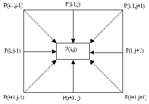
B. Ellipse Extraction Algorithm
We specify the ellipse as the local maxima of the estimated probability density function selected in the previous section. The practice consists in sliding a sweep mask of size 3x3 on the image. We compare the central pixel of the mask to its eight
neighbors in all directions as given in Fig.2,ensuring whether
or not this pixel belongs to ellipse.
Example to see the ability of the proposed ellipse fitting approach to noisy data [12]
We extend our 2D fitting approach [12], which illustrate the interesting features especially its noise performance, in 3D fitting general conic forms.
C. Ellipsoid Extraction Algorithm
Our algorithm is utilized for different noisy scattered data and is tried out for binary images corrupted by noise and outliers, where we considered the noise sensitivity in the case of Gaussian and impulsive noise.
Binary image with Noise:
The studies are done on a sampled ellipsoid Fig. 4. damaged with noise sigma =0.1 adding a rate of outliers equal to 2% from data points. The ellipsoid is fitted from extracted data points which corresponding to local maxima of estimated p.d.f. for an optimal order of Zernike moment Fig. 5.
Behaviour towards Outliers:
To see the readiness of the purposed ellipsoid fitting method to noisy data with added outliers, the proposed approach is tried out with a whole ellipsoids affected by a Gaussian noise with sigma=0.1 and rate of outliers equal 2% from data Fig. 6.
Fig. 2. T he central pixel P(i,j) with its eight close neighbors.
Rate= 2% Rate=10%
0 10 20 30 40 50 60 70 80 90 100 0
10 20 30 40 50 60 70 80 90 100
0 10 20 30 40 50 60 70 80 90 100 0
10 20 30 40 50 60 70 80 90 100
Fig. 3. Original and extracted ellipses by our approach [12], with noise (sigma=1 and a rate of outliers 2% ,10%)
0 10
20 30
40 50
0 10 20 30 40 50 -2 -1.5 -1 -0.5 0 0.5 1 1.5 2
D. General 3D conics forms
To draw out general 3D conics forms, we consider a whole 3D conic. The sampling conics affected by noise (sigma=0.1) and adding outliers (rate = 2 %) from data. The best 3D conic
points were deduced from the data points which corresponding to local maxima of approximated p.d.f on optimum order of Zernike moment. This is done for each ellipse of the 3D conic forms. Fitted 3D conic and original conic are depicted in Fig. 7 and Fig.8.
IV. EXPERIMENT AL RESULT S
A. 3D reconstruction technique for MRI
Before reconstruction, it is necessary to be sure first of all that cuts are definitely joined. For simplicity reasons, MRI provided in form of fine cuts Fig .9. but not jointed. This assures good quality pictures, but more hardly compatible for 3D reconstruction, since data are missing to reconstruct the volume.
We are extended our approach to fit 3D general conics, with any prior setting for fitting the ellipsoid or 3D general forms. To demonstrate the ability of the proposed 3D general forms, we use a data base with 24 images of skull Fig.10, where are
simulated a tumor, marking by points on each of cuts in which
0 10 20 30 40 50 0
20 40
0 50
0 50
0 200 400
0 10 20 30 40 50 0
20 40
0 10 20 30 40 500 20 40
0 50
0 50
0 200 400
0 10 20 30 40 500 20 40
0 10 20 30 40 500 20 40
0 50
0 50
0 200 400
0 10 20 30 40 500 20 40
0 10 20 30 40 500 20 40
0 50
0 50
0 200 400
0 10 20 30 40 500 20 40
0 10 20 30 40 500 20 40
0 50
0 50
0 200 400
0 10 20 30 40 500 20 40
0 20
40
0 20 40 -2 -1 0 1 2
0
50
0 20 40 -2 -1 0 1 2
Fig. 5. Fitting ellipsoid by our proposed approach fo r noise levels sigma=0.1 without outliers.
0 10 20 30 40 50
0 20 40
0 50 0 50
0 200 400
0 10 20 30 40 50
0 20 40
0 10 20 30 40 500
20 40
0 50 0 50
0 200 400
0 10 20 30 40 500
20 40
0 10 20 30 40 500
20 40
0 50 0 50
0 200 400
0 10 20 30 40 500
20 40
0 10 20 30 40 500
20 40
0 50 0 50
0 200 400
0 10 20 30 40 500
20 40
0 10 20 30 40 500
20 40
0 50 0 50
0 200 400
0 10 20 30 40 500
20 40
0 20
40
0 20 40 -2 -1 0 1 2
0 20
40
0 20 40 -2 -1 0 1 2
DEMARCHE D’AJUSTEMENT DE L’ELLIPSOIDE AVEC Outliers et Sigma=0.1
Fig. 6. Fitting ellipsoid by our proposed approach for noise levels sigma=0.1 and rate of outliers=2%.
0
10
20 30
40
50
0 10 20 30 40 50
-2 -1 0 1 2
it appears. The objectives are the 3D reconstruction tumor, the evaluation of its volume, the monitoring of the evolution of
tumor between two dates and visualization of the 3D fitted form of tumor inside the deflected organ itself rebuilds on 3D. The physician proceeds by marking of suspicions points in cut
given by a MRI scanner. A simulation of this stage is carried on Fig.11
We proceeded in the following by the reconstruction of the global volume of the tumor Fig.12,13
According to this demonstration of the applicability of our approach for the modeling of tumors by shapes 3D, we deduct
0 50
0 20 40
Ajustement d'une conique 3D,affectée par un bruit de sigma=0.1 et des Outliers
0 50 0 50
0 200 400
0 50
0 20 40
0 50
0 20 40
0 50
0 50
0 200 400
0 50
0 20 40
0 50
0 20 40
0 50
0 50
0 200 400
0 50
0 20 40
0 50
0 20 40
0 50
0 50
0 200 400
0 50
0 20 40
0 50
0 20 40
0 50
0 50
0 200 400
0 50
0 20 40 0
20
40 0
20 40 -2
0 2
0 50
0 50
-2 0 2
Fig. 8. Fitting 3D Conic by our proposed approach for noise levels sigma= 0.1 and rate of outliers = 2% .
0 10 20 30 40 50 0
10 20 30 40 50
0 200 400
0
10 20
30 40
50 0
10 20 30 40 50
0 200 400
0 10 20 30 40 50 0
10 20 30 40 50
0 200 400
0 5 10 15 20 25 30 35 40 45 50 0
5 10 15
20 25
30 35
40 45
50 0 100 200 300
that our method is valid, simple and characterized by the hardiness assured by our robust fitting [12].
B. 3D Extraction and visualization of two tumors
We can use our proposed approach to extract and visualize
two tumors marked in same image on time Fig..14,15,16,17.
Fig. 13. a. Elliptic Fitting from cuts b. 3D monitoring the Skull and the tumor
40 60 80
100 120 40 60 80 100 120
5 10 15 20 Le Volume de la Tumeur est egale :10.0524 mm3 à la date du :xx/5/2009 50
100 20 40 60 80 100 120
2 4 6 8 10 12 14 16 18 20 22 24 La position de la Tumeur dans le crane de Volume=10.0524 mm3 à la date du : xx/05/2009
Fig. 12. Extracted tumor by vertical Fitting elliptic models
20 40
60 80
100 0 20 40 60 80 100 120
2 4 6 8 10 12 14 16 18 20 22 24
Deux T umeurs Détectées et ajustées: Volume 1 = 19.45 mm3
Volume 2 = 9.78 mm3
Fig. 15. 3D visualization of two fitting tumors Fig. 16. 3D T wo fitting tumors localized First detected
tumor red color
Second detected tumor purple color
First detected tumor red color
Fig. 17. 3D Reconstruction tumor stage
V. CONCLUSION
In this paper we utilized the 3D Zernike descriptor for fitting general 3D primitive forms. The purpose of content based retrieval of 3D objects. We discussed some general rules for the construction of affine invariant object descriptors and derived the 3D Zernike descriptors within this framework. We furthermore considered the implementational issues: the severe instability of geometrical moments and hence the 3D Zernike descriptors optimal orders. We have proposed a novel approach to robust ellipsoid fitting, based on a statistical method using the 3D Zernike moment theory optimized by Maximum Entropy Principle MEP. This new concept of ellipsoid fitting is based on to four steps. In the first one, an intersection of a plane parallel to xy Fig.1, allowed to fit the 3D forms by applying our 2D robust proposed approach [12]. This allows it to be fast. In the second step, an estimation of the underlying probability density function p.d.f. using Zernike moment is carried out. In next s tep, the choice of the optimal p.d.f is performed using the maximum entropy principal criterion. Finally, the subset of local maxima pixels of the optimal p.d.f are extracted as the true points of each ellipse constituting the ellipsoid. The advantage of our algorithm is that no a priori information or intermediate steps about the original data image are needed. It demonstrates a great robustness against high noise levels and high rate of Outliers.
As it was shown in Section 4, the proposed method can be applied to fit of volumetric medical images for a MRI scanner. So, we developed a complete and automatic approach for imagery MRI, based on a new approach of fitting 3D by method of moments, allowing the 3D reconstruction of tumor and the evaluation of its volume. Our developed method offers also the monitoring of the evolution of tumor between two dates and visualization of the 3D fitted form of tumor inside the deflected organ, itself rebuilds on 3D.
Feasibility of the proposed 3D fitting method based on 3D Zernike moments and the simply technical used to reconstruct a 3D forms was demonstrated with a fitting and evaluation of tumor figures. We wish to apply our proposed approach for the 3D segmentation of medical imagery. Indeed, the method of fitting allows relaxing computers, both in terms of speed and memory requirement.We have for ultimate objective the real-time 3D allowing segmentation Interventional MRI or IMRI.
REFERENCES
[1] M.A. Bhuiyan, V. Ampornaramveth, S. Muto, and H.Ueno, "On T racking of Eye for Human-robot Interface", International Journal of Robotics and Automation, vol. 19,No. 1, pp. 42 -54, 2004.
[2] F. ROUSSEAU, F. Blanc, J. de Sèze, L.Rumbac, J. Armspach, "An a contratio appro- ach for outliers segmentation: application to multiple sclerosis in MRI", In: IEEE International Symposium on Biomedical Imaging: From Nano to Macro.(2008) 9_12
[3] J. PU, Bin Zheng, Joseph Ken Leader, and David Gur, "An
ellipse-fitting based method for efficient registration of breast masses on two mammographic views", Med Phys. February, 35(2): 487–494 2008
[4] N. Canterakis,"3D Zernike moments and Zernike affine invariants
for 3D image analysis and recognition", In 11th Scandinavian
Conf.on Image Analysis,1999.
[5] C.H. T he, R. T chin, "On image analysis by the methods of
moments", IEEE T rans. PAMI, Vol. 10, Jul. 1988, p. 496-513.
[6] S. X. Liao, M. Pawlak, "On image analysis by moments", IEEE T rans. PAMI, Vol. 18, no 3, p. 254 -266, Mar. 1996
[7] E.T . Jaynes, "On the rationale of maximum entropy methods",
Proceedings of the IEEE Vol. 70, no 9, sept. 1982.
[8] X. Zhuang, R.M. Haralick, Y. Zhao, "Maximum entropy image reconstruction", IEEE T rans. on signal processing. Vol. 39, no 6, p. 1478-1480, Jun 1991.
[9] H. Qjidaa and L. Radouane, "Robust line fitting in a noisy image by
the method of moments", IEEE Trans. Pattern. Anal. Machine
Intell., vol. 21, pp. 1216-1223, 1999.
[10] A. Jakliç, F. Solina "Moments of Superellipsoids and their Application to Range Image Registration", Special Issue on 3D
Image Analysis and Modeling ,IEEE SMC-PART B:
Cybernitics.2003
[11] K. Van Leemput, F. Maes, D. Vandermeulen, A. Colchester, and P. Suetens, "Automated segmentation of multiple sclerosis lesions by model outlier detection. ",IEEE Transactions on Medical Im aging, 20(8) :677–688, 2001.
[12] A. Cherkaoui, H. Qjidaa , S. Benzoubir, A. El Affar and K. Firdouss, "Robust Legendre Moments Ellipse Fit ting from Noisy Image", IJCSNS International Journal of Computer Science and Network Security, VOL.8 No.9, September 2008
[13] H. S. Kim, H. K. Lee, "Invariant image watermark using Zernike moments", IEEE T ransactions on CSVT , Vol.13, issue 8, pp.766 -775,Aug 2003