JETIR1704086 Journal of Emerging Technologies and Innovative Research (JETIR) www.jetir.org 385
PROGRESSIVE COLLAPSE ANALYSIS OF CABLE
STAYED BRIDGE CONSIDERING DIFFERENT CABLE
GEOMETRY
Jaydeep R. Rathod
1, Dipak K. Jivani
21P.G.Student, Department of Civil Engineering, DIET-Rajkot, Gujarat, India 2Assistant Professor ,Department of Civil Engineering, DIET-Rajkot, Gujarat, India
ABSTRACT: Bridges is the lifeline and important structure for any nation. Cable-stayed bridges are one of the most popular long-span bridge type due to its structural efficiency and pleasing aesthetics. Stays of cable-stayed bridges are critical structural elements which are subjected to corrosion, abrasion, wind, vehicle impact and malicious actions and these extreme loading scenarios may lead to severe damage and loss of cable which demands the progressive collapse analysis. Progressive collapse is a continuous spread and enlargement of initial local failure of structures, which is characterized by a disproportion between the initial failure and its resulting widespread collapse. Several bridge accidents occurred in recent years have demonstrated that the consequences of progressive collapse may be unpredictable and serious. It has been found that the ability to resist the collapse is determined not only by structural load-bearing capacity, but also by other structural attributes. Although great efforts have been contributed to the progressive collapse of building structures, comparably small attention have been paid in the same problem about bridge structures. In this research Xing jia bridge is consider with different geometry fan type , harp type & semi harp type cable system . Analysis of cable stayed bridge is done using computer programme SAP. Results obtained in form of Time period, Displacement and axial force are compared for different cable patterns. The results of the comprehensive evaluation of the cable failure show that the tread of the progressive failure of the cable-stayed bridges decreases when the location of the failed cables is closer to the pylon.
Keyword: - Cable stayed bridge, progressive collapse, cable loss, static analysis
I. INTRODUCTION
Cable-stayed bridges have become one of the most popular long-span bridge types due to its structural efficiency and pleasing aesthetics. A cable-stayed bridge consists of a bridge deck supported elastically by inclined cables, in one or two planes, which are attached at the far end to one or more main towers. It differs from the conventional suspension bridge system in that the cable-stayed system is self-anchored, with the cables stretching between the deck and tower points, thereby eliminating the need for external anchor blocks and utilizing inclined cables rather than the vertical hangers used in the suspension bridge system.
The bridges are generally designed based on the flexural strength of the girder, the compressive strength of the mast, and the tensile strength of the stay cables. By effective combination of the strength of each main member, cable-stayed bridges show excellent structural performance. Stay cables play the role of intermediate vertical supports for the superstructure instead of conventional piers or columns wall during earthquake in actual behaviour & building act as a Inverted Pendulum. As a result, the cable stayed bridges become quite suitable for long-span bridges.
According to the ASCE standard 7-02 (2002) progressive collapse is defined as “the spread of an initial local failure from element to element, eventually resulting in the collapse of an entire structure or a disproportionately large part of it.” The disproportionate failures are the small initial local failures caused by unforeseen events. These lead to the collapse of the entire structure, showing the inadequacy of the structure to offer resistance to the development of damage due to insufficient load carrying capacity. Bridges are primarily horizontally aligned structures with one main axis of extension. They are sensitive to dynamic excitation and offer less redundancy. Thus, the possible mechanisms of collapse are different compared to buildings. The reasons causing the unexpected events, such as collision with heavy bridge progressive collapse can be (i) vehicles, and earthquake, (ii) the degradation of structural performance due to corrosion and creep effect, and (iii) improper design or wrong construction methods.
II. NEED OF STUDY
A lot of collapses and performance failures have happens since the cable bridge inventions. Stays of cable-stayed bridges are critical structural elements which are subjected to corrosion, abrasion, wind, vehicle impact and malicious actions and these extreme loading scenarios may lead to severe damage and loss of cable . Such cable loss scenarios would lead to high impulsive dynamic loads in the structure that can potentially trigger a "zipper-type" progressive collapse of the entire bridge. Analysis of sudden loss of cables in cable stayed bridge is extremely critical and it has drawn the attention of researchers in recent years.
III. BEHAVIOUR OF CABLE STAYED BRIDGE
connection between the deck and the tower is also of great importance. This system primarily affects how effectively the structure carries live loads.
Figure 1 Structural behavior of cable stayed bridge
The longitudinal system is characterized by the ratio of the height of the towers to the central span, the relationship between the central span with the side spans, the connection of the deck to the approach viaduct, and the ratio of stiffness of the deck and the towers. The geometry of the tower depends on the type of suspension system (Fan, Semi-Fan, or Harp), the form of suspension at the deck (with center or side anchors), whether the deck rests directly on the tower, and the available space for anchoring and tensioning of the stays inside the tower.
IV. MODELLING OF BRIDGE
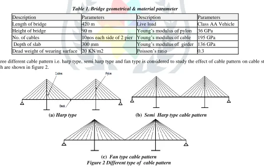
In this paper comparison of cable stayed bridge for different cable patterns for same span under dead load & live load in the form of vehicle load is carried out for static analysis. The analysis is carried out using widely used in SAP 2000. For study purpose The Xing Jia bridge considered which is 3-span composite cable-stayed bridge with an overall length of 420m (100m+ 220m+ 100m). The deck is 15.6 m wide. It comprises two longitudinal steel girders, approximately 2.5 m deep, transverse steel trusses at 3 m spacing and a reinforced concrete slab between 300 mm in depth. The deck of each cable-stayed cantilever section is supported by a total of 10 cables, with 10 cables arranged in each semi-fan configuration on each side of the pylon, in two planes, either side of the bridge deck. Each reinforced concrete pylon comprises two towers and two crossbeams, the lower one supporting the deck. The material and geometrical properties are mentioned in table 1.
Table 1. Bridge geometrical & material parameter
Three different cable pattern i.e. harp type, semi harp type and fan type is considered to study the effect of cable pattern on cable stayed bridge which are shown in figure 2.
(a) Harp type (b) Semi Harp type cable pattern
(c) Fan type cable pattern Figure 2 Different type of cable pattern
The cable tension is initially expected to have a significant effect on the bridge mechanical properties via geometric stiffness effects due to the cable tensions. The prior static analysis could begin with a neutral unloaded condition and impose a gravity load but this would result in initial bending stresses in the deck and low cable tensions. Instead, initial tensile strains estimated from the design tensions were set in the cables with the aim of producing neutral deck stresses and correct cable tensions. In fact it was necessary to iterate with different initial strains to generate close approximations to the design tension values in the cables for the optimization analysis. Bridge diagram with cable nos is shown in fig 3.
Description Parameters Description Parameters
Length of bridge 420 m Live load Class AA Vehicle
Height of bridge 90 m Young’s modulus of pylon 36 GPa
JETIR1704086 Journal of Emerging Technologies and Innovative Research (JETIR) www.jetir.org 387 Figure 3 Bridge diagram with cable nos
LOADING :
In accordance with the PTI recommendations for progressive collapse guidelines, the following loading combination is used when evaluating the progressive collapse:
Load = 1.0 D.C. + 1.0 DL + 0.75 LL + 1.0 PS + 1.0 CL Where , DL = Dead Load
LL = Live Load PS = Prestress of cables
CL = Equivalent force due to cable failure
Where DC = dead load of structural components, DW = dead load of wearing surfaces and utilities, LL = full vehicular live load placed in actual striped lanes , CL = impact force due to cable failure.
III. PROGRESSIVE COLLAPSE ANALYTICAL TECHNIQUES
Designing a bridge structure against progressive collapse has not been a major consideration. However, Cable stayed bridge is the only type of bridge structure routinely designed for cable loss. The loss of one or multiple no. of cables can lead to overloading and rupture of adjacent cables. Furthermore, the stiffening girder is in compression and a cable loss reduces its bracing against flexure. One or multiple cables are assumed to get damaged primarily to trigger the collapse progression and then the linear static analysis is performed.
In a linear static procedure, the bridge model is analyzed under its own self weight considering nonlinearity in the structural components. This analysis can be performed in two ways. After assuming the specific cables that are to be eliminated, firstly, the damaged cable(s) can be removed and the analysis is carried out on the remaining structure. Secondly, an equivalent and opposite yield force can be introduced to the damaged cables to nullify their contribution to the structure as shown in figure 4. The axial force carried by the eliminated cable gets redistributed to the supporting elements after its elimination from the structure. Stresses increase in those components and when they exceed the yield limit, that corresponding element also fails. So a collapse progression could be started .
Figure 4 Static analysis Load direction due to cable loss
IV. RESULTS AND DISCUSSION
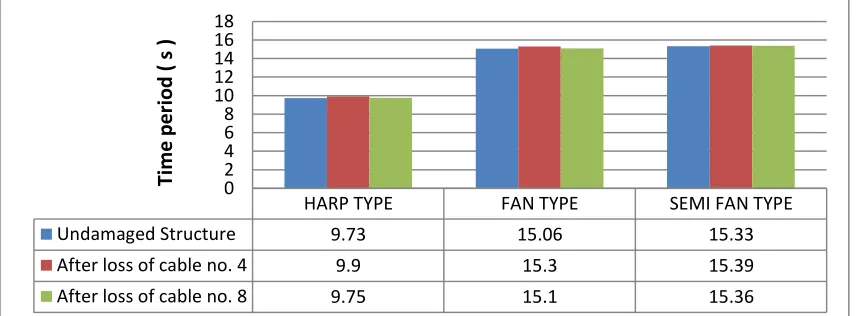
Time period is a property of system, when it allows to vibrate freely without any external force and it depends on mass and stiffness of the structure. Fundamental time period is inversely proportional to the frequency of the structure. With loss of cable away from the pylon time period is increase as compare to loss of cable near to the pylon. Among all cable patterns fan type cable pattern has higher increment in time period as compare to harp and semi harp cable systems. In Semi harp cable systems not much difference in time period after loss of different positioned cables . It indicates higher stability than other cable patterns. Results are shown in below figures.
Figure 5 Time-period comparison for all cable pattern after loss of different positioned cables
HARP TYPE FAN TYPE SEMI FAN TYPE
Undamaged Structure 9.73 15.06 15.33
After loss of cable no. 4 9.9 15.3 15.39
After loss of cable no. 8 9.75 15.1 15.36
0 2 4 6 8 10 12 14 16 18
Ti
me
p
e
ri
o
d
(
s
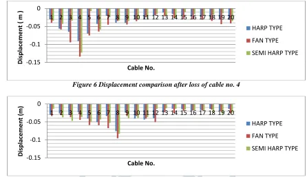
A thorough investigation is done on the cable stayed bridge model to study the path of failure progression in an accurate manner. The main structural model and models with different cable loss are analyzed to visualize the load distribution. Displacement comparison for different type of cable patterns for cable stayed bridge is shown below after loss of different positioned cables. Results show that displacement is higher when loss of cable away from the pylon as compared to loss of cable near to the pylon. Maximum displacement occur in fan type cable pattern.
Figure 6 Displacement comparison after loss of cable no. 4
Figure 7 Displacement comparison after loss of cable no. 8
Figure 8 Displacement in fan system after loss of cable no. 4
Figure 9 Displacement in semi harp system after loss of cable no. 4
Figure 10 Displacement in harp system after loss of cable no. 4
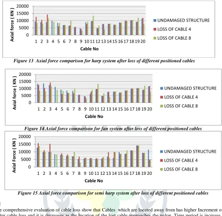
There can be two types of cable loss scenarios. If an end cable fails first, a huge amount of stress gets redistributed to the remaining structure resulting in a significant amount of increase in the axial forces in the remaining cables and stresses in the girders and the deck. Now this redistribution ratio also depends upon the position of the elements. The remaining end cables attract more axial force than the middle cables. These end cables were already carrying high axial tensions initially, so they are more vulnerable to damage as a slight increase in the axial force can trigger their failure. Therefore, their chance of failure is much greater than the others due to the load redistribution. Results are shown below.
-0.15 -0.1 -0.05 0
1 2 3 4 5 6 7 8 9 10 11 12 13 14 15 16 17 18 19 20
D
ispl
ace
m
en
t
(
m
)
Cable No.
HARP TYPE
FAN TYPE
SEMI HARP TYPE
-0.15 -0.1 -0.05 0
1 2 3 4 5 6 7 8 9 10 11 12 13 14 15 16 17 18 19 20
D
isp
lac
e
m
e
n
t
(m
)
Cable No.
HARP TYPE
FAN TYPE
JETIR1704086 Journal of Emerging Technologies and Innovative Research (JETIR) www.jetir.org 389 Figure 13 Axial force comparison for harp system after loss of different positioned cables
Figure 14 Axial force comparison for fan system after loss of different positioned cables
Figure 15 Axial force comparison for semi harp system after loss of different positioned cables
V. CONCLUSION
The results of the comprehensive evaluation of cable loss show that Cables which are located away from has higher Increment of axial forces in adjacent cable after cable loss and it is decreases as the location of the lost cable approaches the pylon. Time period is increase when loss of cable happens away from the pylon . Fan type pattern has more Time-period as compared to other cable pattern . the cables near the vicinity of the ruptured cable do not reach the tension yield and the maximum nodal vertical displacement decreases when the lost cables are near the pylon. Thus, the resistance to the progressive failure of the cable stayed bridges increases as the locations of lost cables near the pylon. Furthermore, the vertical displacements of the nodes at the other side of the pylon cannot be considered as negligible under the loss of outside cables. The vertical deflection at the other side of the pylon decreases as the location of the lost cable approaches the pylon.
VI. REFRENCES 0 5000 10000 15000 20000
1 2 3 4 5 6 7 8 9 10 11 12 13 14 15 16 17 18 19 20
A xi al for ce ( K N ) Cable No UNDAMAGED STRUCTURE
LOSS OF CABLE 4
LOSS OF CABLE 8
0 5000 10000 15000 20000
1 2 3 4 5 6 7 8 9 10 11 12 13 14 15 16 17 18 19 20
A xi al for ce ( K N ) Cable No UNDAMAGED STRUCTURE
LOSS OF CABLE 4
LOSS OF CABLE 8
0 5000 10000 15000 20000
1 2 3 4 5 6 7 8 9 10 11 12 13 14 15 16 17 18 19 20
A xi al Fo rc e ( K N ) Cable No UNDAMAGED STRUCTURE
LOSS OF CABLE 4
LOSS OF CABLE 8
[1] Agarwal, J., England, J., Blockley, D., 2006. Vulnerability analysis of structures. Structural Engineering International, 16(2):124-128.
[2] Wolff, M., Starossek, U., 2008. Robustness Assessment of a Cable-Stayed Bridge. Proceeding of the International Conference on Bridge Maintenance, Safety and Management, Seoul, Korea.
[3] Starossek, U., 2006. Progressive Collapse of Bridges— Aspects of Analysis and Design. Proceedings of the International Symposium on Sea-Crossing Long-Span Bridges, Mokpo, Korea.
[4] Starossek, U., 2007. Typology of progressive collapse. Engineering Structures, 29(9):2302-2307.
[5] Fu, F., 2010. 3-D nonlinear dynamic progressive collapse analysis of multi-storey steel composite frame buildings —Parametric study. Engineering Structures, 32(12): 3974-3980. [doi:10.1016/j.engstruct.2010.09.008]
[6] Gross, J. L., and McGuire, W. (1983). “Progressive collapse resistant design.” ASCE, Journal of Structural Engineering, 109(1). [7] PTI for progressive collapse