e-ISSN: 2278-067X, p-ISSN: 2278-800X, www.ijerd.com
Volume 10, Issue 2 (February 2014), PP.08-15
Design, Manufacturing and Testing of Circular Welding
Positioner
Prof. N.B.Totala, Sarang S. Bhutada, Nakul R. Katruwar,
Rachan R. Rai, Ketan N. Dhumke
1(Assistant Professor, Department of Mechanical Engineering, MIT Academy of Engineering, Alandi (D), Pune Maharashtra 412105.)
2,3,4&5 (Department of Mechanical Engineering, Sinhgad Institute of Technology, Pune Maharashtra 411041.)
Abstract:- This paper deals with the construction and working of all components required for welding positioner.With an increase in size and complexity of today‟s welding requirements, new techniques must be developed so as to ease the operator‟s burden and ensure uniform and efficient circular welding.In this paper the various components of the circular welding positioner are critically designed, manufactured and tested, along with which a cost and time parameters have been included to aid in the manufacturing of the positioner. The arc torch is fixed to an adjustable clamp, not hand held. It is different from a robot since operator‟s continuous surveillance and intervention are essential for successful work
Keywords:- Circular welding, CO2 welding, Welding positioner, Welding gun subassembly, Automation
I.
INTRODUCTION
Welding is a process for joining different materials. The large bulk of materials that are welded are metals and their alloys, although the term welding is also applied to the joining of other materials such as thermoplastics. In order to join two or more pieces of metal together by one of the welding processes, the most essential requirement is heat. Pressure may also be employed, but this is not, in many processes essential. The use of welding in today‟s technology is extensive. It had a phenomenal rise since about 1930, this growth has been faster than the general industrial growth. [1]
Welding-positioner is a special accessory tool or manipulator that helps achieving the required economic results of a welding program. It all depends on the process used, on what is going to be welded, on quantity and quality of what has to be provided, and on whether the Return on Investment (ROI) is going to justify the expense for procuring the tool.
Welding positioner is an advanced implement that helps perform welding. It keeps in place the elements being welded, while providing some relative, progressive, smooth movement between the torch of a fusion welding head and the joint to be welded. The movement is relative, because it does not matter if the arc source or the work is fixed, while the other element moves along simple lines. A welding table, although very useful, has no intrinsic movements available so that it falls short of the above definition. Welding-positioner is a necessary tool for highly productive mechanically assisted manual welding for those different processes that supply filler metal continuously from a spool (GMAW, SAW) or for GTAW with thin sections if filler metal is not required.
A set of uniformly placed good quality tack welds has to be made to bridge the gap and to provide some rigidity against the stresses developed during welding. A Welding-positioner assures enhanced quality and increased productivity. This is the most important gain, because of reduction of downtime, and also as the welding parameters can be selected to provide the maximum weld deposition rate, compatible with acceptable (not excessive) heat input. Arc-on time is equally increased resulting in potential reduction of welding costs.
Jun Yong Choi et al suggested that the application of fracture mechanics is being increased gradually to assess the safety of welding crack- containing structures and suggest cracks initiate and propagate in welding joint part due to impact and fatigue load, therefore it is necessary to improve welding performance and fracture resistance of welding part in structure. Their study presents a suitable CO2 welding process for lap joints, taking into consideration tensile strength and fatigue strength under various welding conditions. [3]
Lelio Della Pietra investigated experimentally the tension variation in a flat belt transmission which is obtained by measuring its deformation with electrical resistance strain gauges as transducers. He also proved that two models of validity showing the strength of weld are equally important which were one addition arc and sliding to presence of shear strain along different sliding angles on driving and driven pulleys. These model gave the force transmitted into the device. [4]
II.
DESIGN
METHODOLOGY
In our attempt to design a special purpose machine we have adopted a very careful approach, the total design work has been divided into two parts:
System design
Mechanical design
A. System Design
System design mainly concerns with the various physical constraints and ergonomics, space requirements, arrangement of various components on the main frame of machine, no. of controls, position of these controls, ease of maintenance, scope of further improvement, height of m/c from ground etc. In system design we mainly concentrate on the following parameters;
1. System selection based on physical constraints:-
While selecting any m/c it must be checked whether it is going to be used in large scale or small scale industry in our case it is to be used in small scale industry so space is a major constraint. The system is to be very compact. The mechanical design has direct norms with the system design hence the foremost job is to control the physical parameters.
2. Arrangement of various components:-
Keeping into view the space restriction, the components should be laid such that their easy removal or servicing is possible moreover every component should be easily seen and none should be hidden. Every possible space is utilized in component arrangement.
3. Components of system:-
As already stated, system should be compact enough so that it can be accommodated at a corner of a room. All the moving parts should be well closed and compact. A compact system gives a better look and structure.
4. Chances of failure:-
The losses incurred by owner in case of failure of a component are important criteria of design. Factor of safety while doing the mechanical design is kept high so that there are less chances of failure. Periodic maintenance is required to keep the m/c trouble free.
5. Servicing facility:-
The layout of components should be such that easy servicing is possible especially those components which required frequent servicing can be easily dismantled.
6. Height of m/c from ground:-
For ease and comfort of operator the height of m/c should be properly decided so that he may not get tired during operation also enough clearance should be provided from ground for cleaning purpose.
7. Weight of machine:-
B. Mechanical Design
In Mechanical design the components are categories in two parts.
Design parts
Parts to be purchased
For design parts detail design is done and dimensions thus obtained are compared to next higher dimension which are readily available in market. This simplifies the assembly as well as post production servicing work. The various tolerances on work pieces are specified in the manufacturing drawings. The process charts are prepared and passed on to the manufacturing stage.
The parts are to be purchased directly are specified and selected from standard catalogues and are specified so as to have case of procurement.
A. DESIGNOFPARTSMotor Selection
Thus selecting a motor of the following specifications 1. Single phase AC motor
2. Commutator motor 3. TEFC construction 4. Power = 1/15 HP = 60 watt 5. Speed= 0-6000 rpm (variable) Motor torque calculated T=0.095 Nm
B. Design Of Worm Shaft
Material selection: -Designation: EN 24 [2] ASME CODE FOR DESIGN OF SHAFT:
τ per = 0.18 x 800= 144 N/mm2 τ per = 0.30 x 680 =204 N/mm2
Considering minimum value of the above values, τ per = 144 N/mm2
Shaft is provided with key way, this will reduce its strength. Hence reducing above value of allowable stress by 25%.
τ per = 108 N/mm2
This is the allowable value of shear stress that can be induced in the shaft material for safe operation.
To calculate worm shaft torque:
Power = Motor is 60 watt power, run at 6000 rpm, connected to worm shaft by belt pulley arrangement with reduction ratio 1:5.
Hence input to worm gear box = 1200 rpm T=0.48Nm
C. Design Of Worm Wheel Shaft
Material Selection: - Designation: EN 24[5] Asme code for design of shaft:
τ per = 0.18 x 800 = 144 N/mm2 τ per = 0.30 x 680 =204 N/mm2
Considering minimum value of the above values, τ per = 144 N/mm
2
Shaft is provided with key way, this will reduce its strength. Hence reducing above value of allowable stress by 25%.
τ per = 108 N/mm2
This is the allowable value of shear stress that can be induced in the shaft material for safe operation.
D. Design Of Key
Selecting parallel key from standard data book for given application. Material of key is 55C8 [3]
Table I
For Shaft Diameter(mm) Above 12
Up to 17
Key cross section(mm) Width (b) 5
E. Design Of Worm And Worm Wheel
The pair of worm and worm wheel used in the machine is designated as
1/80/10/1.5.The worm is made of case hardened steel EN24 whereas the worm wheel is made of Phosphor bronze. [6]
As the drive is capable of transmitting 0.1796 kW and we intend to transmit 0.06 kW therefore the drive is safe.
F. Selection Of Bearing
1. Selection of worm shaft bearing:
Deep groove ball bearing is most frequently used bearing. These bearing take the loads in radial as well as axial. Here, calculated shaft diameter “d = 16 mm” which is safe under torsional load but during selection of ball bearing we found that 16 mm bore diameter bearing is not available in standard catalogue of bearing. So we select next standard size of shaft diameter “d = 17 mm” from bearing series 6003ZZ. [6]
Table II
Brg Basic Design No (SKF)
Bore dia.(d) mm Outside dia.(D) mm Width(B) mm Basic capacity Static „Co‟ (N)
Dynamic „C‟ (N)
6003ZZ 17 35 10 2850 4650
2. Selection of worm wheel shaft bearing
Deep groove ball bearing is most frequently used bearing. These bearing take the loads in radial as well as axial. Here, calculated shaft diameter “d = 22 mm” which is safe under torsional load but during selection of ball bearing we found that 22 mm bore dia. bearing is not available in standard catalogue of bearing. So we select next standard size of shaft diameter “d = 25 mm” from bearing series 6005ZZ. [6]
Table III
Brg Basic Design No (SKF) Bore dia.(d) mm Outside dia.(D) mm Width(B) mm Basic capacity Static „Co‟ (N)
Dynamic „C‟ (N)
6005ZZ 25 47 12 7800 5200
G. Design Of Open Belt Drive
Motor pulley diameter = 20 mm Reduction ratio = 5
Input shaft pulley diameter = 100 mm Coefficient of friction = 0.2
Maximum allowable tension in belt = 200 N Center distance = 120 mm
Arc of contact for smaller pulley (α) =141° [7] Ratio of belt tension=4.2[7]
Width at the base is given by (b2) =3.1mm Area of cross section of belt (A) = 18.2 Mass of belt per meter length = 0.23 kg/m Velocity = 4.19 m/sec
Centrifugal tension (Tc) = 4.034 N
Tension at tight side (T1) = 200 - 4.034=195.966N Tension on slack side (T2) =49N
H. Design Of Screw For Tilting Mechanism
Material selection: - [6]
Table IV
Material Bearing Pressure, (N/mm2) Rubbing Speed
Screw Nut
Steel C.I 13-17 Low Speed
Calculate load (w) on screw
W = Weight of work piece + Weight of base plate W = 315.1 N
Core diameter of screw (dc) = d – p = 8 – 1 = 7 mm z = no. of threads in engagement with nut = 12
I. Design Of Spring
Material selection: - [6]
Patented cold drawn steel wire (unalloyed). Sut=1390N/mm2
Permissible shear stress=0.3×Sut=417N/mm2
We assume maximum force that can be applied by hand (P) is 70 N. As there are two springs, therefore force on each spring is 35 N.
Assume spring index, C = 5 [6]
From required load condition the free length is 60mm.
Table V: Designed Table
Sr. No Part Name Dimension
1. Motor 60 W, 0-6000 rpm
2. Worm Shaft Ø = 16mm
3. Worm Wheel Shaft Ø = 22mm
4. Key 5×5×24mm
5. Bearing 6003ZZ,6005ZZ
6. Worm And Worm Wheel 1/80/10/1.5
7. Open Belt Drive FZ 6×500
8. Screw Ø = 8, 1 mm pitch
9. Spring d = 1.2 mm, Lf = 60mm
III.
MANUFACTURING
Details of manufacturing is given below
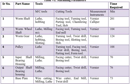
A. Machining Parameters[8,9,10]
Table VI: Machining Parameters
Sr No. Part Name Tools Time
Required
M/C tools Cutting Tools Measurement Instruments
Min
1 Worm Shaft Lathe, hobbing
Facing tool, Turning tool, Parting tool, Chamfering Tool, Hob
Vernier Calliper
201
2 Worm Wheel Shaft
Lathe, Milling m/c
Facing tool, Turning tool, End mill
Vernier 104
3 Worm Gear Lathe, hobbing, Slotting.
Turning tool, Twist drill, Boring tool, Slotting tool, Hob.
Vernier 124
4 Pulley Lathe Turning tool, Facing tool, Twist drill, Boring tool, Parting tool, Form tool.
Vernier 108
5 Input Shaft Bearing Housing
Milling, Lathe.
Facing cutter, Twist drill, Boring tool
Vernier 70
6 Output Shaft Bearing housing
Milling, Lathe.
Facing cutter, Twist drill, Boring tool.
Vernier 76
7 Base Plate Wire cutting, Milling, Lathe
Wire cutter, End Mill, Twist drill
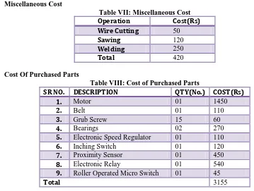
B. Miscellaneous Cost
Table VII: Miscellaneous Cost
Operation Cost(Rs)
Wire Cutting 50
Sawing 120
Welding 250
Total 420
C. Cost Of Purchased Parts
Table VIII: Cost of Purchased Parts
SR NO. DESCRIPTION QTY(No.) COST(Rs)
1. Motor 01 1450
2. Belt 01 110
3. Grub Screw 15 60
4. Bearings 02 270
5. Electronic Speed Regulator 01 110
6. Inching Switch 01 120
7. Proximity Sensor 01 450
8. Electronic Relay 01 540
9. Roller Operated Micro Switch 01 45
Total 3155
D. Total Cost
Total cost = Raw Material Cost + Machining Cost + Miscellaneous Cost + Cost of Purchased Parts + Overheads. Total cost = 4800 + 3560 + 420 + 3155+ 1500
Hence the Total Cost Machine = Rs.
13435/-IV.
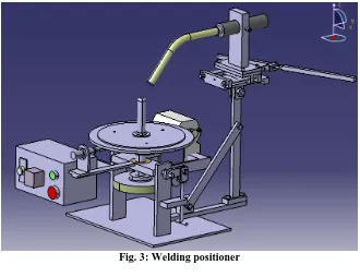
CAD REPRESENTATION:
Fig. 2: Subassembly of Gun Holder
Fig. 3: Welding positioner
V.
TESTING
For testing purpose following parameters are considered: [1] 1. Electrode Size
For work piece thickness of 2.0 - 4.0 mm, wire diameter 1.0 – 1.2 mm is selected. 2. Welding Current and Voltage
For electrode diameter 1.0 – 1.2 mm, current range is 60 – 160 A, voltage range is 16 – 25 V. 3. Arc Travel Speed
The speed at which arc moves along the joint is 0.44 m/min. 4. Results
Time required for loading and unloading the job = 15 sec Time required for actual welding process = 15 sec Total cycle time = 30 sec
VI.
DISCUSSIONS
The designed welding positioner can be used for the following applications. 1. To weld the bush inside fork of a bike.
2. CO2 welding of circular or staggered welded joints is possible. 3. Welding of pipe and flange can be done.
4. Pressure vessel heads, nozzles and other fittings can be welded.
5. Welding of small circular automobile components for example silencer.
VII.
FUTURE SCOPE
1. Currently the welding positioner is used with welding gun which is fed manually and has a spring return mechanism which can be replaced and automated with pneumatic cylinders.
2. The guide bars can be replaced with linear guide ways in order to increase accuracy. 3. The entire positioner can be controlled using Microprocessors to increase automation.
VIII.
CONCLUSION
1. A Heavy load capacity of table of about 30 kg is achieved. 2. Adjustable table speed (0 to 15 rpm).
3. Auto stop feature, operation at precise positions (starts and end process). 4. Multiple indexer positions (3), enables to make staggered welded joints.
5. Ease of operation, as table automatically stops as per indexer button position and next operation is started by merely pressing the inching switch.
6. Compact, the entire drive assembly fitted below the table itself, and the controls are placed on the front at ergonomic positions.
7. Weight and easy to operate. 8. Low power consumption (60 watt). 9. Precise and noiseless in operation.
10. Less skilled operator can perform operation.
REFERENCES
[1]. “Welding Technology”, O P Khanna; Dhanapat Rai Publication; 1999.
[2]. Jafar Takabi, M.M. Khonsari, “Experimental testing and thermal analysis of ball bearings”, Tribology International 60 (2013) 93–103.
[3]. Lelio Della Pietra et al “Tension in flat belt transmission: Experimental investigation”,Mechanism and Machine Theory 70 (2013) ,pp 129–156
[4]. Jun young choi et al., “Effect of current and Voltage on on strength of lap joint with CO2 welding process key engineering materials”, vol. 297-300(2005),pp 2859-2863
[5]. “P S G Design Data Book”; Published by Kalaikathir Achchagam, 2011.
[6]. “Design of Machine Elements”, V B Bhandari; Tata McGraw Hill Publication; 2009. [7]. “Machine Design”, R S Khurmi and J K Gupta; S Chand Publication; 2010.
[8]. “Engineering Mechanism”, Erdman and Sandor; Prentice Hall Publication; 2001. [9]. “Manufacturing Science”, Amitabh Ghosh and Malik; East West Publication; 2011.