e-ISSN: 2278-7461, p-ISSN: 2319-6491
Volume 8, Issue 1 [January 2019] PP: 92-101
Mitigation of Harmonics and Power Quality Improvement for
Grid-Connected Wind Energy System using Unified Power Flow
Controller Based on Spontaneous Energy Optimization
Algorithm
Dr.R.Sankarganesh, P. Ashok Kumar
B.Tech., M.E., Ph.D., Associate Professor, Department of Electrical and Electronics Engineering, Vinayaka Mission’s Kirupananda Variyar Engineering College, Vinayaka Mission’s Research Foundation (Deemed To
Be University), Salem-636308, Tamilnadu, India.
PG Scholar, M.E – Power System Engineering, Department of Electrical and Electronics Engineering, Vinayaka Mission’s Kirupananda Variyar Engineering College, Vinayaka Mission’s Research Foundation
(Deemed To Be University), Salem-636308, Tamilnadu, India. Corresponding Author: Dr.R.Sankarganesh
ABSTRACT:This model gives a new technique used to control a power flow of DC voltage regulation in the electric power transmission system; the method is Unified Power Flow Controller (UPFC). It is based on a hybrid technology which combines a Radial Basis Function (RBF) and also sliding mode technique of the system is more advantage of their general classification. Perturbation bounds are not needed in the proposed controller and the full state of the non linear system. Therefore, it is very productive, and its system parameter produces an optimal response in the face of uncertain and disturbances. The proposed controller performance is evaluated through numerical simulations on a different power system with a classical SEO controller. Further, Spontaneous Energy Optimization (SEO) Algorithm based UPFC controller is designed to improve transient performance. Simulation results reflect the robustness of the proposed Spontaneous Energy Optimization controller for better reactive power management to adjust the voltage stability in comparison with the conventional PI and fuzzy-PI controllers. In addition to this, system stability analysis is performed based on for supporting the robustness of the proposed controller. The Simulation results give the effectiveness, robustness, and superiority of the proposed controller.
KEYWORD: Unified Power Flow Controller (UPFC). PI controller. Radial Basis Function (RBF), Spontaneous Energy Optimization (SEO).
---Date of Submission: 26-05-2019 ---Date of acceptance:08-06-2019
---I.
INTRODUCTION
In a modern power system, advent and installation of extensive non-linear electronic devices, as well as the sudden disturbing events, causes various power quality (PQ) problems. These PQ problems include voltage sag, swell, harmonics, flicker, etc. and are responsible for distorting, the nature of supply voltage and the current waveform. Thus these PQ problems degrade the performance of sensitive loads like electric drives, computer systems, and industrial electronic controllers. It further impinges the economic loss to industrial customers.
Figure 1: Unified Power Flow Controller For Power Stability Improvement.
This presents a hybrid active power filter. There are a passive filter and an active power filter in the adopted system. The passive power filter is used to filter the low order harmonic current with a significant power rating. The active power filter with a low power rating is used to filter the other high order harmonics. Therefore the cost of the hybrid active power filter is much smaller than shunt active power filter. The neutral point diode clamped inverter is operated as an active power filter. A dc-link voltage controller and a phase locked loop circuit used in the system to generate the reference line currents. The hysteresis comparators are adapted to track current commands. Experimental results based on a laboratory prototype are provided to verify the effectiveness of the control scheme.
II.
LITERATURE REVIEW
The reliability of the power transfer capability is important in the power grid; the Unified Power Flow Controller (UPFC) is given to the power grid operation. And is based on the distance protection analyzed in the power transmission system. In this proposed system the distance protection zone effectively identifies the internal faults and obvious faults [1].
The UPFC capability is attenuating SSR in the integration of wind farm. The SSR is used to measure the controlling of the series converter while wide area signals as well as it's utilized in parallel for another oscillation damping It has the effective functionality in promoting the system operation security and the service reliability [2].
The most important energy efficiency issues is voltage sag is one of in the professional challenge of use. The voltage sags a voltage and capacity injection can compensate for the delivery system. By injecting voltage with a phase advance concerning the sustained source-side voltage, reactive power can be utilized to help voltage restoration. Hence, the consumption of real power, from the perspective of the energy supply device, can be reduced [3].
The dynamic voltage restorer (DVR) has become popular as a cost-effective solution for the protection of sensitive loads from voltage sags. Implementations of the DVR have been proposed at both a low voltage (LV) level, as well as a medium voltage (MV) level; and give an opportunity to protect high power sensitive loads from voltage sags. The DVR effect on the system is tested under several of the linear and non-load loads, two attack and non-attack system states [4].
In a typical fault condition, the voltage at the Point of Common Coupling (PCC) drops below 80% immediately, and the rotor speed of induction generators becomes unstable. STATCOM and UPFC are used to improving the low voltage ride- through (LVRT) of wind energy conversion system (WECS) and to damp the rotor speed oscillations of induction generator under fault conditions [5].
A data-mining-based intelligent differential relaying scheme for transmission lines, including flexible AC transmission system devices, such as a unified power flow controller (UPFC) and wind farms. This technique has been extensively tested for the single-circuit transmission line, including UPFC and wind farms with in-feed, double-circuit line with UPFC on one line and wind farm as one of the substations with wide variations in operating parameters [6].
aspects are studied and with the use of UPFC which improves the voltage and current regulations. The Total Harmonic Distortions of the Voltages and currents is low [7].
The converters are employed in DFIG based Wind Energy Conversion System (WECS) with proper active and reactive power control strategy. A mathematical model of the proposed hybrid system with Unified Power Flow (UPFC) controller is developed to compensate for the reactive power in the proposed system [8].
The main motive of OPRD is to minimize the transmission loss along with control of voltage profile so that the voltage deviations at the load buses for variations in the loading conditions. With the concoction of FACTS devices, power control can be finally achieved. The UPFC allows control of real and reactive power both in addition to voltage magnitude control at various buses [9].
To deeply analyse the dynamic response of the unified power flow controller based on the modular multilevel converter (MMC-UPFC). This model is based on the MMC-UPFC operation principle and control strategy. Unified power flow controller (UPFC) can not only achieveprecise control of power flow but also increase thetransmission power limit of cross section and provide dynamicvoltage support, improve the system voltage stability andsystem damping [10].
III.
PROPOSED SYSTEM
This proposed method of this work gives a Unified Power Flow Controller (UPFC) is a new technique to design a power flow control in the electric power transmission system and DC voltage regulation of hybrid technique which combines a Radial Basis Function with the sliding mode technique to take advantage of their standard features. The proposed controller does not require the full state of knowledge or non-negotiable system. Therefore, it is very productive, and its system parameter produces an optimal response in the face of uncertain and disturbances. A classical SEO controller evaluates the proposed controller performance on a different power system by numerical simulations. Further, Spontaneous Energy Optimization (SEO) Algorithm based UPFC controller is designed to improve transient performance. Simulation results reflect the robustness of the proposed Spontaneous Energy Optimization controller for better reactive power management to adjust the voltage stability in comparison with the conventional PI and fuzzy-PI controllers. In addition to this, system stability analysis is performed based on for supporting the robustness of the proposed controller. The Simulation results confirm the effectiveness, robustness, and efficiency of the proposed controller.
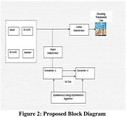
Figure 2: Proposed Block Diagram
The proposed block diagram of the unified power flow control which is mainly optimizing the transmission line sag and swells voltage and stabilizes the frequency oscillation. Since the diagram, it consists of reactive power compensation of the series transformer and shunt transformer with the proposed Spontaneous Energy Optimization (SEO) strategy for optimizing the power transmission reliability and stability. The general structure of proposed SEA based UPFC includes two inverters, and it is related to an inclination voltage generator as presented in this model.
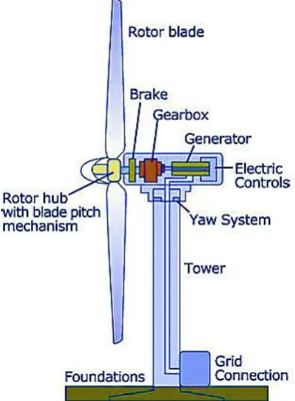
3.1 Wind Energy:
power which is extremely reliable from year to year yet which has a considerable variation over shorter timescales. It is in this manner utilized as a part of conjunction with other electric power sources to give a dependable supply. Also, weather forecasting permits the electrical power network to be readied for the predictable variations in production that occur
Figure 3: Wind Energy Generation System
3.2 Ac/Dc Converters:
The simplest AC/DC converters comprise of a transformer following the input filtering, which then passes onto a rectifier to produce DC. In this case, rectification occurs after the transformer because transformers do not pass DC. However, many AC/DC converters use more sophisticated, multi-stage conversion topologies as depicted due to advantages of smaller transformer requirements and lower noise referred back to the mains power supply.
Figure 4: AC/DC Converter
A converter is an electrical device composed of one or more diodes that convert alternating current (AC) to direct current (DC). A diode resembles a restricted valve that enables electrical current to stream.
3.3 BOOST CONVERTER:
used to increase the output voltage compared to the input voltage. Its output load has a DC-DC DC converter that steps up the voltage when its input supply is at the current end. A capacitor, inductor, or combined: It has a switched mode power supply (SMPS) with a diode with at least two semiconductors and a class with a transistor and at least one power saving element. To reduce the voltage ripple, the induction filters are sometimes combined with a converter output load side filter and input (supply side filter). The power switch for power switches, i.e., batteries, solar panels, rectifiers, and DC generators can come from any suitable DC sources. A DC to DC converter circuit is called a process that changes the DC voltage to different DC voltages. An output voltage shifted to a DC-DC, rather than a source of voltage.
Figure 5: Simple Boost Converter Circuit
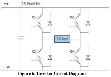
3.4 INVERTER:
An inverter has a motor control that adjusts an AC trigger motor speed. It does this in a variety of frequencies in motor AC power. An inverter also changes the voltage to the motor.
This process takes place using some complex electronic circulation that controls six separate power devices. They switch and turn simulated three-phase AC voltage. This transformation process is known as a DC bus for voltages and current to AC waveforms that are used in the motor. This name has led to "inverter." Throughout this discussion, the term "inverter" is used in the adjustable speed drive space.
Figure 6: Inverter Circuit Diagram
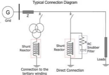
3. 5 Shunt Transformer:
To improve the stability and power transmission capacity, shunt reactors are involved in system systems. These long drive wires or cables are placed in a parallel structure to compensate for generic capacity currents depending on the line and reaction power balance load times.
Shunt reactor was similar to a power transformer in design and backup. Optimum reliability/charge efficiency and minimum life cycle cost, as well as rush currents, a straightforward and robust build-up, has been adopted.
high efficiency and transmission costs. We offer a wide range of three-stage reactors considering traffic limitations in Swift products and some countries according to customer requirements.
Figure 7: Shunt Transformer & Rector
3.6 Series Transformer:
A transformer connected to AC power supply the initial state will Surge current flow is restricted via the primary winding, called inrush current. This suddenly is like the start of the motor. When starting injects voltage to the transformer, the magnetic flux and current in the coil will start at zero and gradually increases transformer flux is approximate twice the maximum size of the normal because of the total area below the first half-circuit voltage waveform. Generation magnetomotive force (MMF) is more efficient than ordinary because the best transformer randomly increases the normal maximum magnetic current twice. Winding currents are generated by a change of magnetic flue that increases the maximum dose twice the maximum value. This is producing inrush current in transformers.
Figure 8: Series transformer
IV.
HARDWARE IMPLEMENTATION:
This model focuses a single phase UPFC and simulates it using MATLAB and Simulink software. A lab-scale model will then be constructed, and its performance is compared to the simulated ones. The effect of phase shift, φ of VS to the supply voltage, V1 is investigated. Based on the schematic diagram of the three-phase UPFC in Figure 14, a simulation model of a single three-phase UPFC is drawn in Simulink and is illustrated. Series and shunt converter, which are connected with a common DC connection. A switch or static synchronous series compensator (SSSC) is used to provide the reaction power on the AC system, as it is used to replace the exterior or fixed synchronization of the AC system, as it is used to add control voltage and phase angle by the voltage in the line sequence, as it gives the DC power inverter. In these two branches consists of a power electronic converter and transformer.
4.1 Hardware Model:
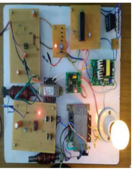
Figure 10: Hardware model for proposed system.
Figure 10 represents the proposed Hardware for the Power Quality Improvement for Grid Connected Wind Energy System Using Unified Power Flow Controller,mainly in this system consists of AC source, Rectifier, DC to DC converter, Inverter, Traic, Controller, and load system.
In this system to compensate the output voltage with help of the UPFC based on SEOA technique, if any oscillation is occur in the output of the power system the controller is given the pulse to converter and compensating the output voltage.
The shunt and series transformer is used in this system and compensate the voltage. The controller analysis the voltage and give the modified pulse to the inverter circuit and compensate the load voltage with help of the proposed system
4.2 Hardware Output
Hardware Specification Input Ranges
Output Ranges
Source Input power Grid
power
12v AC
Rectifier Input power 12v AC 12v DC
DC to DC
Converter
Input power 12v DC 24v DC
Inverter Input power 12v DC 230V AC
Microcontroller PIC (16f877a) 5V DC 5V DC
Traic Input power 0-230v 230v
4.3 Advantages:
Control of power flow Reduce reactive power flow, thus allowing the lines to carry more active power. Increase the load capacity to their thermal capabilities.
Increase the system stability through raising the transient stability limit. 4.4 Applications:
Used for optimal power flow control.
Increase transient stability of inter-area power system.
Use for damping power system oscillation for improving micro grid voltage profile Use in HVDC transmission system.
V.
RESULTS AND DISCUSSION:
The present modelling approach of a Mat lab-based toolbox for developing and testing the UPFC using Algorithm Spontaneous Energy Optimization Algorithm (SEO) under various operational conditions. The proposed model is designed in a mat lab environment.
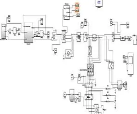
Figure 11: Simulation Circuit Diagram for the Proposed Method.
The overall simulation circuit diagram for the proposed method.
5.1 Wind Waveform:
Figure 12: Wind Waveform
5.2 Boost converter waveform:
Figure 13: Boost Converter Waveform
The above figure. Shows the boost converter (DC to DC) output waveform. It increases the input voltage up to double or above than generated voltage.
5.3 Output waveform:
Figure 14: output waveform
The above Figure 14 shows the overall output waveform of the proposed method. In the proposed method, a new algorithm is used Spontaneous Energy Optimization (SEO) to improve the output gain.
5.4 THD Analysis:
Figure 15: THD analysis
VI.
CONCLUSION
The structure of the proposed reference voltage and current estimator allows the compensation of the reactive power at the fundamental grid frequency, voltage, and currents harmonics simultaneously and mitigates voltage dips and over-voltages. Moreover, the disturbance compensation levels can be configured allowing a more flexible operation. The proposed controller performance is evaluated by the process and is evaluated using simulated tests. And the Simulated results are considered the proposed controller efficiency and satisfactory performance in dealing with such areas. The future work should be aimed at the extension of the new approach proposed by the power system for power oscillation damping.
REFERENCES
[1]. Xiangping Kong, Yubo Yuan, Lei Gao, Peng Li, Qun Li, " A Three-Zone Distance Protection Scheme Capable of coping with the Impact Of UPFC," IEEE Transactions On Power Delivery, Pp. 0885-8977, 2017
[2]. Sajjad Golshannavaz, Farrokh Aminifar, Daryoush Nazarpour, “Application of UPFC to Enhancing Oscillatory Response of Series-Compensated Wind Farm Integrations," IEEE Transactions on Smart Grid, Vol. 5, No. 4, July 2014
[3]. S. S. Choi, B. H. Li, and D. M. Vilathgamuwa, “Dynamic Voltage Restoration with Minimum Energy Injection," IEEE Transactions. On Power System, Vol. 15, pp. 51–57.
[4]. J. G. Nielsen, M. Newman, H. Nielsen And F. Blaabjerg, “Control And Testing Of A Dynamic Voltage Restorer (DVR) At Medium Voltage Level," IEEE Trans. Power Electronics. Vol. 19, No. 3, pp. 806-813, 2004.
[5]. Mohammad Ferdosian, Hamdi Abdi, Ali Bazaei, “Improving the Wind Energy Conversion System Dynamics during Fault Ride through UPFC versus Statcom," IEEE International Conference on Industrial Technology (Icit), 2015.
[6]. Manas Kumar Jena, Subhransu Ranjan Samantaray, “Data-Mining-Based Intelligent Differential Relaying For Transmission Lines Including UPFC and Wind Farms," IEEE Transactions on Neural Networks and Learning Systems, Vol. 27, No. 1, January 2016 [7]. Varaha Satya Bharath Kurukuru, Mohammed Ali Khan, Rupam Singh, “Performance Optimization of UPFC Assisted Hybrid
Power System," IEEE Engineer Infinite Conference, 2018
[8]. Paital, S. R., Patra, S., Singh, A. K., Mohanty, A., & Ray, P. K. “Reactive Power Compensation Using PSO Controlled UPFC In A Microgrid With A DFIG Based WECS." Annual IEEE India Conference (Indicon), 2015.
[9]. Shrawane, S. S., Diagavane, M., & Bawane, N. “Concoction Of UPFC For Optimal Reactive Power Dispatch Using Hybrid Gapso Approach For Power Loss Minimization." IEEE Power India International Conference (Piicon). 2014
[10]. Xiaohui, Y., Yunlong, F., Haifeng, L., Hang, M., Xinli, S., Wenzhuo, L., & Yan, Z. “Electromechanical Transient And Electromagnetic Transient Hybrid Modeling And Simulation Of MMC-UPFC Project." IEEE Conference on Industrial Electronics and Applications (ICIEA), 2018
[11]. Dr.R.Sankarganesh, M. Ilango, “Simple Four-Quadrant Grid-Tie Fuzzy Logic Control Scheme with Single-Phase DC / AC Converters,” Excel Int. J. Technol. Eng. Manag., vol. 5, no. 2, pp. 36–41, 2018.
[12]. S.Chinnasamy, R.Sankarganesh, “Power Quality Improvement Of Grid Tied Pv With Reduced Number Of Components For Standalone Application,” Int. J. Emerg. Technol. Comput. Sci. Electron., vol. 21, no. 2, pp. 291–296, 2016.
[13]. T.Murugan, R.Sankarganesh, “Power Quality Improvement For Harmonic Elimination Of Variable Frequency Drive,” Int. J. Emerg. Technol. Comput. Sci. Electron., vol. 21, no. 2, pp. 287–290, 2016.
[14]. D.Srinivasan, R.Sankarganesh, “Super Capacitor For Harmonic And Power Factor Compensation,” Int. J. Emerg. Technol. Comput. Sci. Electron., vol. 22, no. 1, pp. 129–133, 2016.
[15]. Dr.R.Sankarganesh, S.Kannan and K.Karthikeyan, "Improvement of Power Conversion Efficiency of a DC-DC Buck-Boost Converter with Snubber Circuit," Int. J. Pure Appl. Math., vol. 120, no. 6, pp. 9999–10014, 2018.