http://www.sciencepublishinggroup.com/j/ijcems doi: 10.11648/j.ijcems.20190501.14
ISSN: 2469-8024 (Print); ISSN: 2469-8032 (Online)
Implementation and Evaluation of WS531-2017
"Specification for Testing of Quality Control in Helical
Tomotherapy Unit"
Cheng Xiaolong, Liu Jiping
*, Shi Jianfang
Department of Radiation Physics, Zhejiang Cancer Hospital, Hangzhou, China
Email address:
*
Corresponding author
To cite this article:
Cheng Xiaolong, Liu Jiping, Shi Jianfang. Implementation and Evaluation of WS531-2017 "Specification for Testing of Quality Control in Helical Tomotherapy Unit". International Journal of Clinical and Experimental Medical Sciences. Vol. 5, No. 1, 2019, pp. 14-18. doi: 10.11648/j.ijcems.20190501.14
Received: March 17, 2019; Accepted: April 26, 2019; Published: May 15, 2019
Abstract:
Objective: To perform an annual test on the system stability of the first helical tomotherapy unit (Tomotherapy, TOMO) in Zhejiang province according to WS531-2017 "specification for testing of quality control in helical tomotherapy unit", and to further standardize the quality control operation, understand the properties of the system and ensure the accurate implementation of clinical radiotherapy. Methods: According to the requirements of WS531-2017, 8-channel measurement instrument (TomoElectrometer), ionization chamber A1SL (Standing Imaging, USA) and A17 (Standing Imaging, USA), cylindrical phantom (Cheese Phantom), equivalent rectangular solid water, two-dimensional water tank, EBT3 film, and Vidar film analyzer were used to detect 10 key indicators of TOMO. Results: The static output dose deviation was -0.6%, and the rotational output dose deviation was 1.4%. The difference between radiation quality and planned value was 0.8%. The symmetry of the horizontal dose curve of the radiation field was -1.2%; and the full width at half-maximum deviation of the longitudinal dose curve of the radiation field was 0.7mm. The horizontal offset of multi-leaf collimator was -0.6mm. The green laser offset in axial plane, sagittal plane and coronal plane were 0.08mm, 0.2mm and 0.2mm to the of virtual isocenter. The red laser light offset was -0.4mm. The movement deviation of the treatment bed was 0.3mm; and the synchronous deviation of the rotation of the treatment bed and frame was -0.6mm. Conclusion: All 10 key indicators of TOMO meet the requirement of WS531-2017. Some necessary testing items, such as MVCT image quality verification, should be added to the annual TOMO quality control in order to ensure the good stability and normal working of system.Keywords: Helical Tomotherapy Unit, Quality Assurance, Radiotherapy Dose, Deviation
1. Introduction
The helical TomoTherapy unit (TOMO) is a modality for the delivery of inverse planned intensity modulated radiation therapy (IMRT), together with a highly integrated image-guided approach [1]. It combines the main characteristics of a linear accelerator and a CT scanner, which provides helical delivery of radiation through a rotating gantry and translating couch [2]. The radiation beam used for imaging is generated by the same linear accelerator that is used for generating treatment beam. The imaging accuracy and irradiation accuracy are both 0.1mm, much higher than the traditional linear accelerator (1cm) [3]. The megavoltage
CT (MVCT) provides the ability to acquire CT images of the patient in treatment position and using this information for image guidance. In addition, the reconstructed MVCT values are potentially useful for treatment planning inhomogeneity corrections and dose reconstruction [4]. During a helical tomotherapy each rotation is divided into 51 sections, a binary MLC is used for fluence modulation. The 64 pneumatically driven leaves of the MLC are either completely open or closed [5]. The maximum target range of treatment can reach 60×160cm2, which has redefined the standard for individualized and precise treatment of tumors anywhere in the body [6].
of the helical tomotherapy unit and its implications in routine clinical practice, the Therapy Physics Committee (TPC) of the American Association of Physicists in Medicine (AAPM) commissioned Task Group 148 (TG-148) to review this modality and make recommendations for quality assurance related methodologies [7]. Currently, more than 600 units have been installed worldwide and more than 40 units in China. It is anticipated that additional TOMO techniques will be developed in the future, which is closely related to its independent and comprehensive quality assurance program. The testing of quality assurance for TOMO should include acceptance test, status test, and constancy test. The implementation of WS531-2017 "specification for testing of quality control in helical tomotherapy unit" provides a standard for the quality control of TOMO system in China. In this study, the stability test of the first TOMO in Zhejiang province was carried out in combination with this standard, and the standardized operation, error and data analysis of each test item were elaborated to provide technical support for the promotion of this standard.
2. Material and Method
2.1. Material
HI-ART Tomotherapy System, Operator Station, Planning Station, Virtual Water Cheese Phantom, Solid Water Plates, TomoElectrometer, A1SL Ionization Chamber, A17 Ionization Chamber, Water Tank, 2D Scanning Arm, TomoScanner Scan Arm Controller, PC with TomoTherapy Electrometer Measurement System (TEMS) Software, RS485 Cables, GAFCHROMIC EBT3 Film, Vidar Film Digitizers, Thermobarometer, Toolkit, et al. All of the materials were calibrated and measured by National Institute of Metrology, China.
2.2. Method
Several necessary operations should be done before each QA test: (1) Turn the machine on and wait until the machine water temperature reaches 40°C (2) Run a 5 minutes warm-up procedure (3) Run an air scan procedure.
2.2.1. Static Output Dose Test
For the stationary procedure, the gantry is positioned at 0° with a 40×5cm2 static field. In figure 1, two solid water plates are positioned at virtual isocenter, the ion chamber is inserted into the plate at a depth of 1.5cm with a source-skin-distance (SSD) of 85cm. The ionization chamber is connected with the electrometer, read the temperature and air pressure values, ensure the normal function of the instrument. Run the stationary procedure, record the electrometer measurement data and calculate the absorbed dose, then compare with the nominal value, the output consistency should within 2% window.
2.2.2. Rotational Output Dose Test
The rotational procedure that mimics a patient treatment, which should create IMRT plan on the cheese phantom in the
treatment planning system (TPS). Run the rotational procedure. Set up phantom according to the planned conditions and insert the ion chamber into the measuring hole like the figure 2. The absorbed dose was read and calculated according to the static output dose test method and compared with the dose value of the treatment plan, the output consistency should within 4% window.
Figure 1. Setup of static output dose detection.
Figure 2. Setup of rotational output dose detection.
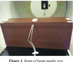
2.2.3. Beam Quality Test (Percentage Depth Dose, PDD) Use the stationary procedure as the test program, the solid water plates are positioned as the figure 3, with a PDD of 85cm. Two ionization Chambers should be inserted into the uppermost solid water plate holes at first, a fixed ion chamber is used to measure the dose at the depth of 1.5cm, at the same time the other ion chamber is used for measuring the dose at the depth of 1.5, 10, and 20cm, respectively, and the holes will be filled with Virtual Water plugs. Run the program three times respectively, read and calculate according to the static output dose test method, calculate PDD10 and PDD20 then compare with the gold data, the output consistency should within 3% window.
Figure 3. Setup of beam quality test.
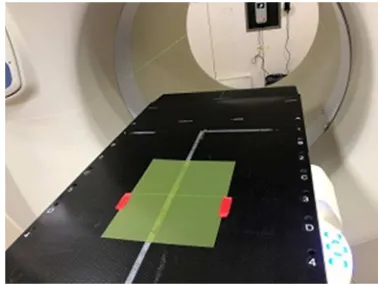
2.2.4. Transverse Beam Profile and Longitudinal Beam Profile Test
fill tank with deionized water (25cm depth or about 1cm above handles). Set the gantry position at 0° with a 40×5cm2 static field, the water tank is positioned as the figure 4. Run the test program and operate the Electrometer Measurement software in the dedicated computer, the transverse beam profile is measure and the data is acquired at an SSD of 85cm with the depth of 1.5cm. Turn the 2D tank 90°, use the same operation, the longitudinal beam profile is measure and the data is acquired at an SSD of 85cm with the depth of 1.5cm. The tolerance limit of the transverse beam profile is 1% average difference in field, and the value of the longitudinal beam profile (each slice width) is 1% of slice width at FWHM.
Figure 4. Setup of water tank test.
2.2.5. Multi-Leaf Collimator (MLC) Alignment Test
A film is positioned horizontally between solid water plates (depth of 2cm) and is positioned below the isocenter that is defined by stationary green lasers like the figure 5. Run the program, two central MLC leaves (32 and 33) are opened in addition to two off-center leaves (27 and 28). First, the film is exposed with the gantry at 0°. Second, the gantry is move to 180° and only the two off-center leaves are opened. Analyze the film by Vidar Film Digitizers, the MLC offset should be less than 1.5mm at the isocenter.
Figure 5. Setup of MLC alignment test.
2.2.6. Green Laser Localization Test
Align the center of the cheese phantom with the green laser, scan with MVCT, determine the deviation of the green laser on the Z-axis and X-axis by software on operator station. A film is positioned horizontally between solid water plates and is positioned below the isocenter that is defined by stationary green lasers like the figure 6. Run the program, the filed width in Y-axis is 1cm. Analyze the film, the center of the radiation field should agree with the laser position to within 1mm.
(a)
(b)
Figure 6. Setup of the green laser localization test.
2.2.7. Red Laser Localization Test
Place the red laser in the initial position within the range of 20cm from the virtual isocenter, and check its coincidence with the green laser by the coordinate paper, the deviation should within 1mm.
2.2.8. Couch Movement Accuracy
2.2.9. Couch Translation and Gantry Rotation Synchronism Adjusting the couth so that the Z-axis green laser passes over the surface. A film with 1.5cm buildup is positioned at isocenter. A rotational irradiation is used with the nominal 1cm beam and a pitch of 1 for 13 rotations. The control sinogram is set to open all the levels for half a rotation on the 2th, 7th, and 12th rotation. The resulting profile should show maxima 5cm apart to within 1mm.
Figure 7. Synchronism of couch translation and gantry rotation.
3. Result
In accord with WS531-2017 and TG-148 recommendations, all 10 key indicators of TOMO in Zhejiang Cancer Hospital can meet the requirements of WS531-2017, the specific results are shown in table 1.
Table 1. Comparison of test results and evaluation values of TOMO.
Serial
number Item
Tolerance limit
Measured value
1 Static output dose -2.0%~2.0% -0.6% 2 Rotational output dose -4.0%~4.0% 1.4% 3 Beam quality (PDD) -3.0%~3.0% 0.8% 4 Beam field transverse profile -3.0%~3.0% -1.2% 5 Beam field longitudinal profile -1.5mm~1.5mm 0.7mm 6 MLC lateral offset -1.5mm~1.5mm -0.6mm 7 Green laser alignment accuracy -1.0mm~1.0mm 0.08mm 8 Red laser alignment accuracy -1.0mm~1.0mm -0.4mm 9 Couch movement accuracy -1.0mm~1.0mm 0.3mm
10 Couch translation and gantry
rotation synchronism -1.0mm~1.0mm -0.6mm
4. Discussion
The static output, the rotational output and laser localization should be monitored on a daily basis. In accord with the recommendations of AAPM TG-51 report, the dose of beam output can be calculated using the following equation [8]:
D
cGy=Pctp⋅ ⋅C Ccf ⋅Ecf (1)
ctp deg
P =((273.2+C ree) / 295.2) (101.33 /× Pbar) (2)
where Pctp is the correction of temperature and pressure,C is the ionization readings with the unit of nC, Ccf is the ionization calibration factor with the unit of cGy/C, Ecf is the
electrometer correction factor, Cdegree and Pbar are the temperature and air pressure in the treatment room separately [9]. For the stationary procedure, the gantry is stationary and a treatment field can be delivered for a specified time. Since the dose rate is initially unstable, all MLC leaves should be closed for at least the first 10s of this procedure. Run the program 5 times and calculate the average value. Most user currently use the patient plan DQA replace the rotational output test. In this process, use an ionization chamber measure a single point dose and compare with the dose calculated with the TPS [10]. If the measured results of static output and rotational output are outside the tolerance level, the clinical physicist needs to investigate, the reason maybe as follows: (1) A deviation in beam quality (2) MLC leaf latency, which include pressure change, dust attached, leaf rust, leaf wear, and so on. Two solutions can be adopted [11]: (1) adjust the beam quality (2) adjust air pressure of air compressor, add dehumidifier devices, MLC maintenance and replacement, remeasure the MLC leaf latency data. At initialization, the green laser and red lasers should coincide within 1mm, which should be test daily. As the two kind of lasers are independent of each other, if the daily test show that the two systems do not coincide upon system initialization, the physicist should make sure which one needs to be adjusted.
Beam quality, green laser alignment accuracy and couch movement accuracy tests are the content of monthly test. The best method for the beam quality (PDD) test is adopting water tanker, which is recommended for annual tests. The monthly test of beam quality is determined in a series of water plats with a simultaneous measurement of the dose at three depths of 1.5cm, 10cm and 20cm. The green lasers and red lasers are independent of each other, the green lasers system is fixed and used for projecting lase line to the virtual isocenter. The correct initialization of the lasers should be check daily, if the two lasers do not coincide within the tolerance limit, which of the two lasers has changed should be investigated and corrected. The couch movement test of physical distances and digital readout should be done on a monthly basis. The couch should be loaded 70kg weight from A point to J point uniformly.
modulation is achieved by leaf specific opening times. There is no flattening filter, much smaller SSD and higher output dose rate, compared with the C-arm type accelerator [12]. The unique technology of TOMO require much higher and more precise on QA. The test condition of couch translation and gantry rotation synchronism is empty couch in the WS531-2017, it is suggested that the test maybe much more accurate when the couch is loaded with 70kg weight based on the communicating with factory engineer and work experience.
5. Conclusion
Task Group 148 provides a comprehensive set of recommendations on all aspects of TOMO that should be tested. The national standard WS531-2017 of China is based on the TG-148. Although the content of QA has been simplified, the core indicators of TOMO are included, which can raise the QA efficiency. The 10 key indicators of TOMO are tested in this study, and the result can meet the technical requirements. At the same time, some questions are found. The QA tests for TOMO should include mechanical alignment, beam parameters, synchronicity, and image quality [13, 14]. Well the WS531-2017 dose not cover the image quality test, and the test about MLC is much less. The QA tests of tongue and groove (T&G) effect, y-jaw divergence/beam centering, y-jaw/gantry rotation plane alignment and treatment field centering should be added. TOMO is a relatively new modality with integrated treatment planning and delivery hardware for radiation therapy treatment. Due to the unique treatment method and complicated structures, it is essential to ensure the TOMO with normal operation and fine stability [15]. It is suggested that each TOMO unit should add some necessary test items except the WS532-2017 QA recommendations in TOMO annual test.
Acknowledgements
This study was supported by Zhejiang medical and health science and technology project (2018PY004) and Zhejiang key laboratory of radiation oncology.
References
[1] Li Y, Xu H J. The modern physics of radiation oncology [M]. Beijing: China Atomic Energy Press, 2015.
[2] Sen A, West M K. Commissioning experience and quality assurance of helical tomotherapy machines [J]. Journal of Medical Physics, 2009, 34(4): 194-199.
[3] Mackie T R. History of tomotherapy [J]. Physics in Medicine & Biology, 2006, 51(13): 427-453.
[4] Ruchala K J, Olivera G H, Schloesser E A, et al. Megavoltage CT on a tomotherapy system. [J]. Physics in Medicine & Biology, 1999, 44(10): 2597-2603.
[5] Ricchetti F, Barra S, Agostinelli S, et al. Feasibility of helical tomotherapy for radical dose retreatment in pelvic area: a report of 4 cases.[J]. Tumori, 2011, 97(4): 492.
[6] Chen Q, Westerly D, Fang Z, et al. TomoTherapy MLC verification using exit detector data [J]. Medical Physics, 2012, 39(1): 143-151.
[7] Langen K M, Papanikolaou N, Balog J, et al. QA for helical tomotherapy: Report of the AAPM Task Group 148a [J]. Medical Physics, 2010, 37(9): 4817-4853.
[8] Jeraj R, Mackie T R, Balog J, et al. Dose calibration of nonconventional treatment systems applied to helical tomotherapy [J]. Medical Physics, 2005, 32(2): 570-577. [9] Kapatoes J M, Olivera G H, Ruchala K J, et al. A feasible
method for clinical delivery verification and dose reconstruction in tomotherapy [J]. Medical Physics, 2001, 28(4): 528-542.
[10] Chen Q, Levinson L, Ding K, et al. TomoTherapy Patient QA Using Exit Detector Measurement of Pre-Treatment In-Air Delivery [J]. Medical Physics, 2012, 39(9): 3707-3707. [11] Chen Q, Westerly D, Fang Z, et al. TomoTherapy MLC
verification using exit detector data. [J]. Medical Physics, 2012, 39(1): 143-151
[12] Fenwick J D, Tomé W A, Jaradat H A, et al. Quality assurance of a helical tomotherapy machine [J]. Physics in Medicine & Biology, 2004, 49 (13): 2933-2953.
[13] Klein E E, Joseph H, John B, et al. Task Group 142 report: Quality assurance of medical accelerators [J]. Medical Physics, 2009, 36(9): 4197-4207.
[14] Fenwick J D, Tomé W A, Jaradat H A, et al. Quality assurance of a helical tomotherapy machine. [J]. Physics in Medicine & Biology, 2004, 49(13): 2933-2953.