1578
Effects Of Voltage Imbalance In Three Phase
Controlled Rectifier Based System
N.Priyadharshini, N.B. Pavatharini, R.K.Prasanth, C.S.Sasidharan, M.Mohanraj
Abstract—The evolution of semi-conductor switches has resulted in their increased use in electrical and electronic devices in recent trends. The growing use of thyristor-based rectifiers has caused the power grid to face severe harmonic problems. In power systems, voltage unbalance occurs often. The primary source is uneven distribution of single-phase loads throughout all phases. If a three-phase fully controlled rectifier is connected with an unbalanced grid it results in voltage ripple. In this project the analysis of three phase rectifier with resistive load is done. Simulation is done in MATLAB with various voltage imbalances and the ripple factor is found. The hardware analysis is also done with voltage unbalance and the output ripple factor is analyzed. The analysis shows that the unbalance in the input voltage increases the switching losses and voltage ripple. This influences the switch conductive intervals and further distorts the input current waveform.
Index Terms— Firing angle, harmonics, Ripple factor, switching losses, Voltage Imbalance. —————————— ——————————
1 I
NTRODUCTIONPower electronics is the major application of solid-state electronics to control and conversion of electric power. The most common power electronic devices, that are used in many consumer electronic devices, such as television sets, personal computers, UPS (uninterrupted power system), etc. Industrial applications include paper mills, steel mills, compressors, pumps, blowers, etc. Power system applications include high voltage and low voltage panels control process, generation systems such as solar, wind, power transmission and distribution systems, PLC and SCADA, energy storage systems, etc. Rectifiers are often found as a component of DC power supplies and High-Voltage Direct Current power transmission systems. Based on AC input supply, additional smoothing may be demanded to produce a uniform steady output voltage. Electronic filters like capacitors, choke, set of capacitors, etc are used to ensure steady and pure DC output. Rectifiers are ac to dc power converters that converts fixed ac supply voltage and frequency into a variable dc output voltage. The controlled rectifiers are widely used in metallurgical and chemical processes, reactors, power supplies, portable instrument drives, flexible industrial drives, etc. Voltage unbalances are related with current and voltages variations of power systems when the magnitudes of phase voltage or phase angles are unequal between the phases. The voltage unbalance occurs frequently because the single-phase loads get distributed unevenly across three-phase power systems. This even occurs due to a more number of
single-phase loading, such that if any of the fuses is not working for three-phase motors. Voltage imbalances can results in overheating inside the windings of synchronous and induction machines. A method of dual current regulation is adopted to control voltage imbalance by analyzing the instant active power and reactive power of the system [1]. Input power regulation is the best and efficient methods to increase the efficiency of a PWM rectifier operating under unbalanced input supply-voltage conditions [2].Output-power-control method, in which the current commands, given by linear equations are estimated so as to distribute the input power suitably to maintain the dc output voltage and sinusoidal line currents as constant. Circuit topology method is used to convert AC to DC power with increased voltage output and decreased switching losses in MATLAB and results are evaluated [3]. Unity power factor, low supply side THD and sinusoidal input current are ensured. There is a conversion of a 230V AC to 400V DC with a 50 percent reduction in voltage stress around the switches. The mathematical model for analyzing a three-phase voltage source rectifier (VSR) and MATLAB/ Simulink model for full control three-phase bridge rectifier is discussed [4], AC to DC conversion is done with PWM technique, which involves modulation index with fixed frequency. New technique for Pulse Width Modulation controlled rectifier which achieves unity power factor on input ac side and reduction of ripple on output dc side [5]. Ripple current on DC line is reduced and so large capacitors and LC resonant circuits are not required.
2
M
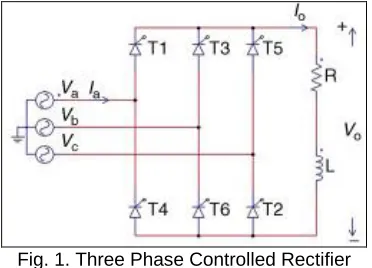
ATHEMATICAL MODELLINGThree phase converter is a fully controlled bridge rectifier configuration with RL load is shown in figure 1. All the switches are controlled and each switch gets turned ON and OFF based on the gate trigger signals applied to the rectifier. Its applications are mainly in industrial areas, where 120 kW output power is demanded and also used where two quadrant operation is required. The output ripple voltage has a frequency of 6fs. Less filtering is required when compared with that of three phase semi and half wave converters. The thyristors switches are triggered with firing angle at an interval of 30°.
————————————————
Fig. 1. Three Phase Controlled Rectifier
At ωt=(π/6 +α), firing pulse is given and the thyristor is turned on and continue to conduct untill the gate signal is turned off. The line voltage appears across the load when thyristors conduct during the time period ωt=(π/6 +α) to (π/2 +α). At ωt=(π/2 +α), the T2 is triggers on due to forward bias and T6 is turned off due to natural commutation since reverse biased. Switches T1 and T2 conduct simultaneously and the line voltage appears at load terminals during the time period ωt=(π/ +α) to (5π/6 +α). Each thyristor is given with a number, corresponding to which they are triggered. 12, 23, 34, 45, 56, 61, 12, 23 and so on are the triggering sequence. As per above sequence, when two switches are turned ON means the remaining will be switched off.
The line-to-neutral voltages are defined as
Van= Vmsinωt (1) Vbn=Vmsin (ωt-2π/3) (2) Vcn=Vmsin (ωt+2π/3) (3)
The corresponding line-to-line voltages are
Vab= √3Vmsin (ωt+30) (4) Vbc= 3Vmsin (ωt-90) (5) Vca= 3Vmsin (ωt+90) (6)
The output voltage average is found from
Vdc= [3√3Vm/π] cosα (7)
Output current is assumed constant at Io, the rms value of source current is
Is =Io √2/3 (8)
Each IGBT conducts for 120 degree. Therefore, rms value of thyristor current is
ITh = Io√1/3 (9)
The average value of the output current= Io/3
3
V
OLTAGEI
MBALANCEThe issues of power supply that often affect industries involve voltage sags and swells, transients, harmonics,voltage and current imbalance. The phase voltages magnitude should be equivalent or very similar in a balanced power system. In power system voltage unbalance is a function of the phase
voltage imbalance and also measures the voltage variations between the phases of a three-phase input supply system. This affects the performance of three-phase motors and reduces their lifespan. Due to unbalanced voltage source, third harmonic current and second harmonic voltage components are produced as additional components. The effects of voltage imbalance were studied with modulation magnitude and phase angle control [6]. The analysis is focused on the dynamic transformation of the d-q-n synchronous frame of reference and the technique of harmonic balance.
Voltage Imbalance between the split capacitors in three-phase half-bridge switch-mode rectifiers is observed and the elimination of the imbalance by adding a DC bias to the source current of each phase[7].The imbalance in voltage between the dual output DC voltages of a half-bridge boost rectifier with mismatched loads is analyzed and compensating signal proportional to the voltage difference is added in the current command to eliminate the voltage imbalance and adverse effects of the compensating current to the input power factor are discussed[8].
4 SIMULINK MODEL OF THE RECTIFIER
Fig. 2 Simulink model of Three Phase Controlled Rectifier
The simulation module is established through MATLAB/Simulink and the corresponding voltage waveforms obtained. The various input voltages are given and the corresponding voltages and ripples have been analyzed. The simulink model for the three phase fully controlled rectifier with the RL load is shown in figure 2.
The thyristor conduction starts only after 30 degree, till that it is OFF condition. After that 60 degree firing angle is given to each switch. Based on firing angle, ON-OFF switching sequences are calculated for the switches using the Equation (10). The rectifier is analysed with both balanced and unbalanced output
ON time=((30+α)/360)*(0.02) (10)
5
BALANCED VOLTAGE ANALYSIS1580 Ripple Factor=(0.3 Vm)/Vdc (11)
Where,
Vdc=(2Vm )/π(13) (12)
Fig. 3 Output voltage for balanced input 250 V
6
UNBALANCED VOLTAGE ANALYSISUnbalanced inputs are given to the rectifier with difference in magnitude in all the phases. Table 1 shows the different voltage magnitude given to the rectifier and its output voltage magnitude. Figure 4 shows the output voltage for the unbalanced case III. The ripple factor is also analyzed for the different cases. Table 2 shows the comparison of ripple for balanced and unbalanced output voltages. the ripple factor got increased due to the presence of unbalance in the supply voltage.
Fig. 4 Output voltage for unbalanced input 150V,100V,50V.
TABLE 1
UNBALANCED INPUT AND OUTPUT VOLTAGES
TABLE 2
RIPPLE FACTOR FOR BALANCED AND UNBALANCED INPUT
7
HARDWARE MODELHardware implementation is made in small scale and it is inferred from that the output voltages of both simulation and hardware are almost same and both voltage and current ripple are also nearly equal to each other. Figure 5 shows the rectifier circuit of the hardware model.
Fig. 5 Rectifier circuit of the model.
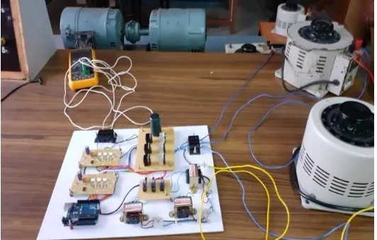
voltage in a circuit relatively close to a desired value. Figure 6 shows the hardware setup model of the three phase rectifier.
Fig. 6 Hardware setup of three phase rectifier.
8 CONCLUSION
In this paper design and analysis of three phase controlled rectifier is done. In MATLAB, simulation was done on three phase rectifier with unbalanced three phase inputs, corresponding outputs are obtained. The output was not a pure DC since there was certain level of ripples. The ripple factor was calculated from the output waveform. Even though the input voltages vary, the designed rectifier gives the DC output with constant ripple. The three phase controlled rectifier has been designed and the necessary hardware has been developed. The various unbalanced input is given to the rectifier using autotransformer and the corresponding outputs were obtained. The prototype model of three phase controlled rectifier is analyzed with various AC input voltages using auto transformer and the outputs were obtained. Due to input variation, pure DC is not obtained, both output voltage and output current have certain amount of ripple. The output voltage is analyzed through multimeter. Initially before giving input supply, capacitor discharge can be detected and input given is added to capacitor discharge value and output is obtained.
R
EFERENCES[1] Jinghua Zhou, Qingliang Hou, Xiaowei Zhang, Zhengxi Li. “A Control Method of Three-Level PWM Rectifier Under the Imbalanced Three-Phase Grid Voltage”. 2010 2nd IEEE International Symposium on Power Electronics for Distributed Generation Systems.
[2] Bo Yin, Student Member, IEEE, Ramesh Oruganti, Senior Member, IEEE,Sanjib Kumar Panda, Senior Member, IEEE, and Ashoka K. S. Bhat, Fellow, IEEE. “An Output-Power-Control Strategy for a Three-Phase PWM Rectifier Under Unbalanced Supply Conditions”. IEEE Transactions on industrial electronics, vol. 55, no. 5, may 2008.
[3] DamodharReddya, Sudha Ramasamya. “Design of a Three-phase Boost Type Vienna Rectifier for 1kW Wind Energy Conversion System”, International journal of renewable energy, Vol.7, No.4, 2017.
[4] Aakash Singh, Aftab Alam. “A New Mathematical
Technique and Analysis of a Three-phase Voltage Source Rectifier”. 2017 International Conference on Innovations in information Embedded and Communication Systems (ICIIECS).
[5] Toshihisa Shimizu, Member, IEEE, Tsutomu Fujita, Gunji Kimura, Member, IEEE, and Jun Hirose. “A Unity Power Factor PWM Rectifier with DC Ripple Compensation”. IEEE Transactions on industrial electronics, vol. 44, no. 4, august 1997.
[6] Olorunfemi Ojo, Ishwar Bhat.” Influence of Input Supply Voltage Unbalances on thePerformance of AC/DC Buck Rectifiers”. Center for Electric Power , Tennessee Technological University, Cookeville, TN 38505.
[7] Moran L, Ziogas P D, Joos G. “Design Aspects of Synchronous PWM Rectifier-Inverter Systems under Unbalanced Input Voltage Conditions[J]”. IEEE Trans. On Industry Applications, 1992, 28(6): 1286-1293.
[8] Rioual P, Pouliquen H, Louis J P. “Regulation of a PWM Rectifier in the Unbalanced Network State Using a Generalized Model[J]”. IEEE Trans. on Power Electronics, 1996, 11(3): 495-502.
[9] Yongsug Suh, Lipo T A. “Control Scheme in Hybrid Synchronous Stationary Frame for PWM AC/DC Converter under Generalized Unbalanced Operating Conditions[J]”. IEEE Trans. on Industry Applications, 2006, 42(3): 825-835.
[10]M. Liserre, R. Teodorescu, and F. Blaabjerg, “Multiple harmonics control for three-phase grid converter systems with the use of PI-RES current controller in a rotating frame,” IEEE Trans. Power Electronics., vol. 21, no. 3, pp. 836–841, May 2006.
[11]L. Yacoubi, K. Al-Haddad, L.-A. Dessaint, and F. Fnaiech, “Linear and nonlinear control techniques for a three-phase three-level NPC boost rectifier,” IEEE Trans. Industrial. Electronics, vol. 53, no. 6, pp. 1908–1918, Dec. 2006. [12]B. Yin, R. Oruganti, S. K. Panda, and A. K. S. Bhat,
“Experimental verification of a dual input single-output (SISO) model of a three-phase boost-type PWM rectifier,” in Proc. 31st IEEE Conf. Ind. Electron.Soc., Raleigh, NC, 2005, pp. 1030–1035.
[13]B. Yin, R. Oruganti, S. K. Panda, and A. K. S. Bhat, “Performance comparison of voltage mode control and current mode control of a three-phase PWM rectifier based on dual SISO model,” in Proc. 32nd IEEE Conf. Ind. Electron. Soc., Paris, France, Nov. 2006, pp. 1908– 1914.
[14]D.-C. Lee and Y.-S. Kim, “Control of single-phase-to-three-phase AC/DC/AC PWM converters for induction motor drives,” IEEE Transactions Industrial Electronics, vol. 54, no. 2, pp. 797–804, Apr. 2007.
[15]IEEE Recommended Practice for Monitoring Electric Power Quality, IEEE Standard 1159-1995, 1995.
1582 loads,” IEEE Transactions Industrial Electronics, vol. 53,
no. 5, pp. 1612–1620, Oct. 2004.
[17]I. Etxebermia-Otadui, U. Viscarret, M. Caballero, A. Rufer, and S. Bacha, “New optimized PWM VSC control structures and strategies under un- balanced voltage transients,” ,” IEEE Transactions Industrial Electronics, vol. 54, no. 2, pp. 797–804, Apr. 2007.
[18]X. H. Wu, S. K. Panda, and J. X. Xu, “Analysis and experimental valida-tion of the output voltage and input current performances in three phase PWM boost rectifiers under unbalanced and distorted supply voltage conditions,” in Proc. IEEE Int. CCA, Singapore, Oct. 2007, pp. 605–610.
[19]X. H. Wu, S. K. Panda, and J. X. Xu, “Development of a new mathematical model of three phase PWM boost rectifier under unbalanced supply voltage operating conditions,” in Proc. 37th IEEE Power Electron. Spec.Conf., Jeju, Korea, 2006, pp. 1–7.