Themed Section: Science and Technology
Parallel Inverters Using Virtual Synchronous Generators with
Fuzzy Logic Controller in Micro Grids
G. Krishnaiah1, Atchi Ram Babu2
1M. Tech, Dept of Electrical and Electronics Engineering, Quba college of engineering & Technology, Andhra Pradesh, India
2Assistant professor, Dept of Electrical and Electronics Engineering, Quba college of engineering & Technology, Andhra Pradesh, India
ABSTRACT
Virtual synchronous generator (VSG) control is a promising correspondence less control strategy in a microgrid for its inertia support highlight. Be that as it may, active power transients also, despicable transient active power sharing is observed when fundamental VSG control is connected. Also, the issue of reactive power sharing mistake, acquired from traditional droop control, ought to likewise be routed to acquire attractive stable state execution. In this paper, an upgraded VSG control is proposed, with which transient damping and genuine transient active power sharing are accomplished by changing the virtual stator reactance with fuzzy logic controller in based of state-space examinations. Besides, correspondence less precise reactive power sharing is accomplished in view of inversed voltage droop control include (V–Q droop control) and normal ac bus voltage estimation.
Keywords: Distributed Power Generation, Droop Control, Micro Grids, Power Control, Reactive Power Control, Fuzzy Controller, Virtual Synchronous Generator.
I.
INTRODUCTIONLate years, inverter-interfaced distributed generators (DGs) with renewable energy sources (RES), e.g., photovoltaic and wind turbines, have been created to understand energy emergency and natural issues. To encourage the coordination of DGs in distribution framework, the idea of microgrid is proposed [1]. The control procedures of micro grids are favored to be in a correspondence less way as a result of its decentralized element. In spite of the fact that in a various leveled microgrid control structure, correspondence is required for the auxiliary what's more, tertiary control, it is still prescribed to understand the fundamental elements of a micro grid in the essential control level without correspondence [2], [3]. Droop control is a generally received
correspondence less control technique in a microgrid. By drooping the frequency against the active power (P–ω hang) and the yield voltage against reactive power (Q–V hang), load sharing between DGs can be performed in an autonomic way, which is like the power sharing between parallel synchronous generators (SGs) [4], [5]. In a few references [6]–[8], it is suggested that P–V and Q–ω droop controls are more appropriate for low voltage (LV) microgrid in the light of the resistive line impedance include. In the interim, the P–ω and Q–V hang controls are still substantial in LV microgrid by including inductive virtual impedance [2], [3], [9].
microgrid is more often than not inertia less and delicate to blame. To give inertia support for the framework, control techniques to imitate virtual inertia are proposed in late writings, for example, virtual synchronous generator (VSG) [10], virtual synchronous machine, what's more, synchronous converter In spite of the fact that their name and control conspire vary from each other, the standards are comparable in the viewpoint that every one of them copy the transient qualities of SG by copying its essential swing condition. For less complex elucidation, these techniques are called VSG control in this paper. To share the load in parallel operation, droop attributes are additionally copied in some VSG control plans [12], For this situation, VSG control acquires the benefits of droop control, and outperforms the last in terms of transient frequency stability attributable to its lower df/dt rate.
Active power oscillation during an aggravation is presented by the notable component of the swing condition; hence it is an intrinsic component for a genuine SG and additionally a VSG. It is not a basic issue for SGs since they normally have extensive over-burden capacities, yet the over-over-burden abilities of inverter-interfaced DGs are not sufficiently high to ride despite the fact that an expansive oscillation. Be that as it may, this swaying can be damped by legitimately expanding the damping proportion or utilizing exchanging inertia. Utilizing smaller inertia may likewise prompt to diminished oscillation ; notwithstanding, it is most certainly not supported in light of the fact that giving a lot of virtual inertia is favorable position that recognizes VSG from other control techniques.
In this paper, a novel strategy for oscillation damping is proposed in based of expanding the virtual stator reactance with fuzzy logic controller. Because of the oscillatory component of VSG, wrong transient active power sharing during loading transition may likewise cause oscillation, which is avoidable if the swing
condition what's more, output impedance legitimately, as it is broke down in this paper. Sharing transient loads between SG furthermore, DG is tended, yet hypothetical examination is most certainly not given.
II.
BASIC VSG CONTROL SCHEMEFigure 1 demonstrates the structure of a DG utilizing the fundamental VSG control [14]. The primary source of the DG could be photovoltaic panels, power devices, a gas engine or other distributed energy resources (DERs). The energy storage is designed for emulating the kinetic energy stored in rotating mass of a SG, in request to supply or retain deficient/surplus power created by the essential source in transient state [13]. As this paper concentrates on the control plan of the inverter, the outline and control of the primary source and energy storage are past the extent of this paper. In the block "Swing Equation Function" in Figure 1(a), is tackled from the swing condition (1) by an iterative technique.
(1)
The block ―Governor Model" in Figure 1(a) is a ω–P droop controller as appeared in Figure 1(b). In some past ponders [12]–[14], a first request slack unit is utilized to imitate the mechanical delay in the governor of a real SG. Notwithstanding, in this paper, this postponement is evacuated, because it degrades the dynamic execution of DG.
impedance, which is particularly imperative for active and reactive power decoupling in a low voltage microgrid in which line resistance is predominant.
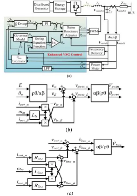
Figure 1. Block diagram of (a) the basic VSG control, (b) the ―Governor Model‖ block and (c) the ―Q Droop‖
block.
By and by, output voltage is still controlled in a roundabout way by the V–Q droop controller and the PI controller of reactive power. With a specific end goal to reduce the impact from ripples in measured output control, a 20Hz first order low-pass filter is connected for as appeared in Figure 1(a). As the
output current is measured after the LC channel organize, the reactive power expended by the LC filter is excluded in . Along these lines, no particular
inertial process is required for the reactive power PI controller. In a microgrid, with a specific end goal to share the active and reactive power as indicated by the evaluations of DGs without correspondence,
( ) ⁄ , ( ) ⁄ ,
⁄ and ⁄ ought to be designed
similarly for every DG in default [2]. In this paper, to disentangle the elucidation for the instance of various power evaluations, per unit qualities are computed in light of particular power evaluations of DGs.
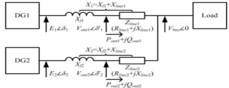
Figure 2. Structure of a microgrid in islanded mode.
III.
ANALYSES OF TRANSIENT ACTIVE POWER PERFORMANCEClosed-Loop State-Space Model
IV.
IMPROVEMENT OF REACTIVE POWER SHARINGFigure 5 demonstrates the standards of ω–P and V–Q droop controls in the "Representative Model" and "Q Droop" pieces appeared in Figure 1 for the instance of Sbase1: Sbase2 = 2 : 1. As examined in Section II, , , and are composed similarly. Based on the predefined linear droop characteristic, the wanted power sharing Pin1: Pin2 = 2 : 1 can be gotten because the governor input is, and is
guaranteed in steady state.
Taking after a similar rule, to share the reactive power as per the power rating proportion, an equivalent voltage reference is required. Be that as it may, for the V–Q droop in essential VSG control appeared in Figure 1(c), the voltage reference is the inverter output voltage, which might be an alternate an incentive for every DG even in steady state because of the line voltage drop. As a large portion of past studies depend on Q–V droop, in which the output voltage . Ought to be controlled in light of
measured responsive power ., the fundamental
thought to deliver this issue is to level . By
balancing the output impedance, or to adjust the line voltage drop. Both techniques require awesome exertion in configuration process and complex calculations in DG control law, though the came about reactive power sharing is still affected by active power sharing.
As the voltage does not require to be controlled straightforwardly in a V–Q droop control plot appeared in Figure 1(a), the reference voltage can be picked other than inverter output voltage. On the off chance that the normal ac bus voltage ., utilized
rather than inverter output voltage ., measure up
to reactive power reference esteem Qref 1 = Qref 2 can be ensured, as it is delineated in Figure 3.
Figure 3. Principles of ω–P and V–Q droop control.
In this manner, exact reactive power sharing Qout1 = Qout2 ought to be gotten through the utilizing of reactive power PI controller. Also, not at all like output voltage, bus voltage is not impacted by line voltage drop, which is dictated by both active and reactive power. In this manner, reactive power sharing as per the bus voltage is autonomous from active power. Direct bus voltage estimation is proposed. In any case, in the field applications, it is hard to gauge . specifically, as DGs may be
introduced far from the normal ac bus, and the use of correspondence is not favored for dependability reason.
Figure 4. Block diagram of (a) the proposed enhanced VSG control, (b) the ―Stator Reactance Adjuster‖ block
V.
PROPOSED ENHANCED VSG CONTROL SCHEMEThe proposed improved VSG control plan is appeared in Figure 4. Contrasted with the essential VSG control, two noteworthy changes are made, i.e., the stator reactance adjuster and the bus voltage estimator, as appeared in Figs. 4(b) and 4(c), individually. The capacity of stator reactance adjuster is to change the output reactance of the DG freely.It is working as a virtual impedance controller. The virtual stator inductor is figured it out by increasing output current by the virtual stator inductor in stationary casing. It will be more exactness if inductor current through is utilized. Be that as it may, this builds the quantity of current sensors, which is redundant. As the current flowing into at fundamental frequency is not as much as few percent of the inductor current, utilizing output current rather than inductor current does not influence the execution of the control plot. Tuning of virtual stator inductor is recommended
to set aggregate output reactance for both DGs in same substantial per unit esteem. The objective esteem is proposed to be 0.7 pu since it is a run of the mill an incentive for the add up to direct-axis transient reactance of a genuine SG.
( )
(11)
The and are considered
as known parameters in this paper. As the size of microgrid is for the most part little, the line distance is effortlessly to be measured or encouraged by the organizer. Regardless of the possibility that it is not the situation, a few online estimation then again keen tuning strategies for Zline.
With the proposed outline of stator reactance alteration, oscillation in a VSG-control-based microgrid ought to be practically dispensed with amid a loading transition in islanded mode. Especially, transition from grid- associated mode to islanded
mode can likewise be considered as a loading transition; along these lines, the oscillation during an islanding occasion ought to likewise be disposed of with the proposed control system, as it is demonstrated by simulation results next area.
The rule of bus voltage estimator in Figure 4(c) is comparable to that of stator reactance adjuster in Figure 4(b). By ascertaining the line voltage drop in stationary casing utilizing measured output current and line impedance information, the bus voltage can be assessed from the distinction of output voltage furthermore, computed line voltage drop. Since the as it is examined in last segment, precise reactive power sharing can be acquired by utilizing evaluated bus voltages as the input references of "Q Droop" rather than particular output voltages of DGs.
Be that as it may, if there is an estimation mistake in ̂ , it will bring about a reactive power sharing
error. Assuming ̂ ̂ and ̂ ̂ ,
( ̂ ̂ ) (12)
That is to state, the reactive power sharing mistake brought on by estimation mistakes is dictated by the V–Q droop gain . The outline of is an outstanding exchange off between voltage deviation and reactive power control exactness. Considering the plausible ripples in the deliberate RMS estimation of ̂ , is
Figure 5. Small-signal model of reactive power control loop.
VI.
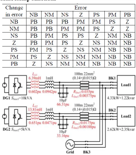
FUZZY LOGIC CONTROLLERThe three variables of the FLC, the error, the change in error and the output, have seven triangle membership functions for each. The basic fuzzy sets of membership functions for the variables are as shown in the Figs.8. The fuzzy variables are expressed by linguistic variables „positive big (PB)‟, ― positive medium(PM)‟, „positive small (PS)‟, „zero (Z)‟, „negative small (NS)‟, ‟, „negative big (NB)‟, ―negative medium(NM)‖ for all three variables. A rule in the rule base can be expressed in the form: If (e is NB) and (de is NB), then (cd is PB). The rules are set based upon the knowledge of the system and the working of the system. The rule base adjusts the duty cycle for the PWM of the inverter according to the changes in the input of the FLC. The number of rules can be set as desired. The numbers of rules are 49 for the seven membership functions of the error and the change in error (inputs of the FLC).
Figure 5.1. Membership function for error for reactive power
Figure 5.2. Membership function for change in error for reactive power
Figure 5.3. Membership function for voltage
Membership functions
Figure 6. Simulation circuit.
VII.
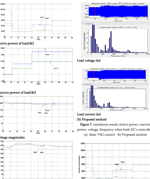
SIMULATION RESULTSare simulated at 21 s, 24 s, and 27 s, individually. The simulation results are appeared in Figure 7.
As it is delineated in Figure 7(a), when the microgrid is islanded at 21 s, and when load 2 is associated at 24 s, oscillation can be seen in active power when the essential VSG control is connected for both DGs. This oscillation is nearly eliminated by applying the proposed improved VSG control appeared in Figure 7(b). As the disturbance at 27 s is brought on by change of active power set estimation of DG1, which is most certainly not a loading transition, active power oscillation can’t be dispensed with for this situation. In any case, the proposed upgraded VSG control expands the damping proportion; accordingly, the overshoots in Figure 7(b) are littler than that in Figure 7(a). In the interim, the oscillation periods turn out to be longer, on the grounds that the damped common frequencies are decreased.
Table.2. Simulation sequence
Time Grid P*01 P*02 Load
t < 21 s connected 1 pu 1 pu Load 1 21 s ≤ t
≤ 24 s
Disconnected - - -
24 s ≤ t ≤ 27 s
- - - Load
1+2 27 s ≤ t
≤ 30 s
- - 0.6 pu -
In addition, on account of the fundamental VSG control, reactive power is not shared appropriately in islanded mode, and is most certainly not controlled at set an incentive in grid- associated mode, because of the voltage drop through the line impedance, as appeared in Figure 7(a). Also, reactive power control is not autonomous from active power control, as a change of set estimation of active power at 27 s additionally causes a change of reactive power sharing. These issues are altogether illuminated in the
upgraded VSG control, as it is appeared in Figure 7(b).
Active powers of load1&2
Reactive powers of load1&2
Voltage magnitudes
Frequencies
Active powers of load1&2
Reactive powers of load1&2
Voltage magnitudes
Frequencies
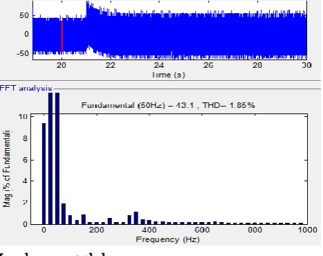
Load voltage thd
Load current thd (b) Proposed method
Figure 7. simulation results Active power, reactive power, voltage, frequency when both DC’s controlled.
(a) Basic VSG control (b) Proposed method
Reactive powers of load1&2
Voltage magnitudes
Frequencies
Load voltage thd
Load current thd
Figure 8. simulation results of active power, reactive power, voltage and frequency when both DGs are
controlled by fuzzy controller
VIII.
CONCLUSION
In this paper, an upgraded VSG control is proposed as a novel correspondence less control technique in a microgrid. A stator reactance adjuster is produced in view of state-space analyses, in order to increase the active power damping and to appropriately share transient active power. A novel communication less reactive power control methodology in view of inversed voltage droop control (V–Q droop control) and regular ac bus voltage estimation is likewise proposed to accomplish exact reactive power sharing, which is resistant to active power sharing change also, line impedance mismatch. Simulation comes about showed that the proposed upgraded VSG control accomplishes desirable transient and steady-state exhibitions, and keeps the inertia support highlight of VSG control. Subsequently, the proposed upgraded VSG control is an ideal decision for the control arrangement of DGs in micro grids.
IX.
REFERENCES
[2]. J. M. Guerrero, J. C. Vasquez, J. Matas, L. G. de Vicuña, and M. Castilla, "Hierarchical control of droop-controlled AC and DC microgrids— A general approach toward standardization," IEEE Trans. Ind. Electron.,vol. 58, no. 1, pp. 158–172, Jan. 2011.
[3]. A. Bidram and A. Davoudi, "Hierarchical structure of microgrids control system," IEEE Trans. Smart Grid, vol. 3, no. 4, pp. 1963–1976, Dec. 2012.
[4]. M. C. Chandorkar, D. M. Divan, and R. Adapa, "Control of parallel connected inverters in standalone AC supply systems," IEEE Trans. Ind. Appl., vol. 29, no. 1, pp. 136–143, Jan./Feb. 1993. [5]. H. Bevrani, M. Watanabe, and Y. Mitani, Power System Monitoring and Control. Hoboken, NJ, USA: Wiley, 2014.
[6]. J. M. Guerrero, J. Matas, L. G. De Vicuña, M. Castilla, and J. Miret, "Decentralized control for parallel operation of distributed generation inverters using resistive output impedance," IEEE Trans. Ind. Electron., vol. 54, no. 2, pp. 994–1004, Apr. 2007.
[7]. T. L. Vandoorn, B. Meersman, L. Degroote, B. Renders, and L. Vandevelde, "A control strategy for islanded microgrids with DC-link voltage control," IEEE Trans. Power Del., vol. 26, no. 2, pp. 703–713, Apr. 2011.
[8]. T. L. Vandoorn, B. Meersman, J. D. M. De Kooning, and L. Vandevelde, "Analogy between conventional grid control and islanded microgrid control based on a global DC-link voltage droop," IEEE Trans. Power Del., vol. 27, no. 3, pp. 1405–1414, Jul. 2012.
[9]. J. C. Vasquez, J. M. Guerrero, M. Savaghebi, J. Eloy-Garcia, and R. Teodorescu, "Modeling, analysis, and design of stationary-referenceframe droop-controlled parallel three-phase voltage source inverters," IEEE Trans. Ind. Electron., vol. 60, no. 4, pp. 1271–1280, Apr. 2013.
[10]. J. Driesen and K. Visscher "Virtual synchronous generators," in Proc. IEEE Power Energy Soc. Gen. Meeting—Convers. Del. Elect. Energy 21st Century, Pittsburgh, PA, USA, 2008, pp. 1–3. [11]. L. M. A. Torres, L. A. C. Lopes, T. L. A. Moran,
and C. J. R. Espinoza, "Self-tuning virtual synchronous machine: A control strategy for energy storage systems to support dynamic frequency control," IEEE Trans. Energy Convers., vol. 29, no. 4, pp. 833–840, Dec. 2014. [12]. Y. Hirase et al., "Virtual synchronous generator
control with double decoupled synchronous reference frame for single-phase inverter," IEEJ J. Ind. Appl., vol. 4, no. 3, pp. 143–151, May 2015.
[13]. K. Sakimoto, Y. Miura, and T. Ise, "Stabilization of a power system with a distributed generator by a virtual synchronous generator function," in Proc. 8th IEEE Int. Conf. Power Electron. ECCE Asia, Shilla Jeju, Korea, 2011, pp. 1498–1505.
G.KRISHNAIAH
currently he is pursuing her Master Degree in the department of Electrical & Electronic Engineering: Quba college of engineering & Technology, venkatachalam, SPAR Nellore dist., Andhra Pradesh, India
Mr. ATCHI RAMBABU