IJSRSET184957 | Received: 12 July 2018 | Accepted: 27 July 2018 | July-August-2018 [ 4 (9): 248-258]
248
Modifying the Structure of a Fuzzy Controller to Improve Speed
Estimation Response in Rotor-Flux MRAS DTC Drive
Yashar Farajpour
Electrical Engineering Department, Science and Research Branch, Islamic Azad University, Tehran, Iran
ABSTRACT
Direct Torque Control (DTC) technique provides a multidimensional control over the target system. From the capability to employ various speed controllers and constant monitoring of the motor state to the minimization of inrush current and voltage sag on the power network side, DTC dictates its excellence evidently. Wide range of functionality along with the fast and precise torque and speed responses have made this system one of the
best choices for the control of an induction motor. However, DTC drive’s inherent need for a rotor speed sensor brings some drawbacks. This paper studies design, calculation, and the performance of a novel Fuzzy scheme implemented in a Model Reference Adaptive System (MRAS) for sensorless speed observation. In order to evaluate the effectiveness of the proposed technique, its results are contrasted with the conventional scheme of a PI controlled MRAS DTC. The operation of a 5hp induction motor is analyzed on MATLAB Simulink platform for various scenarios of abrupt speed demand and load torque changes. Although both MRAS mechanisms demonstrate satisfactory performance in steady state conditions, the Fuzzy based system offers considerably more accurate and reliable responses even for transient states with minimized estimation error and higher signal precision.
Keywords : Direct Torque Control (DTC), Fuzzy logic controller, Motor drives, Model Reference Adaptive System (MRAS), Fuzzy MRAS.
I.
INTRODUCTIONWith the advent of modern induction motors in multifarious applications, the need for advanced motor drives became inescapable. Among the so many control strategies, Direct Torque Control (DTC) technique is one of the most referenced ones. Its functionality in diverse purposes[1], fast response to user demands[2, 3], significant reduction of inrush current and voltage sag in power network[3, 4], capability to control induction motor in demanded low or high speeds[5–8], and resistance against load disturbances[9, 10] are only some of the remarkable advantages of DTC drives. On the other hand, it has some flaws such as switching losses[11] and torque
and flux ripples[2, 12, 13] engendered because of the
inverter’s nature, and other problems related to the use of the speed sensor on the motor’s shaft including the reduction of mechanical robustness of the drive, inappropriateness for hostile work environments (corrosion, moisture, pollution, dust, and etc.), and the
sensor’s high price and high costs of maintenance[11, 14].
International Journal of Scientific Research in Science, Engineering and Technology (www.ijsrset.com)
3
earlier, different alternatives were proposed in thepast [7, 14, 25, 26, 17–24]. Sensorless DTC strategies are generally classified in three categories of Signal Injection[27], State Observer[24], and Model Reference Adaptive System (MRAS)[14, 28] methods. The need for sophisticated calculations and an external signal source weakens the functionality of Signal Injection Method [14, 19]. While State
Observer’s advantage is its simplicity and reliability
against abrupt load changes, it suffers seriously from chattering phenomenon[24, 26]. Eventually, it is MRAS method which is able to satisfy a wide range of demands[7, 14, 23, 29]. Meanwhile, MRAS itself is categorized in four clusters of Back-emf[7], Rotor-Flux[14, 22], Reactive Power[21, 30], and Active Power[29]. This paper is dedicated to study Rotor-Flux strategy, because it balances different desirable factors and satisfies a variety of applications when it is compared with other approaches.
Meanwhile, the advent of Fuzzy sets introduced independently by L.A. Zadeh has changed the concept of mathematics and provided a room for the invention of a variety of novel approaches in different fields[31, 32] and electrical engineering is no exception. Their wide range of application, attractive simplicity, and notable accuracy are the undeniable characteristics of
fuzzy sets. Literally, fuzzy logic works similar human logic; that is why it is simple to design, easy to implement and precise in finding rational solutions. Where an optimum control strategy was a necessity, Fuzzy Logic Controllers (FLCs) were in the focus of attention. Thus, researchers are encouraged to replace the conventional PI Controllers (PICs) with FLCs in sensorless MRAS DTC drives. PICs are common to use in motor drives, while their incapability to cope with sudden load and speed changes are the main disadvantages [14], [18]. Hence, this study is dedicated to investigate the performance of a novel FLC scheme employed as the rotor speed observer in a MRAS system of a DTC drive. The proposed FLC has normalizer gains, gaussian membership functions, and it is designated to adjust the estimated speed value instead of ordering a definitive value in the output. It is assumed here that, because the change in rotor speed is a continuous value, adjusting the estimated value based on the rotor speed of the previous moment can be a better approach. A comprehensive understanding of DTC drive and MRAS speed estimation system is presented in the following, the proposed FLC MRAS technique comes afterwards, and the whole process simulated eventually in order to examine its credibility.
Nomenclature
DTC Direct Torque Control MRAS Model Reference Adaptive System
DSC Direct Self Control PIC Proportional Integral Controller
Ua,b,c Voltage in abc frame FLC Fuzzy Logic Controller
Ud,q,o Voltages in dq frame φds, φqs Stator flux components in dq frame
ia,b,c Currents in abc frame φdr, φqr Rotor flux components in dq frame
id,q,o Currents in dq frame φ̂ , φdr ̂qr Estimated rotor flux components
Te, Te∗ Actual and Reference Electromagnetic torques θφ Stator flux angle
ωn, ω∗ Nominal and Reference rotor speeds φsn Nominal stator flux
ωr, ω̂r Actual and Estimated rotor speeds |φs| Stator flux amplitude
(ξω) Rotor speed tuning error ki, kp Integral and Proportional gains
Rs, Rr Stator and Rotor resistances Ls, Lr, Lm Stator, Rotor, and Mutual inductances
p Motor pole pairs τr Rotor time constant
V0−7 Eight voltage vectors of two-level inverter HT, Hφ Torque and Flux hysteresis commands
VA Apparent power in volt-ampere rpm Revolutions per minute
II.
MATHEMATICAL MODEL OF A
CONVENTIONAL DTC DRIVE
The general scheme of a conventional DTC drive is shown in Figure 1. DTC measures input voltages and currents of the induction motor fed by a 2-level inverter. These measured amplitudes must be transformed from abc to dq frame as expressed below [33]:
𝑈𝑑𝑞𝑜 =
[
1 −12 − 1 2
0 −√3 2
√3 2 1
2 1 2
1 2 ]
[ 𝑈𝑎 𝑈𝑏 𝑈𝑐
] (1)
𝑖𝑑𝑞𝑜 =
[
1 −12 − 1 2
0 −√3 2
√3 2 1
2 1 2
1 2 ]
[ 𝑖𝑎 𝑖𝑏 𝑖𝑐
] (2)
Accordingly, the stator flux on the dq axes (𝜑𝑑𝑠, 𝜑𝑞𝑠) and the electromagnetic torque (𝑇𝑒) can be calculated
by the equations stated in the following:
{𝜑𝑑𝑠= ∫(𝑈𝑑𝑠− 𝑅𝑠𝑖𝑑𝑠) 𝑑𝑡
𝜑𝑞𝑠 = ∫(𝑈𝑞𝑠− 𝑅𝑠𝑖𝑞𝑠) 𝑑𝑡 (3)
{|𝜑𝑠| = √(𝜑𝑑𝑠2 + 𝜑𝑞𝑠2 ) 𝜃𝜑= ∡𝜑̂𝑠
(4)
𝑇𝑒= 3
2𝑝[(𝜑𝑑𝑠𝑖𝑞𝑠) − (𝜑𝑞𝑠𝑖𝑑𝑠)] (5)
where 𝑝 and 𝜃𝜑 represent pole pairs and stator flux position respectively.
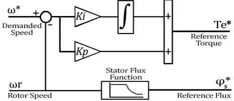
As shown in Figure 2, the reference electromagnetic torque (𝑇𝑒∗) is generated by a PIC which works based on the rotor speed error. It can be expressed by the following equation:
𝑇𝑒∗= 𝑘𝑖∫(𝜔∗− 𝜔𝑟)𝑑𝑡+ 𝑘𝑝(𝜔∗− 𝜔𝑟) (6)
where, 𝑘𝑖 and 𝑘𝑝 are the controllers integral and proportional gains respectively.
Although stator flux must be kept at a constant value for different rotor speeds, it should be reduced for
velocities higher than the motor’s nominal speed.
Since the stator voltage has a constant peak amplitude, the increase in the frequency is the only possible option to achieve higher velocities. Therefore, the reduction of stator flux must be taken into consideration in order to keep motor in constant power region [34, 35]. Eventually, the function of reference stator flux operates based on the rules Figure 1: Schematic illustration of a conventional DTC drive.
Figure 2: Speed controller block of a conventional
International Journal of Scientific Research in Science, Engineering and Technology (www.ijsrset.com)
5
below:𝜑𝑠∗= {
𝜑𝑠𝑛 , 0 < 𝜔𝑟 ≤ 𝜔𝑛 𝜔𝑛×𝜑𝑠𝑛
𝜔𝑟 , 𝜔𝑟 > 𝜔𝑛
(7)
where, 𝜑𝑠∗ is the reference stator flux, 𝜑𝑠𝑛 is the nominal stator flux, 𝜔𝑟 is the actual rotor speed, and 𝜔𝑛 is the nominal rotor speed.
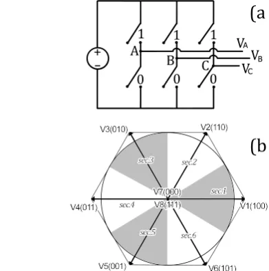
According to Figure 1, the three-level and two-level hysteresis controllers are responsible to evaluate the differences between reference and actual values of electromagnetic torque (𝑇𝑒∗, 𝑇𝑒) and stator flux (𝜑𝑠∗, 𝜑𝑠) in order to generate 𝐻𝑇 and 𝐻𝜑 signals respectively. These signals help DTC to understand motor condition and to adjust torque and flux values in accordance with user demand. The output of the three-level hysteresis controller can be 1, 0, and -1 which indicate that electromagnetic torque should be increased, kept constant, or decreased respectively.
While, the stator flux’s hysteresis controller has two
levels of 0 and 1 to express the need for decrease or increase respectively. Ultimately, the switching table
triggers inverter’s gates according to Table 1 and the
voltage vectors of the two-level inverter shown in Figure 3 [3, 36, 37]. It is noteworthy that, 𝜃𝜑 is categorized into 6 × 60° sectors on the stator flux plane.
III.
ROTOR-FLUX MRAS
As it is shown in Figure 4, MRAS system is consisted of four fundamental sections (Reference Model, Adjustable Model, Error Signal, and Adaptation Mechanism). The Reference Model is responsible to generate stator flux values as expressed in Eq. (3) and to produce reference rotor flux values subsequently according to the equation stated below[22, 29]:
[𝜕𝜑𝜕𝜑𝑑𝑟 𝑞𝑟] =
𝐿𝑟 𝐿𝑚{[
𝜕𝜑𝑑𝑠 𝜕𝜑𝑞𝑠] − [
𝜎𝜕𝐿𝑠 0 0 𝜎𝜕𝐿𝑠] [
𝑖𝑑𝑠
𝑖𝑞𝑠]} (8)
In contrast, the Adjustable Model is dependent on the estimated rotor speed (𝜔̂𝑟) assessed by the Adaptation Mechanism. The Adjustable Model generates adjustable rotor flux values till the rotor speed tuning error (𝜉𝜔) becomes zero. The estimated rotor flux components (𝜑̂𝑑𝑟,𝜑̂𝑞𝑟) and speed tuning error (𝜉𝜔) can be obtained as follows [14]:
[𝜕𝜑𝜕𝜑̂𝑑𝑟 𝑞𝑟 ̂ ]= [
−1 𝜏 𝑟
⁄ −𝜔̂𝑟 −𝜔̂𝑟 −1⁄𝜏𝑟
] [𝜑𝜑̂𝑑𝑟 𝑞𝑟 ̂ ]+
𝐿𝑚 𝜏𝑟[
𝑖𝑑𝑠
𝑖𝑞𝑠] (9)
𝜉𝜔= (𝜑̂ × 𝜑𝑑𝑟 𝑞𝑟) − (𝜑̂ × 𝜑𝑞𝑟 𝑑𝑟) (10)
Table 1. Switching Table of a Conventional DTC Drive.
θφ sector 1 2 3 4 5 6
Hφ= +1
HT = +1 V2 V3 V4 V5 V6 V1 HT = 0 V7 V0 V7 V0 V7 V0 HT = -1 V6 V1 V2 V3 V4 V5
Hφ= -1
HT = +1 V3 V4 V5 V6 V1 V2 HT = 0 V0 V7 V0 V7 V0 V7 HT = -1 V5 V6 V1 V2 V3 V4 Figure 3: Schematic representation of a three-level
inverter (a) and its voltage vectors on stator flux plane (b).
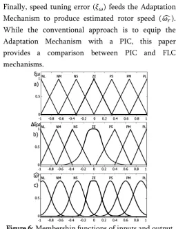
Finally, speed tuning error (𝜉𝜔) feeds the Adaptation Mechanism to produce estimated rotor speed (𝜔̂𝑟). While the conventional approach is to equip the Adaptation Mechanism with a PIC, this paper provides a comparison between PIC and FLC mechanisms.
A.PI and Fuzzy MRAS Control Strategies
Nowadays, PI controllers are ubiquitous in a variety of applications. However, in this specific case, a PI controller suffers from some disadvantages such as inability to cope with sudden load and speed disturbances, complex mathematical modelling, and the need for gain tuning. Thus, it is inevitable to move towards more flexible methods such as FLCs. The high adaptability and less mathematical complexity of FLCs make them a felicitous choice for sensorless DTC drives[14, 18, 22, 25, 38, 39].
This paper presents a Mamdani FLC which its diagrammatic model and membership functions are depicted in Figure 5 and Figure 6 respectively. While the inputs are speed tuning error (𝜉𝜔) and its rate of change (∆𝜉𝜔) as expressed in Eq. (11), the output is the estimated rotor speed (𝜔̂𝑟). In this paper, different shapes of membership functions are defined in order to achieve smoother results, especially for steady state conditions. It should be mentioned that all of the values are normalized between -1 and +1 by two gains (𝐾𝜉,𝐾𝛥𝜉) in the inputs and another (𝐾𝜔𝑟̂) in the output of the FLC as shown in Figure 5. Furthermore, the FLC rule base is presented in Table 2 as proposed by [14]. Where, membership functions are defined as Negative Large (NL), Negative Medium (NM), Negative Small (NS), Zero (ZE), Positive Small (PS), Positive Medium (PM), Positive Large (PL).
∆𝜉𝜔(𝑡)= 𝜉𝜔(𝑡)− 𝜉𝜔(𝑡−1) (11)
IV.
SIMULATION RESULTS
Series of comprehensive simulations are performed on an asynchronous 5hp 3-phase squirrel-cage induction motor equipped with the two MRAS DTC models discussed above in MATLAB/Simulink environment to analyze the performance of each strategies side by side. The electrical and mechanical parameters of the induction motor are presented in Table 3. The results
are obtained under the sampling time of 20μ seconds.
To assess the accuracy and efficiency of each system, Figure 5: Schematic illustration of the proposed FLC
for MRAS.
Figure 6: Membership functions of inputs and output of the proposed FLC: (a) speed tuning error, (b) changes
in speed tuning error, and (c) estimated rotor speed.
Table 2. Rules of the Proposed FLC for MRAS System.
∆ξω
ξω NL NM NS ZE PS PM PL
NL NL NL NL NM NS NS ZE
NM NL NL NM NM NS ZE PS
NS NL NM NS NS ZE PS PM
ZE NL NM NS ZE PS PM PL
PS NM NS ZE PS PS PM PL
PM NS ZE PS PM PM PL PL
International Journal of Scientific Research in Science, Engineering and Technology (www.ijsrset.com)
7
the actual rotor speed is also measured with a speedsensor.
A.No-load Condition
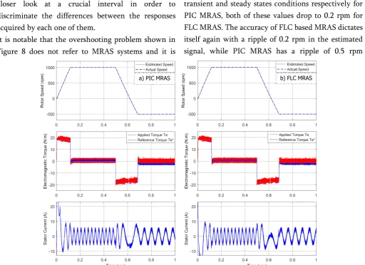
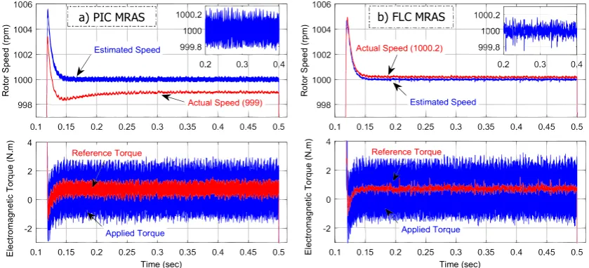
Firstly, both of the drives have started to work with the speed demand of 1500 rpm under no-load condition. At time 0.5 seconds, the speed command of -500 rpm in reverse motoring is ordered to the drives. Figure 7 depicts actual and estimated rotor speeds (a), applied by inverter and reference electromagnetic torques (b), and stator currents (b) for PIC and FLC based MRAS DTC approaches. Both of the drives started with the reference electromagnetic torque of 18 N.m and it has taken only 0.12 seconds for each one of them to reach to the speed demand of 1000 rpm. At the first glance, the performances of the two strategies seem quite similar, while Figure 8 provides a closer look at a crucial interval in order to discriminate the differences between the responses acquired by each one of them.
It is notable that the overshooting problem shown in Figure 8 does not refer to MRAS systems and it is
because of the performance of the PI speed controller expressed earlier which is not the aim of this study to investigate. While the difference between the estimated and actual rotor speed is 3 and 1 rpm in transient and steady states conditions respectively for PIC MRAS, both of these values drop to 0.2 rpm for FLC MRAS. The accuracy of FLC based MRAS dictates itself again with a ripple of 0.2 rpm in the estimated signal, while PIC MRAS has a ripple of 0.5 rpm
Figure 7: Performance of PIC (a) and FLC (b) based MRAS sensorless DTC drives under no-load condition.
Table 3. The Parameters of the Simulated Induction Motor.
Parameters Values
Nominal power 5 hp / 3730 VA
Voltage (rms), Frequency 460 V, 60 Hz Stator resistance (Rs) 1.115 Ω
Stator inductance (Ls) 5.974 mH Rotor resistance (Rr) 1.083 Ω
Rotor inductance (Lr) 5.974 mH Mutual inductance (Lm) 203.7 mH
Pole pairs (p) 2 pairs
Inertia (J) 0.02 Kg.m2
around the target signal. This uncertainty forces the speed control block to constantly change its reference torque command in a futile effort to keep rotor speed on the demanded value. The more preferable performance of FLC MRAS with narrower reference torque signal in contrast of thicker signal of PIC MRAS is conspicuous in Figure 8. A similar scenario happens again for the speed command of -500 rpm.
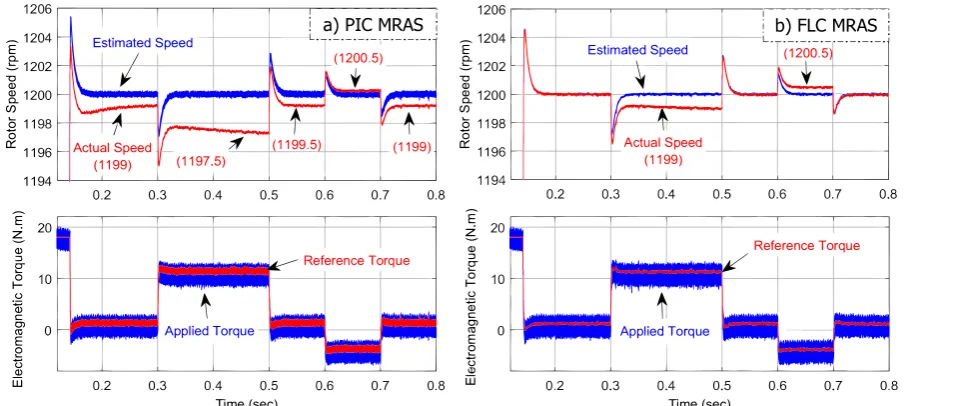
B. Load Torque Condition
Figure 9 depicts the performance of the discussed drive strategies under load-torque disturbances in the constant speed of 1200 rpm. A heavy step load of 10 N.m is applied to the shaft in the interval of 0.3 until 0.5 seconds, load is removed, and then rotor is coupled with a reverse load of -5 N.m between 0.6 till 0.7 seconds. Despite the trivial steady state error, the performance of PIC MRAS is satisfactory generally. However, its functionality under sudden load torque changes is quite unreliable. Although it has a steady state error of 1 rpm, this amplitude drops further to 2.5 rpm when the 10 N.m load is applied on the rotor. On the other hand, FLC MRAS has an insignificant error of 0.2 rpm in steady state conditions and it is increased only to 1 rpm in the most challenging situation of handling a 10 N.m load. In addition, its accuracy of estimation even in overshooting periods is compelling. When the load is detached, the PIC has a
0.5 rpm underestimation problem, while the FLC follows actual rotor speed precisely in the interval of 0.5 till 0.6 seconds. Once the -5 N.m load torque is applied, the underestimation problem of the PIC helps it to tie with the FLC with an error of 0.5 rpm. As mentioned earlier, the precise reference toque signal for FLC MRAS as illustrated in Figure 9 is obtained because of less ripple and minimum error in speed estimation. The thickness of the reference electromagnetic signal is not desirable, because it is an indication of uncertainty of speed control system. This uncertainty, in this case, is caused by the ripple in the estimated speed signal which feeds the speed control block.
According to Figure 8 and Figure 9, it is notable that in contrast to what was presented before by [14], there is not any significant difference between the applied torque ripple of PIC MRAS and FLC MRAS. Both of the controllers have a ripple of 4 N.m in the applied electromagnetic torque, because their hysteresis bands are set on 4 N.m. Surprisingly, the results of Ramesh et al. suggest that with the application of FLC in MRAS system not only speed estimation response will be improved, but also the ripple of applied torque will significantly decrease. Although it is in the nature of DTC to have ripples in the torque signal due to the switching of the inverter, Figure 8: A closer look to the performance of PIC (a) and FLC (b) based MRAS DTC drives between 0.1 and 0.5
International Journal of Scientific Research in Science, Engineering and Technology (www.ijsrset.com)
9
there are only two possible solutions to minimize itsripple. The first approach is to reduce the sampling time of the system; it provides more information and grants faster responses. However, it increases switching frequency that engenders more harmonic and switching losses consequently. The second and more preferable approach is to replace the conventional two-level inverter with a three-level inverter which brings 21 voltage vectors in three different amplitudes; however, it requires an optimum switching table. Triggering of smaller voltage vectors to compensate smaller errors of torque signal results in significantly less ripple. Unless considering the mentioned approaches, it is unlikely to reduce torque ripple in DTC drives. Unfortunately, [14] offers no explanation regarding the link between torque ripple reduction and FLC MRAS strategy.
V.
CONCLUSION
This study attempted to provide a comprehensive understanding of sensorless DTC drives and to introduce a novel scheme for the implementation of FLC in MRAS system. The theoretical principles presented earlier aimed at facilitating the comprehension of DTC and MRAS concepts. The alternative scheme for FLC MRAS exhibited here was
structured to estimate rotor speed by adjusting it based on the error between the reference and the estimated rotor fluxes and its rate of change. The presented PIC and FLC based MRAS DTC drives were simulated under the exactly similar conditions. Under no-load condition, the PIC MRAS has shown that it is able to provide a satisfactory performance, despite a steady error of 1 rpm and a ripple of 0.5 rpm in the estimated rotor speed. On the other hand, the output of FLC MRAS followed actual rotor speed precisely even in the most challenging transient conditions; it has estimated the rotor speed with an insignificant error of 0.2 rpm. Under load torque disturbances, the FLC MRAS asserted its distinction once again with minimum speed drop in full-load periods and almost zero error in no-load conditions. Additionally, the accuracy of the proposed FLC MRAS in the estimation
of rotor speed assisted DTC’s speed controller to
produce reference torque signal with more certainty. Simulations carried out in MATLAB/Simulink software confirms the validity of the proposed FLC MRAS strategy for various functions. However, further studies can develop this method and improve its performance through devising a new rule table for the employed fuzzy controller or investigating the effectiveness of the implementation of a Type-2 fuzzy controller to overcome current drawbacks.
VI.
REFERENCES
[1]. P. Vas, Sensorless vector and direct torque control. Oxford University Press, 1998.
[2]. Y. Cho, Y. Bak, and K.-B. Lee, "Torque-Ripple Reduction and Fast Torque Response Strategy for Predictive Torque Control of Induction Motors,"IEEE Trans. Power Electron., vol. 33, no. 3, pp. 2458–2470, Mar. 2018.
[3]. I. Takahashi and T. Noguchi, "A New Quick-Response and High-Efficiency Control Strategy of an Induction Motor,"IEEE Trans. Ind. Appl., vol. IA-22, no. 5, pp. 820–827, Sep. 1986.
[4]. I. Takahashi and T. Noguchi, "Quick Torque Response Control of an Induction Motor Based on a New Concept,"IEEJ, pp. 61–70, 1984.
[5]. Y. Tatte, M. V. Aware, J. K. Pandit, and R. Nemade, "Performance Improvement of Three-Level Five-Phase Inverter Fed DTC Controlled Five-Five-Phase Induction Motor during Low-Speed Operation,"IEEE Trans. Ind. Appl., pp. 1–1, 2018.
[6]. S. Payami and R. K. Behera, "An Improved DTC Technique for Low-Speed Operation of a Five-Phase Induction Motor,"IEEE Trans. Ind. Electron., vol. 64, no. 5, pp. 3513–3523, May 2017.
[7]. M. Rashed and A. F. Stronach, "A stable back-EMF MRAS-based sensorless low-speed induction motor drive insensitive to stator resistance variation,"IEE Proc. - Electr. Power Appl., vol. 151, no. 6, p. 685, 2004.
[8]. A. Shinohara, Y. Inoue, S. Morimoto, and M. Sanada, "Asymptotic MTPF control for high-speed operations in direct torque controlled IPMSM drives,"in 2017 IEEE 12th International Conference on Power Electronics and Drive Systems (PEDS), 2017, pp. 816–821.
[9]. B. L. G. Costa, C. L. Graciola, B. A. Angélico, A. Goedtel, and M. F. Castoldi, "Metaheuristics optimization applied to PI controllers tuning of a DTC-SVM drive for three-phase induction motors,"Appl. Soft Comput., vol. 62, pp. 776–788, Jan. 2018.
[10]. X. Mei, X. Lu, A. Davari, E. A. Jarchlo, F. Wang, and R. Kennel, "Torque disturbance observer based model predictive control for electric drives,"in 2018 9th
Annual Power Electronics, Drives Systems and Technologies Conference (PEDSTC), 2018, pp. 499– 504.
[11]. S. Karpe, S. A. Deokar, and A. M. Dixit, "Switching losses minimization by using direct torque control of induction motor,"J. Electr. Syst. Inf. Technol., vol. 4, no. 1, pp. 225–242, May 2017.
[12]. C. Xiong, H. Xu, C. Fang, and H. Zhang, "Direct torque control of permanent-magnet synchronous machine drives with reduced torque ripple and strong robustness,"in 2017 IEEE Transportation Electrification Conference and Expo, Asia-Pacific (ITEC Asia-Pacific), 2017, pp. 1–6.
[13]. T. Yuan et al., "Duty Ratio Modulation Strategy to Minimize Torque and Flux Linkage Ripples in IPMSM DTC Systems,"IEEE Access, vol. 5, pp. 14323–14332, 2017.
[14]. T. Ramesh, A. Kumar Panda, and S. Shiva Kumar, "Type-2 fuzzy logic control based MRAS speed estimator for speed sensorless direct torque and flux control of an induction motor drive,"ISA Trans., vol. 57, pp. 262–275, Jul. 2015.
[15]. M. Depenbrock, "Direct self-control of the flux and rotary moment of a rotary-field machine,"US4678248 A, 1984.
[16]. M. Depenbrock, "Method and Device for Controlling of a Rotating Field Machine,"DE3438504 (A1), 1986. [17]. C. Lascu, I. Boldea, and F. Blaabjerg, "A modified
direct torque control for induction motor sensorless drive,"IEEE Trans. Ind. Appl., vol. 36, no. 1, pp. 122– 130, 2000.
[18]. H. Li, A. Monti, and F. Ponci, "A Fuzzy-Based Sensor Validation Strategy for AC Motor Drives,"IEEE Trans. Ind. Informatics, vol. 8, no. 4, pp. 839–848, Nov. 2012.
[19]. J. Holtz, "Sensorless Control of Induction Machines—With or Without Signal Injection,"IEEE Trans. Ind. Electron., vol. 53, no. 1, pp. 7–30, Feb. 2006.
[20]. J. Faiz, M. B. B. Sharifian, A. Keyhani, and A. B. Proca, "Sensorless direct torque control of induction motors used in electric vehicle,"IEEE Trans. Energy Convers., vol. 18, no. 1, pp. 1–10, Mar. 2003.
International Journal of Scientific Research in Science, Engineering and Technology (www.ijsrset.com)
11
Motor Drive,"Iran. J. Electr. Electron. Eng., vol. 10, no. 4, pp. 304–313, 2014.
[22]. S. M. Gadoue, D. Giaouris, and J. W. Finch, "MRAS Sensorless Vector Control of an Induction Motor Using New Sliding-Mode and Fuzzy-Logic Adaptation Mechanisms,"IEEE Trans. Energy Convers., vol. 25, no. 2, pp. 394–402, Jun. 2010. [23]. M. F. Iacchetti, M. S. Carmeli, F. Castelli Dezza, and
R. Perini, "A speed sensorless control based on a MRAS applied to a double fed induction machine drive,"Electr. Eng., vol. 91, no. 6, pp. 337–345, Jan. 2010.
[24]. C.-L. Chen and C.-M. Lee, "Observer-based speed estimation method for sensorless vector control of induction motors,"IEE Proc. - Control Theory Appl., vol. 145, no. 3, pp. 359–363, May 1998.
[25]. Y.-C. Luo and W.-X. Chen, "Sensorless stator field orientation controlled induction motor drive with a fuzzy speed controller,"Comput. Math. with Appl., vol. 64, no. 5, pp. 1206–1216, Sep. 2012.
[26]. J. Maes and J. A. Melkebeek, "Speed-sensorless direct torque control of induction motors using an adaptive flux observer,"IEEE Trans. Ind. Appl., vol. 36, no. 3, pp. 778–785, 2000.
[27]. A. Yousefi-Talouki, P. Pescetto, G. Pellegrino, and I. Boldea, "Combined Active Flux and High-Frequency Injection Methods for Sensorless Direct-Flux Vector Control of Synchronous Reluctance Machines,"IEEE Trans. Power Electron., vol. 33, no. 3, pp. 2447–2457, Mar. 2018.
[28]. A. Mastanaiah and T. Ramesh, "Rotor-flux based MRAS speed estimator for direct torque and flux control of an induction motor drive,"in 2015 IEEE Students Conference on Engineering and Systems (SCES), 2015, pp. 1–6.
[29]. H. Madadi Kojabadi, "Active power and MRAS based rotor resistance identification of an IM drive,"Simul. Model. Pract. Theory, vol. 17, no. 2, pp. 376–389, Feb. 2009.
[30]. S. Maiti, C. Chakraborty, Y. Hori, and M. C. Ta, "Model Reference Adaptive Controller-Based Rotor Resistance and Speed Estimation Techniques for Vector Controlled Induction Motor Drive Utilizing Reactive Power,"IEEE Trans. Ind. Electron., vol. 55, no. 2, pp. 594–601, 2008.
[31]. L. A. Zadeh, "Fuzzy sets,"Inf. Control, vol. 8, no. 3, pp. 338–353, Jun. 1965.
[32]. L. A. Zadeh, "The concept of a linguistic variable and its application to approximate reasoning—I,"Inf. Sci. (Ny)., vol. 8, no. 3, pp. 199–249, Jan. 1975.
[33]. W. C. Duesterhoeft, M. W. Schulz, and E. Clarke, "Determination of Instantaneous Currents and Voltages by Means of Alpha, Beta, and Zero Components,"Trans. Am. Inst. Electr. Eng., vol. 70, no. 2, pp. 1248–1255, Jul. 1951.
[34]. S. K. Pillai, Analysis Of Thyristor Power-Conditioned Motors. Universities Press (India) Pvt. Limited, 1993. [35]. B. M. Wilamowski and J. D. Irwin, Power Electronics
and Motor Drives, Illustrate. CRC Press, 2016. [36]. M. A. Perales, M. M. Prats, R. Portillo, J. L. Mora, J. I.
Leon, and L. G. Franquelo, "Three-dimensional space vector modulation in abc coordinates for four-leg voltage source converters,"IEEE Power Electron. Lett., vol. 1, no. 4, pp. 104–109, Dec. 2003.
[37]. R. Zhang, V. H. Prasad, D. Boroyevich, and F. C. Lee, "Three-dimensional space vector modulation for four-leg voltage-source converters,"IEEE Trans. Power Electron., vol. 17, no. 3, pp. 314–326, May 2002.
[38]. N. Bounar, A. Boulkroune, F. Boudjema, M. M׳Saad, and M. Farza, "Adaptive fuzzy vector control for a doubly-fed induction motor,"Neurocomputing, vol. 151, pp. 756–769, Mar. 2015.
[39]. N. Bounar, A. Boulkroune, and F. Boudjema,