www.ijaera.org 77
FPGA Implementation of Low Power Image
Scaling using Area and Fuzzy Algorithm
K. Malarvizhi1, Dr. R. Nagarajan 2*
1
P.G. Scholar, Department of ECE, Raja College of Engineering & Technology, Madurai,
Tamil Nadu, INDIA, E-mail: [email protected]
2
Professor & Head, Department of ECE, Raja College of Engineering & Technology, Madurai,
Tamil Nadu, INDIA, *E-mail: [email protected]
Abstract: Interpolation is one of the widely used in many applications Image processing such as scaling, re-sampling and re-targeting. The Interpolation which estimates unknown target pixel value from surrounding neighborhood known pixels, the quality of Interpolation algorithm depends on number of pixels used in estimation. An image consists of edge and smooth pixels. Hence To exploiting content of the image, we propose model hybrid model for interpolation techniques to reduce cost and increase speed and as well as reduce noise appearance. The hybrid model estimation pixel value from two kind of algorithm, they fuzzy gradient interpolation for edge pixels and area interpolation for smooth pixels.
Keywords:Index; FPGA; Interpolation; Low power; Image scaling
I. INTRODUCTION
In digital image scaling, image interpolation algorithms are used to convert an image from one resolution to another resolution without losing the visual content in the image [1]. In the color, image interpolation is the process of estimating the missing colour samples to reconstruct a full color image. Image scaling is widely used in many fields, ranging from consumer electronics, such as digital camera, mobile phone, tablet, display devices and medical imaging like computer assisted surgery (CAS) and digital radiographs. In many applications, from consumer electronics to medical imaging, it is desirable to improve the restructured image quality and processing performance of hardware implementation.
In this technological endeavor several interpolation techniques have been developed ranging from very simple to highly complex techniques. Image interpolation becomes the preprocessing step for other image processing tasks like image registrations, image rotation. Image registration needs interpolation to accurately register the image at sub-pixel level.
Image up scaling methods are implemented for a variety of computer equipment’s like printers, digital television, media players, image processing systems, graphics renderers, and so on. On the other hand, high resolution image may need to be scaled down to a small size in order to fit the lower resolution of small liquid crystal display panels. That is, the image scaling is a challenging and very significant issue in digital image processing.
II. RELATED WORK
www.ijaera.org 78
desired location. In other words interpolation reconstructs thepixel values that are lost in sampling by smoothing with an interpolation function.
a) Win scale Image Interpolation
Image scaling using winscale [2] is proposed by Kim et al. The scaling algorithm is to improve the quality and to reduce the computational complexity by reducing number of operations per pixel. This algorithm can perform both scale up and scale down transform using an area pixel model rather than a point pixel model. To provide low complexity, it uses a maximum of four pixels of an original image to calculate one pixel of a scaled image. Also, it can provide better quality by the characteristics such as fine-edge and changeable smoothness.
The hardware of winscale is implemented using an FPGA for displaying scenes in a liquid crystal display panel. Winscale has good scale property with low complexity. Further, this work tells that the winscale algorithm has low RMSE and it has better image quality than the bilinear algorithm. This implementation utilizes 29000 gates at operating frequency of 65MHz.
b) VLSI Design of Winscale for Digital Image Scaling
Lin et al. proposed a VLSI design of winscale algorithm [3] for digital image scaling. This winscale technique uses an area pixels model to evaluate a scaled pixel. The original image and the scaled image are treated as rectangular and the intensity pixel is evenly scattered in rectangular area. The scaled image could be obtained by source image with scaling up/down in various ratios. The scale ratio that comprises horizontal scale ratio (HSR) and vertical scale ratio (VSR) is greater than 1.0 for scale up and less than 1.0 for scale down.
The VLSI architecture of this scaling algorithm is implemented by UMC 0.18 𝜇m CMOS
standard cell library. The total gate count is 17414 with the operating frequency of 130.24MHz. This
architecture occupies 450 × 450 𝜇m2 core area of chip and total power consumption is 19.41mW.
Further, this can be used for processing image interpolation for high definition television (HDTV) in real time.
c) Real-Time FPGA Linear Convolution Interpolation
A linear interpolation is [4] presented by Lin et al., which is low-cost hardware architecture with digital image scaling for real-time requirements. The scheme has the advantage of low operation complexity which reduces the coefficient generating effort and hardware cost with the interpolation quality, compatible to that of bi-cubic convolution interpolation.
The operation of linear convolution interpolation requires 16 weighting coefficients, generated from 16 neighboring pixels of source image. Therefore, the number of adders and subtractions used to generate weighting coefficients in this method are much less than the bi-cubic algorithm. The hardware architecture of this algorithm is implemented on Virtex-II FPGA. But the winscale and bi-cubic achieve lower PSNR as 28.1 and 33.05, respectively for the 3/2 upscaling image after 2/3 downscaling.
III. PROPOSED SCALING
www.ijaera.org 79
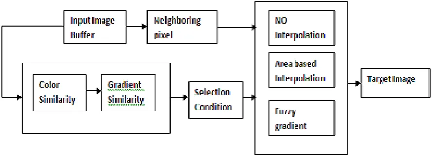
foreground object inner pixels have similar properties. But boundary separating objects from background has more dissimilarity pixels. Our proposed system use two different of interpolation techniques to carried out interpolation on image based on pixel similarity of neighboring pixels in the image.
Fig. 1: Block diagram of proposed Image scaling
In state-of-the-art low-cost VLSI implementations for 2-D signal interpolation, performances such as circuit area in terms of number of configurable logic blocks (CLBs in field-programmable gate array (FPGA) implementation) or gate count and processing frequency in terms of pixel rate are of primary concern.
A. Neighboring Pixel Similarity and Dissimilarity
An unknown pixel is estimated from known 16 neighboring pixels. The neighboring read from buffer and the similarity and dissimilarity measurement is carried out among the 16 neighboring pixels. If the pixel similarity is greater than a threshold value, the estimating known pixel is in the coarse region otherwise the pixel in fine region or neighboring pixel’s average value is equal to unknown pixel value [6].
Two type of interpolation techniques are carried out interpolation based on pixel intensity similarities. If estimating an unknown pixel of smooth or fine is estimated by nearest neighboring interpolation and estimation unknown pixel value of coarse region or boundary of object is carried out by fuzzy gradient interpolation.
B. Iterative I-D Linear Interpolation
In the 1-D case, we use fuzzy logic concept to estimate linearly the impact of neighbor pixels on the gradient of the target pixel. Then, we apply linear approximation again to estimate the target pixel and derived the interpolation polynomial [7].
The 1-D ILI estimates target point Px according to four sample points P1, P2, P3, and P4, as shown in Fig. 2. The distances among sample points P1 to P4 are fuzzified with fuzzy sets characterized by membership functions as shown in Fig. 3, where x1 to x4 are the x-axis coordinates
of P1 to P4, respectively. In figures, 2 and 3, x is the coordinate of the target point Px and x ∈ [x2,
www.ijaera.org 80 Fig. 2: Fuzzy Gradient Neighbor Pixel Selection
q12 = f (x2) – f ( x1)
____________ (1) x2– x1
q12 = f (x3) – f ( x2)
________________ (2) x3– x2
q12 = f (x4) – f ( x3)
________________ (3) x4– x3
The gradient impacts qL and qR estimated on the left and right sides of Px are as. The impacts of sample points on the target point are related here using TS inference. For physical meaning in, the known gradients q12 and q23 have impacts on gradient of Px from the left side while q23 and q34 have impacts on gradient of Px from the right side. Both denominators in equal 1 if the fuzzy sets adopt triangular membership functions. Therefore, computation of requires two adders and four multipliers both in uniform and non-uniform sampling cases. Moreover, we see that gradient impacts qL and qR are linear combinations of q12, q23, and q34 if the fuzzy sets L1, R1, L2, and R2 adopt triangular membership functions.
www.ijaera.org 81 C. 2-D ILI based on multiple 1-D ILI
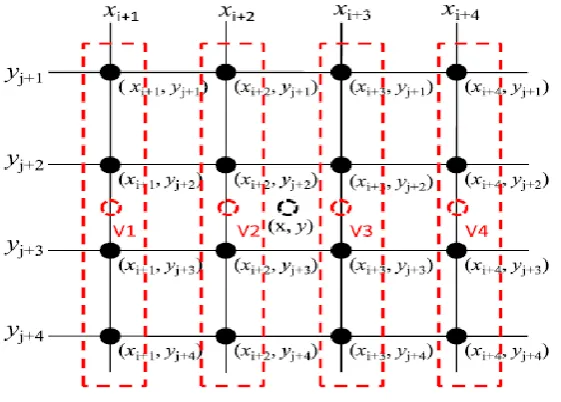
The 2-D ILI comprises multiple 1-D ILI interpolations. Suppose we are estimating the target at (x, y) as shown in figure 3, where 16 sample points (xi+k , yi+k ), k = 1, 2, 3, 4 are given and xi+2 < x < xi+3, y j+2< y < yj+3. First, four virtual points Vks are estimated using 1-D ILI interpolations in the respective vertical directions. The dashed boxes indicate that the virtual points are obtained by performing vertical 1-D ILI at verticals xi+1 to xi+4, respectively [8].
Figure 3: Proposed 2D Image Scaling
At each vertical xi+k , the sample points (xi+k , y j+1), (xi+k , y j+2), (xi+k , yj+3), and (xi+k , yj+4) serve as inputs of 1-D ILI to produce Vk . Then, using these four virtual points Vks on the same horizon, additional 1-D ILI interpolation give the estimation of the target point at (x, y).
D. Color pixel Similarity
The similarity measurement is carried among neighboring pixels, in order to select appropriate interpolation techniques to reduce computation cost. The Manhattan distance metric used here for intensity similarity measurements. Each pixel has vector of color component (red, green and blue) intensity value. The Manhattan distance function computes the distance that would be traveled to get from one data point to the other if a grid-like path is followed [9]. The Manhattan distance between two items is the sum of the differences of their corresponding components. The formula for this distance between a pixel X and Y, X=(X1, X2, X3) and a point Y= (Y1, Y2, Y3) is:
E. Area based Interpolation
www.ijaera.org 82 Figure 4: Number of source pixels overlapped by the current target pixel window
Let the luminance values of four source pixels overlapped by the window of current target pixel at coordinate be denoted as FS(m,n), FS(m+1,n), FS(m,n+1), and FS(m+1,n+1) respectively.
The estimated value of current target pixel, denoted as can be calculated by weighted averaging the luminance values of four source pixels with area coverage ratio as:
F(K,L)=f(m,n) w(m,n)+f(m+1,n) w(m+1,n)+f(m,n+1) w(m,n+1)+f(m+1,n+1) w(m+1,n+1)
Where, W(m,n), W(m+1,n), W(m,n+1) and W(m+1,n+1), represent the weight factors of neighboring source pixels for the current target pixel at (k,l). Assume that the regions of four source pixels overlapped by current target pixel window are denoted as A(m,n), A(m+1,n), A(m,n+1), and A(m+1,n+1) respectively, and the area of the target pixel window is denoted as Asum. The weight factors of four source pixels can be given as:
W (m,n)=
IV. RESULTS
Table 4.1: Performance of proposed method for image scaling
Image Scaling PSNR(db) MSE
Camerman (128x128) 2 26.32 151.68
Lena (128x128) 2 26.90 132.73
www.ijaera.org 83 Figure 5: Proposed Method Image Scaling Output
Figure 6: Proposed Method Image Scaling Output and Noise on Edges
V. CONCLUSION
The present work proposed a hybrid interpolation, namely fuzzy gradient interpolation for coarse pixels and area based interpolation for smooth pixels. The both interpolation techniques processed based on similarity measurements of neighboring pixels. The FPGA implementation hardware cost almost as same as fuzzy gradient technique. However speed and power consumption execution improved. The power and speed improvising based on number of number smooth pixels contained in the interpolating image.
VI. REFERENCES
[1] C. B. Atkins, Classi£cation-Based Methods in Optimal ImageInterpolation, Ph.D. thesis, Purdue University, 1998,available at www.ece.purdue.edu/˜bouman/publications.
[2] C. B. Atkins, J. P. Allebach, C. A. Bouman, J. S. Gondek M. T. Schramm, and F. W. Sliz, “Computerized method for improving data resolution,” U.S. Patent No. 6,058,248, May 2000.
[3] Kris Popat and Rosalind W. Picard, “Cluster-based probabilitymodel and its application to image and texture processing,”IEEE Transactions on Image Processing, vol. 6, no. 2,pp. 268–284, February 1997.
[4] H. S. Hou and H. C. Andrews, “Cubic splines for imageinterpolation and digital £ltering,” IEEE Transactions onAcoustics, Speech, and Signal Processing, vol. 26, no. 6, pp.508–517, December 1978.
[5] M. Unser, A. Aldroubi, and M. Eden, “Fast B-spline transformsfor continuous imagerepresentation and interpolation,”IEEE Transactions on Pattern Analysis and MachineIntelligence, vol. 13, no. 3, pp. 277–285, March 1991.
[6] M. Unser, A. Aldroubi, and M. Eden, “Enlargement or reductionof digital images with minimum loss of information,”IEEE Transactions on Image Processing, vol. 4, no. 3, pp.247–258, March 1995.
www.ijaera.org 84
[8] K. Jensen and D. Anastassiou, “Subpixel edge localizationand the interpolation of still images,” IEEE Transactions onImageProcessing, vol. 4, no. 3, pp. 285–295, March 1995.