Publishing House A K A P I T
C
OMPUTER
M
ETHODS IN
M
ATERIALS
S
CIENCE
Informatyka w Technologii Materiałów
Vol. 16, 2016, No. 2
TOWARDS PROCESSING OF MULTILAYERED METALLIC
MATERIALS – CONSTRAINED COMPRESSION TESTING
S
ZYMONB
AJDA*,
M
ICHALK
RZYZANOWSKI,
M
ARCINK
WIECIEŃ,
J
ANUSZM
AJTA,
Ł
UKASZL
ISIECKI,
J
AKUBS
ROKAAGH University of Science and Technology, Faculty of Metals Engineering and
Industrial Computer Science, Mickiewicza 30, 30-059 Krakow, Poland
*Corresponding author: [email protected]
Abstract
The complex analysis of the interface behaviour has been performed during constrained compression testing of 316L steel plates as a way towards processing of the multilayered nanostructured metallic materials. The approach is based on a combination of experiments under appropriate operating conditions and computer modelling based on finite element (FE) methodology for interpretation of the test results. Multilayered metallic structure was successfully obtained using the constrained compression testing technique. The specially designed die and compression specimens allowed for joining of the steel plates together even at room temperatures. The performed numerical analysis using the ABAQUS/Standard FE software revealed the strain and stress localisation areas within the multilayered structure among other features that are described in the paper. The results are in agreement with experimental observations.
Key words: multilayered metallic materials, constrained compression test, numerical modelling, 316L stainless steel, stress and strain distribution
1. INTRODUCTION
Individual metallic components can be joined together to form a new single element with different mechanical properties. Such multilayered materials have increasing number of applications. They can be used, for instance, as evaporator plates for heat ex-changers used in refrigerators and solar heat panels, as materials for cookware, for vehicle bumpers, for architectural purposes, for coins, for button cell bat-teries, for automotive slide bearings, for chemical and nuclear industries, for fuel cell electrodes and for other applications (Bay et al., 1985; Li et al., 2008). The most common processes used to manu-facture these materials are the following: fusion welding, mechanical fastening and adhesive bond-ing. The welding process allows for achievement of higher bond strength comparing with other men-tioned processes (Mori et al., 2013). In fusion
weld-ing the external heat source is utilized in order to melt the material near the interface. The quality and reliability of such obtained joint may be decreased by influence of high temperatures. There is a need for developing a new, lower cost and greater produc-tivity bonding methods allowing for obtaining dura-ble joining between two materials, which are usually different materials.
C
OM
P
U
TE
R
M
ETHO
DS I
N
M
ATER
IA
LS
S
CI
EN
CE
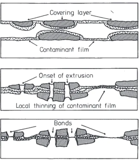
In cold welding, the bond can be established when two clean surfaces come into direct contact with themselves. The noticeable differences in weld-ability of numerous materials result from presence of contaminated films on the surface of these materials (Conrad & Rice, 1970; Sherwood & Milner, 1969). The surface preparation is required in order to re-move the contaminations and obtain successful bonding. The most commonly used method is de-greasing followed by scratch-brushing, which plays an additional and important role along with the cleaning function, namely, it creates a work hard-ened, brittle covering layer on the material surface (Bay, 1983). This layer arises directly on the surface of metal, so that the oxide scale cannot came into intimate contact with metal in these areas. During deformation the cover layer breaks and the pressure causes extrusion of the not oxidised metal through appearing cracks omitting the contaminant film (fig-ure 1). This leads to direct contact between virgin metal surfaces resulting in bonding establishment (Bay, 1983).
Fig. 1. Bonding mechanism during cold welding for scratch-brushed surfaces (Bay, 1986).
The quality of bonding can be evaluated visually by using optical and scanning electron microscopy (Ghafari-Gousheh et al., 2015) or mechanically, using peeling test (Manesh & Shahabi, 2009). Addi-tionally, the peeling test allows for determination of bond strength.
Nowadays, manufacture of multilayered materi-als with refined grains is becoming more common.
In the last two decades, nanostructured materials attracted widespread interest due to their superior mechanical properties, such as high yield and ulti-mate strengths comparing to the analogous polycrys-talline coarse-grained metals and alloys (Gleiter, 1989; Roland et al., 2007; Roland et al., 2009). However, their ductile properties are much lower, which is directly related to the volume fraction of the refined grains in these materials (Chen et al., 2005; Muszka et al., 2007). Ultrafine-grained struc-tures can be obtained by using of various severe plastic deformation (SPD) processes, such as Accu-mulative Roll Bonding (ARB), Equal Channel An-gular Extrusion (ECAE) or High Pressure Torsion (HPT). Moreover, it has been proved that recently developed Surface Mechanical Attrition Treatment (SMAT) is able to refine the grains in the surface layer to the nanometre scale (Lu & Lu, 1999; Roland et al., 2005; Roland et al., 2006). SMAT allows for obtaining bulk materials with limited depth of re-fined grains at the surface layer, which is not suffi-cient for enhancement of their mechanical properties and usually cause rapid saturation of the yield strength (Waltz et al., 2009b). Mechanical properties can be improved through increase of the volume fraction of the refined grains. Combining SMAT technique used for grain refining at the surface layer of the material with subsequent thermomechanical processing (TMP) allows for obtaining metallic ma-terials with multilayered bulk structure and the in-creased volume fraction of the refined grains. TMP is used for joining of the nanostructured metallic platters together. Such duplex techniques can be used to produce materials for structural applications with enhanced yield and ultimate strength, while conserving an acceptable elongation to failure. However, bonding imperfections between platters can result in significant deterioration of mechanical properties of such multilayered materials. Among the reasons of weakening the interfaces are impuri-ties deposited on the surface and interfacial oxida-tion that is more pronounced at elevated tempera-tures (Bajda et al., 2015; Waltz et al., 2009a).
C
OM
P
U
TE
R
M
ETHO
DS I
N
M
ATER
IA
LS
S
CI
EN
CE
grain structures and altered interactions between them comparing with their coarse-grained counter-parts. Additionally, interfacial oxidation occurs dur-ing TMP at high temperatures, which causes bond-ing imperfections and makes materials joinbond-ing much more difficult. Moreover, the diffusion rate within the nanostructured surface layers is higher than for coarse-grained materials due to the increased grain boundary density (Ralston & Birbilis, 2010). This have a dual effect on corrosion behaviour that de-pends on the external environment. An improvement of the corrosion resistance of the nanostructured surface layers has been reported in passivating elec-trolytes, while a decrease has been shown in depas-sivating electrolytes (Gupta & Birbilis, 2015; Liu et al., 2010). Furthermore, SMAT introduces surface defects (e. g., cracks), which has deleterious effect on corrosion performance. However, low tempera-ture annealing can be applied to such materials to remove the surface imperfections causing some im-provement of oxidation resistance compared to coarse-grained materials (Wang & Li, 2002; Wang & Li, 2003).
In the present study, the constrained compres-sion testing technique was applied for bonding of 316L stainless steel platters together. The aim of the whole project, which is divided by consecutive stag-es, is better understanding of the highly reactive interfaces behaviour of nanostructured multilayered
metallic materials. In order to be able to compare behaviour of nanostructured material with coarse-grained one, the goal of this first step of the project is to obtain joint between coarse-grained metallic parts via the developed compression technique and to analyse material response during the processing. In order to avoid influence of high temperature oxi-dation on the interfaces, compression tests were performed at room temperature. A specially de-signed hollow die and rounded tools were used. Numerical simulation based on FE methodology was applied in order to examine the details of material behaviour. The Abaqus/Standard FE software was used for the calculations. Strain and stress localisa-tions were identified and discussed in the work.
2. EXPERIMENTAL PROCEDURE – CONSTRAINED COMPRESSION TEST
The constrained compression test was carried out on hydraulic press of maximum capacity 5000 kN at room temperature and without lubrica-tion. Eight cylindrically-shaped plates of 1 mm thickness and 10 mm diameter were cut by using
waterjet cutting technique from 316L stainless steel cold rolled sheet with 20-50 μm initial grain size and chemical composition presented in table 1.
The hollow die of 8 mm thickness, 30 mm outer diameter and 10 mm inner diameter was cut by laser also from 316L steel. After placing the plates into Table 1. Chemical composition of 316L stainless steel used in research.
Element C Si Mn P S Cr Ni Mo N
Content, [%] 0.02 0.488 0.9 0.0315 0.0002 16.998 11.039 2.03 0.0287
C
OM
P
U
TE
R
M
ETHO
DS I
N
M
ATER
IA
LS
S
CI
EN
CE
the hollow die (figure 2a), the package was undergo-ing compression between the specially designed rounded tools with 45% and 55% reduction (figure 2b). The indicated values were obtained at the centre of such package, where reduction level is the high-est.
The bottom tool was fixed during compression while the speed of the top tool was chosen to be 7.2 mm/s. The radius, height, width and length of the tools were the following: 250, 150, 88 and 195 mm respectively. The rounded tool shape changing the deformation conditions within the compressed pack-age allowed for generation of the relevant shearing necessary for bonding at the interfaces (Quadir et al., 2008). The specifically designed tool shape also allowed for reduction of forces required for such compression, therefore higher reduction levels were achieved using the same testing rig comparing with conventional forging.
Before the specimens were subjected to the compression testing, all the plate surfaces were de-greased with acetone and subjected to both sides scratch-brushing. Immediately after that, they were placed into the hollow die. Then, the package was undergoing compression without delay. The time interval between the scratch-brushing and the com-pression operation was less than a minute. The short time interval was necessary, because it has been
shown earlier that the bond strength decreases with increase of delay times between the surface prepara-tion and the joining process (Jamaati & Toroghinejad, 2011).
The compression load was applied simultaneous-ly on the plates and the hollow die in this technique. The external constraint has a noticeable impact on material flow (Eskandari et al., 2013). Thus, the designed hollow die confining the material flow during the compression significantly disturbed the local deformations around the interfaces.
3. NUMERICAL MODELLING
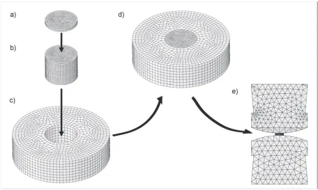
3D FE based model of the constrained compres-sion test has been developed and applied for the analysis (figure 3).
Eight cylindrically-shaped steel plates were placed one over another (figure 3b). The thickness
and diameter of each plate was 1 mm and 10 mm respectively, reflecting the actual sizes of the speci-mens. The hollow die thickness, the outer and inner diameter was 8 mm, 30 mm and 10 mm, respectively (figure 3c). The packed plates were inserted into the model of the die (figure 3d) and finally, the whole package was placed between the two rounded shape rigid tools, each of 250 mm radius, as it is shown in figure 3e.
C
OM
P
U
TE
R
M
ETHO
DS I
N
M
ATER
IA
LS
S
CI
EN
CE
The standard isotropic Coulomb friction model has been assumed in the numerical calculations. No relative motion between surfaces occurs if the equivalent frictional stress
τ
eq is less than thecriti-cal stress
τ
cr, which is proportional to the contact pressure, as it is shown in the following equations:2 2 2
1
τ
τ
τ
eq = + (1)p
cr
μ
τ
= (2)where p is the contact pressure and μ is the friction coefficient. The critical stress is defined as follows:
)
,
min(
μ
τ
maxτ
cr=
p
(3)where
τ
max is an adjustable parameter. The slip occurs when the equivalent frictional stress reaches the critical stress value. The direction of the slip coincides with the frictional stress, which can be expressed by equation (4):eq i
eq i
γ
γ
τ
τ
=
(4)where
γ
i is the slip rate in i direction andγ
eq is the equivalent slip velocity:2 2 2
1 γ
γ
γeq = + (5)
The condition of no relative motion between the surfaces that come into contact is approximated by stiff elastic behaviour. Therefore, the relative motion from the zero shear stress position is determined by a critical slip
γ
cr value, which was set as 0.5% of the average length of all contact elements.The scratch-brushing operation changes the sur-face roughness, hence different friction coefficients have been assumed between the plate surfaces, such as μ = 0.4, between the plate side surfaces and the hollow die inner surface, μ = 0.3, between the outer
plates and the tools surfaces, μ = 0.35, and between the die and the tool surfaces, μ = 0.3.
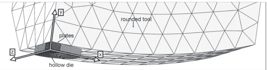
The calculations were performed using the mod-el consisting of 16342 mod-elements including 5558 quadratic tetrahedral elements of type C3D10 repre-senting the tool and 10784 linear hexahedral ele-ments of type C3D8R representing the both plates and the die. The symmetric boundary conditions shown in figure 4 were applied for the modelling. The boundary conditions were the following:
− zero-X displacements for nodes lying on the
YZ-plane (Ux = 0);
− zero-Y displacements for nodes lying on the
XZ-plane (Uy = 0);
− zero-Z displacements for nodes lying on the
XY-plane (Uz = 0).
The same elastic-plastic material model with iso-tropic hardening has been chosen for both the plates and the hollow die. Its Young’s modulus, Poisson’s ratio and the yield stress were assumed as the fol-lowing: 190 GPa, 0.3 and 290 MPa, respectively. The stress-strain relationship was introduced into the model as the following equation (Petit et al., 2012):
733 . 0
1255
290 ε
σ = + ⋅ (6)
where
ε
is the effective plastic strain.Various compression reductions from 18% to 55% have been applied during the numerical analy-sis.
The Newton-Raphson’s method was chosen as a numerical technique for solving the nonlinear equi-librium equations primary due to better rate of con-vergence comparing to other methods.
4. RESULTS AND DISCUSSION
C
OM
P
U
TE
R
M
ETHO
DS I
N
M
ATER
IA
LS
S
CI
EN
CE
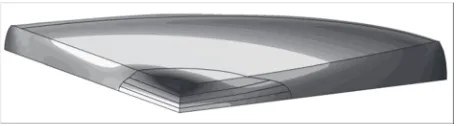
with their model representation are presented in figure 5.
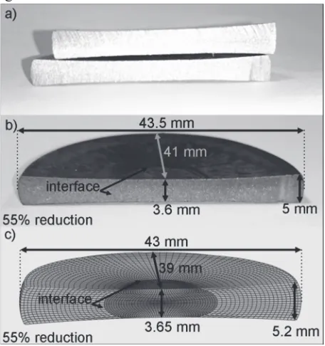
Fig. 5. Sample cross-sections after constrained compression test: a,b) experimental, c) FE model.
Figure 5a illustrates the compressed package us-ing 45% (top) and 55% (bottom) reductions. The characteristic profile of the deformed package can be observed in the figure with lower thickness in the middle and the curved side surface due to barrelling. The similar shape and dimensions of the package were obtained during the numerical analysis (figure 5c). The experimentally obtained profile of the inter-face between the die and the plates also exhibits good agreement with the results of prediction (figure 5b and c) conforming to the conventional viewpoint that the material flows easier towards the sides at half height of the package thickness and its flow is more difficult near the top and bottom surfaces. This is due to the relatively high friction coefficient be-tween the package and tool surfaces. The maximum pressing force achieved experimentally at 55% re-duction was about 3500 kN, while the corresponding one obtained numerically was about 3300 kN.
C
OM
P
U
TE
R
M
ETHO
DS I
N
M
ATER
IA
LS
S
CI
EN
CE
No sliding between the plates was registered numerically when the hollow die was applied, while relative movement between the plates was noticea-ble during compression without the hollow die. This indicates that presence of the die improves the con-ditions required for obtaining successful bonding.
The effective strain predicted during the com-pression test for the consequent stages of 18%, 34%, 45% and 55% reduction is shown in figure 6. At the beginning of the process, the material is mostly de-formed at the die surface, due to shear stresses re-sulted from the tool shape, and also in the middle of the package volume creating a characteristic cross-shaped pattern (figure 6a). In the following stage, as it is seen in figure 6b, the deformed earlier regions expand accumulating the strain. When compression reaches 45% reduction (figure 6c), the strain in the mentioned above surface areas exceeds the strain in the cross-section centre. When the reduction level reaches 55% (figure 6d), the effective strain increas-es significantly, increas-especially in thincreas-ese top areas. It is due to higher shear stresses that are developed in the area during the whole process. The stresses are much higher than in the case of using flat tools (figure 8). The lowest deformation occurred directly in the middle of the surface at the place of the first contact with the tool. Even at such large reduction, the thickness of the outermost plates was similar to their initial thickness, in contrast to the thickness of the inner plates that were deformed significantly. It has to be mentioned that the closer to the middle the
plate is placed within the package, the more pro-nounced is its reduction and, consequently, the larg-er is its diametlarg-er. This is due to the influence of the forces acting simultaneously from both top and bot-tom tools. The portion of the material at the top is pressed into the bottom one and vice versa. This
causes both high stresses at the interfaces in the middle of the package and large height reductions of the plates located in this region. The deformed mate-rial flows in X direction increasing the plates
diame-ter.The phenomenon was also observed
experimen-tally (figure 5b). The strain distribution observed within the plates favours the conclusion that the closer to the package centre the chances for success-ful bonding are higher. Furthermore, the grain size should be finer at these areas as well. The tools should also favour the grain refinement at lateral parts of the outer plates because of the direct contact between them and the plates under the deformation.
C
OM
P
U
TE
R
M
ETHO
DS I
N
M
ATER
IA
LS
S
CI
EN
CE
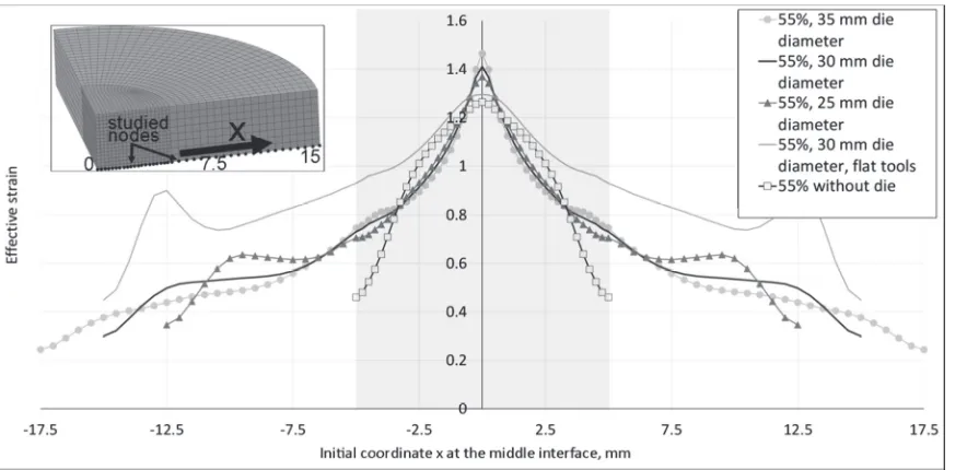
fied: the contact surface of the tools is rounded and the hollow die is used for the constrained compres-sion test. The specific tool shape favours generation of additional shear stresses, which contribute to the obtained effective strain values. A hollow die con-strains the lateral expansion of the plates increasing in such way stresses within them that results in ob-taining greater effective strains than for the case without the hollow die application. If the rounded tools are used without a hollow die, the correspond-ing effective strains become lower than in the case of using flat tools with the hollow die. Larger die outer diameters allow for achievement of larger de-formations. Although, obtaining the same reductions requires higher pressures.
As can be seen in figure 8, the highest effective strains are achieved at the package surface when both 35 mm diameter die and the rounded tools are used. Smaller strains are obtained in the case of the flat tools. However, it has to be mentioned that in the second case, the large deformations occur not in the plate but in the die itself, at 8 mm distance from the plate centre. It results from the fact, that the flat tool surface acting uniformly on the whole package surface, while the stress influenced by application of the rounded tool surface is the highest at the centre and gradually decreases with the distance from the package centre. Thus, the pressure induced by the flat tool exceeds the one generated by the rounded tool at some distance from the centre causing the
Fig. 8. The effective strain predicted at the nodes located at the package surface along the symmetry axis for the different geometrical conditions. Grey colour area indicates coordinates of nodes representing plates.
C
OM
P
U
TE
R
M
ETHO
DS I
N
M
ATER
IA
LS
S
CI
EN
CE
observed high strains in the die. The deformations will have less noticeable effect on bonding between plates than in the cases when both the rounded tools and the hollow die are used simultaneously. When the hollow die is not used, the strain at the nodes doesn’t grow as the distance from the centre increas-es above 2 mm. It favours the conclusion that the hollow die provides more beneficial conditions for obtaining reliable bonding between the platters in processing of multilayered metallic materials.
Figure 9 shows the effective strain predicted at the interface at half-value of the package thickness. It can be noticed that the largest deformations are achieved in the vicinity of the centre, namely, within 0.5 mm from the centre assuming both the hollow die and rounded tools are used. Similarly to the pre-vious case, larger effective strains are observed when dies with larger outer diameters are used. The highest strains are achieved at distances longer than 0.5 mm from the centre in the case of using flat tools. At the same time, the lowest effective strains were predicted at the centre during compression without a die using rounded tools. They become higher at distances longer than 0.5 mm from the midpoint. However, the bonding was not obtained experimentally during compression without a die allowing for suggestion that obtaining high effective strains near the sample centre is the most significant for successful bonding.
Fig. 10. Schematic representation of the effective stress locali-sations during constrained compression testing. (One-eighth of the package. Bright colour corresponds to higher stresses).
As it can be noticed from figure 10, the areas of the highest effective stresses are located mainly at the surface layer of the die and at the interface in the vicinity of the plate centre during the constrained compression test. It has to be mentioned, that the areas of the die surface layer, where the high stresses were observed, are vulnerable to cracking requiring reasonable accuracy during experimentation. Never-theless, the described constrained testing procedure allows for detailed quantitative analysis of the micro events taking place at the interfaces during pro-cessing of multilayered metallic materials including evolution of the microstructure and events related to interface oxidation leading to better understanding
of mechanisms responsible for achievement of the desirable mechanical properties.
5. CONCLUSIONS
Development of the testing procedure leading to understanding of mechanisms responsible for pro-cessing of multilayered metallic materials is consid-ered in this work paving the way towards processing of multilayered nanostructured metallic materials. The performed numerical analysis of strain and stress distributions within the package of eight cy-lindrically-shaped steel plates during constrained compression testing using the hollow die of different shapes supported by the relevant experimental re-sults allowed for clarification of the specific role of the hollow die in terms of achievement a desirable stress (strain) state around the interfaces of the mul-tilayered material. The numerical results are in good agreement with the available experimental evidence. Based on the observations and discussion above, the following conclusions can be drawn:
1. The hollow die significantly improved
mechani-cal conditions at the interfaces allowing for ob-taining successful bonding between steel platters during compression.
2. Achievement of the highest possible effective
strains within the proximity to the centre of the package was critical for obtaining a successful bonding during the test.
3. The mentioned effective strains can be obtained using the hollow die and the rounded tools.
4. The larger the diameter of the hollow die, the
larger effective strain at the sample centre can be achieved. Although, it would require higher pressures to achieve the same reduction.
5. The thickness of the outermost plates is reduced insignificantly in comparison with inner plates of the package during the test.
ACKNOWLEDGEMENT
The support from the National Science Centre, Poland (grant no. DEC-2013/09/B/ST8/00141) is greatly appreciated.
REFERENCES
C
OM P U TE RM
ETHO DS I NM
ATER IA LSS
CI EN CEBay, N., 1983, Mechanisms Producing Metallic Bonds in Cold Welding, Weld. Reseach Suppl., 62, 137-142.
Bay, N., 1986, Cold welding: Part 1 Characteristics, bonding mechanisms, bond strength, Met. Constr., 18(8,10), 369-372.
Bay, N., Clemensen, C., Juelstorp, O., Wanheim, T., 1985, Bond Strength in Cold Roll Bonding, CIRP Ann. - Manuf. Technol., 34(1), 221-224.
Chen, X. H., Lu, J., Lu, L., Lu, K., 2005, Tensile properties of a nanocrystalline 316L austenitic stainless steel, Scr. Mater., 52(10), 1039-1044.
Conrad, H., Rice, L., 1970, The cohesion of previously fractured Fcc metals in ultrahigh vacuum, Metall. Trans., 1(11), 3019-3029.
Eskandari, M., Zarei-Hanzaki, A., Pilehva, F., Abedi, H. R., Fatemi-Varzaneh, S. M., Khalesian, A. R., 2013, Ductility improvement in AZ31 magnesium alloy using constrained compression testing technique, Mater. Sci. Eng. A, 576, 74-81.
Ghafari-Gousheh, S., Hossein Nedjad, S., Khalil-Allafi, J., 2015, Tensile properties and interfacial bonding of multi-layered, high-purity titanium strips fabricated by ARB process, J. Mech. Behav. Biomed. Mater., 51, 147-153. Gleiter, H., 1989, Nanocrystalline materials, Prog. Mater. Sci.,
33(4), 223-315.
Gupta, R. K., Birbilis, N., 2015, The influence of nanocrystalline structure and processing route on corrosion of stainless steel: A review, Corros. Sci., 92, 1-15.
Jamaati, R., Toroghinejad, M. R., 2011, The role of surface preparation parameters on cold roll bonding of aluminum strips, J. Mater. Eng. Perform., 20(2), 191-197.
Li, L., Nagai, K., Yin, F., 2008, Progress in cold roll bonding of metals, Sci. Technol. Adv. Mater., 9(2), 1-11.
Liu, L., Li, Y., Wang, F., 2010, Electrochemical Corrosion Behavior of Nanocrystalline Materials - a Review, J. Mater. Sci. Technol., 26(1), 1-14.
Lu, K., Lu, J., 1999, Surface nanocrystallization (SNC) of metallic materials-presentation of the concept behind a new approach, J. Mater. Sci. Technol., 15(3), 193-197. Manesh, H. D., Shahabi, H. S., 2009, Effective parameters on
bonding strength of roll bonded Al/St/Al multilayer strips, J. Alloys Compd., 476(1-2), 292-299.
Milner, D. R., Rowe, G. W., 1962, Fundamentals of Solid-Phase Welding, Metall. Rev., 7(1), 433-480.
Mori, K. I., Bay, N., Fratini, L., Micari, F., Tekkaya, A. E., 2013, Joining by plastic deformation, CIRP Ann. - Manuf. Technol., 62(2), 673-694.
Muszka, K., Majta, J., Hodgson, P. D., 2007, Study of the grain size effect on the deformation behavior of microalloyed steels, In Proceedings of Materials Science And Technology, Detroit MI: Association for Iron and Steel Idustry 6, 493-504,.
Pawlicki, M., Drenger, T., Pieszak, M., Borowski, J., 2015, Cold upset forging joining of ultra-fine-grained aluminium and copper, J. Mater. Process. Technol., 223, 193-202. Petit, J., Waltz, L., Montay, G., Retraint, D., Roos, A., François,
M., 2012, Multilayer modelling of stainless steel with a nanocrystallised superficial layer, Mater. Sci. Eng. A, 536, 124-128.
Quadir, M. Z., Wolz, A., Hoffman, M., Ferry, M., 2008, Influence of processing parameters on the bond
toughness of roll-bonded aluminium strip, Scr. Mater., 58(11), 959-962.
Ralston, K. D., Birbilis, N., 2010, Effect of grain size on corrosion, Corrosion, 66(7), 1-4.
Roland, T., Retraint, D., Lu, K., Lu, J., 2005, Generation of nanostructures on 316L stainless steel and its effect on mechanical behavior, Mater. Sci. Forum, 490-491, 625-630.
Roland, T., Retraint, D., Lu, K., Lu, J., 2006, Fatigue life improvement through surface nanostructuring of stainless steel by means of surface mechanical attrition treatment, Scr. Mater., 54(11), 1949-1954.
Roland, T., Retraint, D., Lu, K., Lu, J., 2007, Enhanced mechanical behavior of a nanocrystallised stainless steel and its thermal stability, Mater. Sci. Eng. A, 445-446, 281-288.
Roland, T., Ya, M., Retraint, D., Lu, K., Lu, J., 2009, A New Multilayered Nanostructured Composite Material Produced by Assembling SMA-Treated Thin Plates, J. Mater. Sci. Technol., 20(Supl.), 55-58.
Sherwood, W. C., Milner, D. R., 1969, The Effect of Vacuum Machining on the Cold Welding of Some Metals, J. Inst. Met., 97, 1-5.
Waltz, L., Retraint, D., Roos, A., Olier, P., 2009a, Combination of surface nanocrystallization and co-rolling: Creating multilayer nanocrystalline composites, Scr. Mater., 60(1), 21-24.
Waltz, L., Retraint, D., Roos, A., Olier, P., Lu, J., 2009b, High Strength Nanocrystallized Multilayered Structure Obtained by SMAT and Co-Rolling, Mater. Sci. Forum, 614, 249-254.
Wang, X. Y., Li, D. Y., 2002, Mechanical and electrochemical behavior of nanocrystalline surface of 304 stainless steel, Electrochim. Acta, 47(24), 3939-3947.
Wang, X. Y., Li, D. Y., 2003, Mechanical, electrochemical and tribological properties of nano-crystalline surface of 304 stainless steel, Wear, 255(7-12), 836-845.
Yanagimoto, J., Oya, T., Kawanishi, S., Tiesler, N., Koseki, T., 2010, Enhancement of bending formability of brittle sheet metal in multilayer metallic sheets, CIRP Ann. - Manuf. Technol., 59(1), 287-290.
W KIERUNKU WYTWARZANIA WIELOWARSTWOWYCH MATERIAŁÓW METALICZNYCH – PRÓBA OGRANICZONEGO
ŚCISKANIA
Streszczenie
oprogra-C
OM
P
U
TE
R
M
ETHO
DS I
N
M
ATER
IA
LS
S
CI
EN
CE
mowania ABAQUS/Standard ujawniła obszary lokalizacji naprę -żeń i odkształceń wewnątrz wielowarstwowej struktury, a także inne elementy, które zostały opisane w pracy. Wyniki analizy numerycznej są zgodne z wynikami badań doświadczalnych.