Received November 3, 2016, accepted December 22, 2016, date of publication January 18, 2017, date of current version July 24, 2017.
Digital Object Identifier 10.1109/ACCESS.2017.2655345
Universal and Dynamic Clustering Scheme
for Energy Constrained Cooperative
Wireless Sensor Networks
MUHAMMAD KAMRAN NAEEM1, (Student Member, IEEE),
MOHAMMAD PATWARY2, (Senior Member, IEEE) AND
MOHAMED ABDEL-MAGUID3, (Senior Member, IEEE)
1Faculty of Computing, Engineering and Sciences, Staffordshire University, Stoke-on-Trent ST4 2DE, U.K.
2Faculty of Computing, Engineering and the Built Environment, Birmingham City University, Birmingham B5 5JU, U.K. 3Department of Science and Technology, University of Suffolk, Ipswitch IP4 1QJ, U.K.
Corresponding author: Muhammad Kamran Naeem ([email protected])
ABSTRACT Energy conservation is considered to be one of the key design challenges within resource constrained wireless sensor networks that leads the researchers to investigate energy efficient protocols with some application specific challenges. Dynamic clustering is generally considered as one of the energy conservation techniques; but unbalanced distribution of cluster heads, highly variable number of sensor nodes in the clusters and high number of sensor nodes involved in event reporting tend to drain out the network energy quickly resulting premature decrease in network lifetime. In this paper, a dynamic and cooperative clustering and neighborhood formation scheme is proposed that is expected to evenly distribute energy demand from the cluster heads and optimize the number of sensor nodes involved in event reporting. Assuming multiple sensors will form a cluster, while responding to an event to report to the fusion center. However, all the sensor nodes are assuming to report the sensing parameters to a cluster-head; which are to be summarized and then report it to fusion center. The transmission of the same event data from multiple sensors within the cluster at different distances with single or multiple antennas to the cluster-head with similar antenna characteristics can be realized as multiple-input multiple-output (MIMO) channel set up as found in the literature. Such realization among clusters of MIMO channel and existence of a feedback channel between the clusters and fusion center is the key of the proposed framework. The dynamic behavior has been adopted within the framework with a proposed index derived from the received measure of the channel quality, which has been attained through the feedback channel from the fusion center. The dynamic property of the proposed framework makes it robust against time-varying behavior of the propagation environment. The proposed framework is independent of the nature of the sensing application, providing with universal behavior. From simulation results, it is observed that the proposed clustering scheme enhances network lifetime by 24.5% and 36% as compared to existing schemes e.g. DDEEC and EDDEEC respectively. Furthermore, it is validated by simulation results that the proposed framework provides a trade-off model between network lifetime and transmission reliability.
INDEX TERMS Adaptive resource selection, collaborative sensing, cooperative transmission, channel quality index (CQI), dynamic clustering, quality of service (QoS), virtual MIMO, wireless sensor networks.
I. INTRODUCTION
Wireless Sensor Networks (WSNs) are commonly deployed to serve wide range of potential applications e.g. environ-mental monitoring, health monitoring, battlefield monitoring etc. Regardless of the nature of sensing application require-ments WSNs are usually formed with spatially dispersed and dedicated sensor nodes which collectively monitor and
distribute information to the desired destinations. Sensor nodes are inexpensive resource constrained devices that consist of a sensor, embedded processors, limited memory, low power radio, and normally powered by battery. WSNs usually suffers from inevitable problems because of resource constrained sensor nodes deployed randomly in hostile envi-ronments which make it difficult to change or replace their
12318
2169-35362017 IEEE. Translations and content mining are permitted for academic research only.
batteries as discussed in [1]. Consequently, lifetime enhancement is one of the key issue while designing the WSNs regardless of the type of application, without compromising the required quality of service.
To achieve scalability and energy efficiency within WSNs, clustering is defined that virtually divides the sensor nodes of the whole network into logical groups. It also enhances load balancing, fault tolerance and network connectivity within the network as described in [2]. Generally, cluster heads are elected within WSNs to perform special tasks for its sensor nodes e.g. coordination among sensor nodes, data aggrega-tion, communication with other cluster heads and fusion cen-ter receiver etc. The cluscen-ter heads election cricen-terion is usually based on certain parameters i.e. residual energy, distance from fusion center receiver etc. As a result of aforementioned tasks, the energy of cluster heads drains out at much faster rate than the other sensor nodes within the network. Therefore, the self-organization of the WSNs is a desirable feature as no centralized or external entity is required. Dynamic clustering is introduced within WSNs which is expected to balance the energy consumption among the sensor nodes by re-electing the cluster heads and redefining the cluster bound-aries throughout the network; hence enhance the lifetime of the WSN as discussed in [3]. Most of the dynamic clustering schemes presented in the literature as described in [4] are based on random selection of cluster heads which results in uneven distribution of cluster heads that leads to low network coverage and uneven energy consumption. As a result, it also increases the chance of selecting sensor nodes with low energy level as cluster heads which will force frequent re-clustering. Subsequently, controlled size clustering is one of the solutions to overcome the aforementioned challenges that is expected to conserve energy by evenly distributing the energy demand among sensor nodes throughout the network. Within WSNs, most of the energy consumed while com-munication, especially data transmission to fusion cen-ter receiver which is denoted as long-haul transmission. Generally, conventional single node transmission techniques are used for long-haul communication. But, such high depen-dency on a single node while long-haul transmissions may lead to reliability risk in severe network conditions such as least amount of available energy at a sensor node or deep channel fading etc. Hence, energy efficient communication schemes are needed to be defined to focus on minimizing the energy consumption during communication. Cooperation among sensor nodes while data transmission allows resource saving within WSNs by implementing virtual MIMO‡ con-cepts for energy efficient communication to increase reliabil-ity and enhance energy efficiency [5].
The power consumption of a sensor node is directly propor-tional to the uncertainty of channel propagation conditions. So, one of the design challenges of WSNs is to make them
‡The basic concept of virtual MIMO is the cooperation among
multi-ple devices into virtual antenna array to attain the advantages of MIMO communication.
adaptive with the dynamic propagation environmental condi-tions of radio frequency to guarantee the quality of service based on application requirements. The required quality of service is generally defined in terms of error rate that can be guaranteed by adopting dynamic behavior according to the time-varying conditions of propagation environment. It is also expected to obtain maximum transmit-receive reliability with optimum usage of radio resources such as power and bandwidth. To obtain maximum optimization performance, knowledge of the channel quality features at the transmitter is required. Hence, classification of such channel quality features as estimated at the receiver can be fed back to the transmitter with negligible spectral resources as required.
As discussed earlier, wireless communication is the most energy consuming task within WSNs. A new approach for an improved lifetime of wireless sensor nodes is required that is expected to process the sensing data locally. Each sensor node is expected to decide locally whether to transmit the sensed data to cluster head based on the predefined application specific threshold value provided by fusion center receiver. To reduce the unnecessary communication between sensor nodes and cluster heads for time-driven reporting mode, cluster heads are expected to aggregate the data in order to remove redundant information. All the cluster heads are also expected to collaborate with each other. In some applications, sensor measurements are sent directly to the fusion center receiver from the sensor nodes e.g. traffic surveillance system to monitor traffic on congested roads, watches to monitor health (e.g. blood pressure, pulse rate etc.), wireless motion sensor for the monitoring of stroke patients, etc. In most of the applications, sensor nodes are densely deployed in harsh environments to monitor large scale areas e.g. envi-ronmental monitoring, infrastructure protection, agriculture, water management, military surveillance, etc. The energy and sensing range of a sensor node is limited in such scenarios. So, sensor nodes can be organized in a multi-hop fashion that is expected to achieve long distance communication and life-time improvement of the network. Within WSNs, the fusion center receivers are responsible to collect the information from the network, process and analyze the information and send instructions to the sensor nodes within the network. They are usually connected with internet through wireless or wired communication such that the sensing data can be requested at any time by an end user.
to provide a trade-off model between energy conservation and detection reliability. The main contributions of this paper are as follows:
1) A dynamic clustering as well as neighborhood forma-tion framework for WSNs is proposed where collab-orative sensing is permitted. The proposed framework provides an energy efficient solution by uniformly dis-tributing the network load among sensor nodes and carefully selecting the candidate sensor nodes for event reporting.
2) The proposed framework is universal in nature for its functionality requirement within a WSN, i.e. inde-pendent of the sensing parameters. This provides the system design engineer with a tool for lifetime approxi-mation modelling to configure the network for a diverse range of applications by fine-tuning the following parameters i.e. cluster head selection threshold and neighborhood selection criterion.
3) The dynamic behavior of the proposed framework is adopted with a proposed channel quality index-ing (CQI) scheme in the context of WSNs. This scheme provides a trade-off model for transmission reliability and network lifetime by dynamically reconfiguring the network according to radio frequency propagation environment conditions while maintaining required quality of service.
In this paper, it is assumed that the fusion center is equipped with multiple antennas, has unlimited energy and its coor-dinates are known. It is also assumed that the dimensions of the sensing field are known and the coordinates of all the sensor nodes are implicitly deterministic. The rest of the paper is organized as follows: The literature review is elaborated in section II; the system model is described in section III; the proposed frameworks for time-driven and event-driven are presented in section IV; network lifetime models are defined in section V; performance analysis of the proposed frameworks have been presented in section VI along with the comparison of existing frameworks to evaluate the performance of the proposed framework followed by conclusion in section VII.
II. RELATED WORK
The state of the art research studies that provide solutions to resolve the issues within WSNs are elaborated in this section such as uniform energy consumption among sensor nodes within the network by performing network segmentations, and reliable transmission by introducing cooperation between the sensor nodes. Existing network segmentation and lifetime approximation techniques in the literature can be grouped into two categories: time-driven sensing and event-driven sensing.
A significant amount of research has been conducted in the literature for lifetime approximation of time-driven sensing scenarios. Low Energy Adaptive Clustering Hierar-chy (LEACH) scheme is proposed in [6] and [7] that desig-nate cluster heads with a predetermined random probabilistic
approach which can lead to early energy depletion because the sensor nodes with low residual energy can be elected as cluster heads. A residual energy and communication cost based hybrid energy efficient distributed clustering algorithm scheme is proposed in [8]. In this scheme, cluster heads are elected through iteration process by constant communication between the candidate cluster heads and their neighboring sensor nodes which results in extra communication cost. Authors in [9] proposed a distributed energy efficient clus-tering algorithm that considers the ratio of residual energy of candidate cluster heads and average network energy for the election of cluster heads that results extra load on the network by calculating the average energy of the network.
The aforementioned schemes perform cluster heads selec-tion randomly that can lead to unbalanced energy consump-tion throughout the network. To address this issue authors in [10]–[14] proposed that fewer number of nodes should be allocated to the clusters which are near to the sink in order to reduce the cost of inter-cluster communication. However, this approach of clustering can result significant amount of traffic load on the cluster heads near to the sink as discussed in [15]. Authors in [16] discussed the significance of uniform size clustering in order to balance the communication overhead and energy consumption in the network.
Considering WSNs for detection and reporting of events is another attractive approach for significant amount of appli-cations. Authors in [17] discussed that the occurrence of events are generally considered as random and transient which involves the handling of large amount of sensing data that can lead to uneven energy consumption. To overcome this issue, clustering algorithms are proposed in [18] and [19], that consider the residual energy and distance of sensor nodes as cluster head election criteria. Local and global decision based event detection protocols are presented in [20] and [21]. The authors claimed that the proposed schemes conserve energy by reducing transmissions and minimize error probability through local and global decisions respectively. But in order to ensure the detection reliability of an event, it must be detected by a group of sensor nodes. The spatiotemporal correlation of the sensed data can achieve higher energy efficiency and detection reliability as discussed in [22].
explicit knowledge of channel quality information at the transmitter side. Such channel quality information can be estimated and classified at the receiver and fed back to the transmitter with negligible spectral resources as discussed in [27] and [28].
The research studies in the literature consider time-driven and event-driven scenarios separately and do not provide a unified solution. In this paper, a dynamic clustering and neighborhood formation scheme is proposed that provides a universal framework which is independent of the nature of sensing application. It is expected that the proposed frame-work will provide an energy efficient solution by rotating the role of cluster head among all the sensor nodes while trying to keep the size of the clusters uniform and minimizing the frequency of re-clustering. Furthermore, considering the residual energy threshold in cluster heads selection process and their location in the network, the proposed framework is expected to avoid unbalanced energy consumption and energy holes in the network. In order to attain transmission reliability, the dynamic behavior is adopted to minimize the effect of variable channel conditions on data transmission. Such adaptation can be achieved by deriving an index from the received measure of channel quality that is attained at the transmitter through a feedback link from the fusion center. The dynamic behavior of the proposed framework is expected to provide a robust solution against variable conditions of propagation environment. The system model of the proposed framework is presented in the following section.
III. SYSTEM MODEL
In this section, a WSN model is described, which assumes a random distribution of n number of sensor nodes within the sensing field of dimensions (A×B). Each sensor node is assumed to be capable of measuring homogeneous and het-erogeneous data sets based on the application requirements. It is assumed that the locations of the sensor nodes are implic-itly deterministic and all the sensor nodes within the network are homogenous in terms of processing and computational capability at initial deployment. LetSis a set of all the sensor
nodes in the network which is defined as:
S= {S1,S2, . . . ,Sn} (1)
whereS(.) represents the indexing of the sensor nodes. To
limit the communications overhead within large scale WSNs, several segmentation schemes have been proposed in the literature. Network segmentation is expected to achieve high energy efficiency, hence contribute to prolong the lifetime of WSNs [29]. In this Paper, the whole network is divided into non-overlapping uniform grids of dimensionsac×bc.
LetQis a set of all the grids within the network which is defined as:
Q= {Qj|j=1,2, . . . ,q} (2)
whereqis the number of grids in the network and each grid consists ofpjnumber of sensor nodes. The set of sensor nodes
within each grid can be defined as{Si|i=1,2, . . . ,pj}. The
sensor nodes within the network can be defined as:
n=q×
q
X
j=1
pj (3)
ConsiderQ(·)represent a set of sensor nodes within a grid,
thenjthgrid is represented asQjand defined as:
Qj= {Sij |i=1,2, . . . ,pj} (4)
whereSiqdenotesithsensor node of theqthgrid. In each grid, a sensor node is selected as cluster head to coordinate with other sensor nodes within the cluster based on certain criteria. Cluster heads act as coordinators between the member sensor nodes and fusion center receiver e.g. collect data from the sensor nodes, perform data aggregation, forward it to the fusion center, take instructions from the fusion center, etc. Dynamic cluster architectures are expected to gain energy efficiencies by selecting cluster heads in order to effectively react and adjust appropriately on network topology.
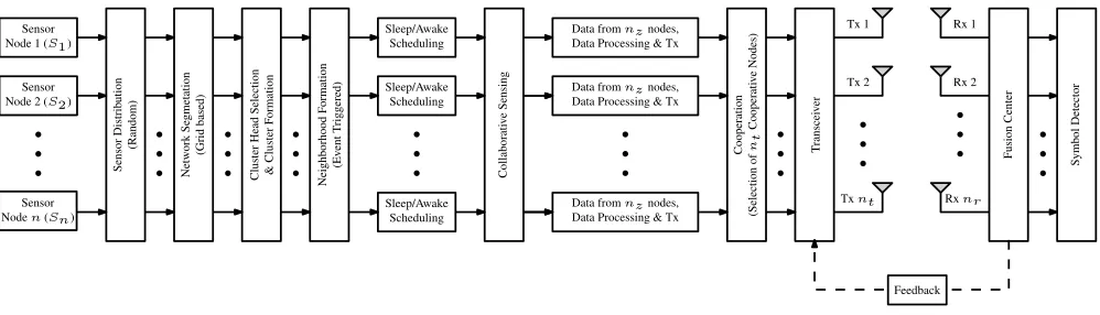
A typical system model proposed within the scope of this study is shown in Fig. 1. The transmitted data vector fromnt
number of transmitting sensor nodes is denoted as x and expressed as:
x=[x1,x2, . . . ,xnt]
T (5)
The received signal vector at fusion center can be expressed as:
y=Hx+n (6)
where y is the received signal vector with dimensions (nr ×1), His the Rayleigh fading channel matrix of size
(nr×nt) andnis the noise vector with dimensions (nr×1).
The noise is considered to be additive white Gaussian noise with zero mean and unity varianceσ2. The Rayleigh fading channel matrix is defined as:
H=
h(1,1) h(1,2) . . . h(1,nt)
h(2,1) h(2,2) . . . h(2,nt)
... ... ... ... h(nr,1) h(nr,2) . . . h(nr,nt)
(7)
wherehˆj,ˆidenotes the channel coefficients fromˆith
trans-mitter sensor node toˆjthreceiving antenna at the fusion center withˆi ∈ {1,2, . . . ,nt}andˆj ∈ {1,2, . . . ,nr}respectively.
It is also assumed that there is a feedback link between the sensor nodes and fusion center receiver which is expected to enable the sensor nodes to exploit channel conditions and adapt accordingly. Employment of the feedback channel requires cooperation between the sensor nodes and fusion center receiver. Fusion center receiver is expected to estimate the channel coefficients and fed-back channel state informa-tion to the network that can use this informainforma-tion to adapt the transmit signal to the channel.
IV. PROPOSED UNIVERSAL AND DYNAMIC CLUSTERING SCHEME (UDCS)
In order to conserve energy of sensor nodes within WSNs, it is expected to distribute the load of performing tasks among the sensor nodes to balance the energy consumption within the network, select optimum number of sensor nodes to report significant occurrences and to perform reliable com-munication to relay sensing data to fusion center receiver. Generally, sensing within WSNs can be realized into time-driven and event-time-driven scenario. In time-time-driven sensing, the sensor nodes relay acquired data to fusion center receiver on a periodic basis. While in event-driven sensing the sensor nodes are responsible to detect significant occurrences and report it to fusion center receiver. In this paper, a dynamic clustering and neighborhood formation scheme is proposed for time-driven and event-time-driven applications. Moreover, a universal framework is proposed for adaptive utilization of both the aforementioned sensing scenario to enhance its feasibility of implementation for a diverse range of applications. Moreover, the dynamic allocation of degree of cooperation based on channel propagation conditions is also considered. Within the proposed UDCS framework, all the decisions such as the selection of cluster heads, formation of clusters as well as
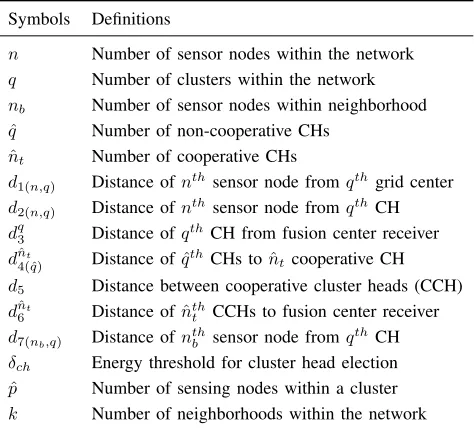
neighborhoods and the selection of cooperative sensor nodes for reporting to fusion center are made locally within the respective clusters throughout the network. Such distributive decision making ability facilitate the proposed UDCS frame-work to be energy efficient, as this reduces the amount of information to be broadcasted or transmitted wirelessly to represent an event. The list of key symbols used in this paper along with their definition is given in Table 1.
TABLE 1.Symbols and their definitions.
A. TIME-DRIVEN SENSING
A distributed cluster head selection scheme is proposed such that all the sensor nodes that can serve the role with minimum energy consumption have a chance to become cluster heads. It is expected that all the sensor nodes will broadcast their location to their respective cluster heads and cluster heads will broadcast this information within the network. Initially all the sensor nodes are expected to calculate their distance from the center of their grids. Then each sensor node is expected to be ranked based on its respective distance from the center of the cluster. The sensor node which is nearest to the center of the grid has the highest priority to become cluster head. A threshold energyδchis carefully defined such that if
the energy of a cluster head falls belowδch, the role of cluster
head is expected to be transferred to the second highest rank node. Once all the cluster heads are elected, the remaining sensor nodes find the nearest cluster heads and join them irrespective of their initial cluster assignment. The election of cluster heads and the formation of new clusters is explained below.
Let F(λ1
x, λ1y, λ2x, λ2y) represents the Euclidean distance
function which is defined as:
F(λ1x, λ1y, λ2x, λ2y)=
q
(λ1
x−λ2x)2+(λ1y−λ2y)2 (8)
center of their respective grids by using the function presented in (8) and expressed as:
d1=F(cx,cy,sx,sy) (9)
where
F(cx,cy,sx,sy)=F(λ1x =cx, λ1y =cy, λ2x =sx, λ2y =sy)
(10)
(cjx,cjy) are the coordinates of center of grids while
j= {1,2, . . . ,q}and (six,siy) are the coordinates of the sensor nodes where i = {1,2, . . . ,pj}. Consider S(j,i) denotes a
sensor node andpdenotes the maximum number of sensor nodes belonging to a particular grid given byp =max{pj |
j=1,2, . . . ,q}. LetQis a matrix of all the sensor nodes in the network which is defined as:
Q=
S(1,1) S(1,2) . . . S(1,p)
S(2,1) S(2,2) . . . S(2,p)
... ... ... ... S(q,1) S(q,2) . . . S(q,p)
(11)
where each row of matrixQrepresents the sensor nodes in each grid. Although the number of sensor nodes in each grid are not same but for the sake of mathematical representa-tionQis defined as a matrix. ConsiderS(j,i)is assigned with
a value to classify the existence of a sensor node which is defined as:
S(j,i)=
(
1, ifi≤pj
−1, ifi>pj
(12)
where 1 represents the existence of a sensor node and −1 represents the non-existence of a sensor node. LetD1is a
matrix of dimensions (q×p) which presents the distance of all the sensor nodes from the center of their grids and expressed as:
D1=
d1(1,1) d1(1,2) . . . d1(1,p)
d1(2,1) d1(2,2) . . . d1(2,p)
... ... ... ... d1(q,1) d1(q,2) . . . d1(q,p)
(13)
where each row of matrixD1represents the distance of sensor
nodes from their grid center. Letd1(q)presents the distance of
the sensor nodes from the center ofqthgrid which is expressed asd1(q) = {d1(q,1),d1(q,2), . . . ,d1(q,p)}. All the sensor nodes
are characterized as either normal nodes or cluster head nodes. Letξqconstitutes the information of the sensor node
which is at a minimum transmission distance from the qth grid center and can be defined as ξq = min(abs(d1(q)\ψ)).
Where ‘‘\’’ represents the difference between two sets. Con-sider, initially ψ = ∅ and it will keep the record of the sensor nodes that are elected as cluster heads throughout the lifetime of the network. Let pth sensor node is at a mini-mum transmission distance from the qth grid center which is denoted asd1(q,p) and defined asd1(q,p)\ψ = {d1(q,p) ∈
d1(q)|d1(q,p) ∈/ ψ}. In addition to minimum transmission
distance requirement, the energy of the candidate sensor node is compulsory to be greater than the thresholdδch. Once a
sensor node is designated as a cluster head, it is assigned with ς = 1 which shows its status as cluster head. This process iterates until allqcluster heads are defined and updateψ=ξ in each iteration. LetQsis a matrix of dimensions (q×p) and
presents the status of the sensor nodes which is defined as:
Qs(i,j)=
(
Cluster Head (CH), ifς=1
Normal Node (N), otherwise (14)
LetQchis a set of all the cluster heads in the network which
is defined as:
Qch= {Sjch|j=1,2, . . . ,q} (15)
whereqis the total number of cluster heads andSjchdenotes the cluster head fromjth cluster. All the sensor nodes with status N are expected to join the cluster head which is at min-imum transmission distance. LetD2contains the distances of
all the normal sensor nodes with theqnumber of cluster heads which is defined as:
D2=
d2(1,1) d2(1,2) . . . d2(1,q)
d2(2,1) d2(2,2) . . . d2(2,q)
... ... ... ... d2(n,1) d2(n,2) . . . d2(n,q)
(16)
whereD2is a matrix of dimensions (n×q) andd2is calculated
by using the function presented in (8) and expressed as:
d2=F(chx,chy,sx,sy) (17)
where
F(chx,chy,sx,sy)=F(λ1x =chx, λ1y=chy,
λ2
x =sx, λ2y =sy) (18)
(chjx,chjy) are the coordinates of the cluster heads while
j = {1,2, . . . ,q} and (s˘ix,s˘iy) are the coordinates of the sensor nodes where˘i = {1,2, . . . ,n}. Letd˘i
2is the˘ith row
ofD2which provides the transmission distance information
of˘ith sensor node fromq number of cluster heads. The˘ith sensor node is expected to join the cluster head which is at minimum transmission distance that is defined asmin{d˘i
2}.
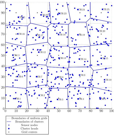
New boundaries of the clusters are defined as shown in Fig. 2. The proposed dynamic clustering scheme is summarized in Algorithm 1.
LetQˆj represents a set of sensor nodes in thejth cluster
which is defined as:
ˆ Qj= {S
j
i |i=1,2, . . . ,pˆj} (19)
AndQˆ is the set of all the clusters which is expressed as: ˆ
FIGURE 2. Implementation of dynamic cluster formation scheme within WSN.
quickly than non-cluster head sensor nodes. As the proposed dynamic clustering scheme is expected to rotate the cluster head role among all sensor nodes while minimizing the fre-quency of re-clustering, it is important to defineδchcarefully.
1) HARD THRESHOLD
It is defined as a function of residual energy in the clus-ter heads. Let 9 = {ψ1, ψ2, . . . , ψn¨}, where9 represents
the range of energy within a sensor node i.e. 9 ∈ [0,1]. Therefore the task for system design engineer is to find the optimum value from 9 to defineδchwhich requires
exten-sive simulation experiments. As the distribution of sensor nodes is expected to be random in most of the applications, dynamic clustering is required to be implemented to adapt with variable conditions within the network. Consequently, the criteria to find optimum threshold might change through-out the lifetime of the network that can lead to erroneous decisions on the selection ofδch, hence can cause unbalanced
energy consumption within the network. To overcome these limitations with aforementioned threshold selection method, a soft decision based threshold selection method is defined as follows.
2) SOFT THRESHOLD
It is defined based on an iterative method that compute k¨ number of optimum threshold values from 9, which are denoted asδch1, δch2, . . . , δchk¨ and defined as:
δkˆ
ch=
|ψ1−ψn¨|
0kˆ where
ˆ
k= {1,2, . . . ,k¨} (21)
Algorithm 1Proposed Dynamic Clustering Scheme
Require:
The number of sensor nodesnwithin the network, their coordinates (x˘i,y˘i)| ˘i=1,2, . . . ,nof each sensor node,
their energy which is denoted asS˘E
i , the coordinates of
the center of each grid (xj,yj) | j = 1,2, . . . ,q and
cluster head selection threshold energyδch
Ensure:
S(ch.) ←min{d1}andS˘iE≥δch
1: D1←∅,d1←∅
2: P1←∅,p1←∅
3: Qs←∅
4: forj←1toqdo 5: for˘i←1tondo
6: d1(˘i)←d1whered1is calculated from (9)
7: end for
8: d1 ← Sort{d1}, (Sort in ascending order and save
their respective indices inp1) 9: D1(j)←d1
10: P1(j)←p1
11: end for
12: τ ←0
13: forj←1toqdo 14: for˘i←1tondo
15: Q1(j,˘i)←Mapping of sensor nodes based onD1
andP1
16: ifSE˘
(.)≥δch&τ =0then
17: Qs ← Update the status of S(j,ˆi) as Cluster
Head (CH) or Normal Node (N)
18: τ ←1
19: end if
20: end for
21: end for
22: D2←∅,d2←∅
23: forj←1toqdo 24: for˘i←1tondo
25: d2(˘i) ← d2whered2is calculated from (17) &
(18)
26: end for
27: D2(j)←d2
28: end for
29: for˘i←1tondo
30: Qch(˘i)←min{D2(1:q,˘i)}
31: Assign the task of cluster head to the sensor nodes in
Qch
32: end for
33: return Qch
consumption is balanced through out the network at the cost of higher rate of re-clustering than would have with hard threshold.
B. EVENT-TRIGGERED SENSING
The selection of a group of sensor nodes, in response to an incident is one of the core elements of the proposed optimiza-tion process. Hence, this secoptimiza-tion describes the set out criteria of such incident triggered dynamic grouping schemes, such as neighborhood. One of the main tasks of sensor nodes is to monitor, detect and collect various significant occurrences of events within WSNs. The occurrence of the behavioral change that sensor nodes are expected to detect is called an event. Let there are k number of events occurred within a cluster at time instantt. It is assumed that the location of the events are implicitly deterministic. The trend of the sensing parameters and the knowledge of that trends at the cluster heads make the location of events implicitly deterministic. Consider, the coordinates of the location of events are denoted as (efxˆ,e
ˆ
f
y), whereex andey denotes the coordinates of the
location of an event andfˆ = {1,2, . . . ,k}. A neighborhood consists of a group of sensor nodes which are selected based on certain criterion i.e. distance from the location of an event, sensing capability etc. are expected to take part in the detection of the events. All the sensor nodes within a neighborhood are expected to cooperate with each other. For the sake of simplicity, it is assumed that each neighborhood at time instanttwill consist ofnbnumber of sensor nodes where
nbvaries from neighborhood to neighborhood. Let there are
k number of neighborhoods formed by the occurrence of k number of events at time instant t. The total number of sensor nodes involved to formkthnumber of neighborhood is denoted asNk
e and is defined as:
Nek |t= {skˆe| ˆe=1,2, . . . ,nkb} (22) It is assumed that all the neighborhoods formed at time instant twill not overlap with each other which is defined as:
Ne1|t ∩ Ne2|t ∩ · · · ∩Nek |t ∈Ø (23) Depending on the depth of the event, the set of sensor nodes involved to form a neighborhood for an event detection at time instantt can be same or can be different from an event that will be detected at time instantt+1, even both events occur at same location. With the aim of achieving energy conservation, the sensor nodes are expected to form a neigh-borhood by fulfilling the following criteria:
1) CRITERION 1
It is defined based on the Euclidean distance of the sensor nodes from the location of an event. LetNefˆis thefˆth
neigh-borhood which is defined as:
Nˆf e =
Sefˆˆ ∈S(.), ifdˆ
ˆ
f
ˆ
e ≤δd
Sfˆˆ
e ∈/S(.), otherwise
(24)
wheredˆˆefˆdenotes the distance ofeˆthsensor node fromfˆth event andδd is the threshold distance defined by the fusion
center receiver.
2) CRITERION 2
This criterion is based on the sensitivity thresholdδsdefined
by the fusion center receiver. Each sensor node is expected to be a part of the neighborhood if it can sense the event
with the predefined sensitivity thresholdδs. LetN
ˆ
f
e is thefˆth
neighborhood which is defined as:
Nefˆ =
Sˆefˆ∈S(.), ifν
ˆ
f
ˆ
e ≥δs
Sˆefˆ∈/S(.), otherwise
(25)
whereνˆefˆ denotes the sensitivity range ofˆeth sensor node fromfˆthevent.
3) CRITERION 3
This criterion is unification of both aforementioned criteria. On the occurrence of an event, the sensor nodes are selected to form thekthneighborhood based on the criterion which is defined as:
Nfˆ e =
Sefˆˆ ∈S(.), ifdˆ
ˆ
f
ˆ
e ≤δd∩ν
ˆ
f
ˆ
e ≥δs
Sefˆˆ ∈/S(.), otherwise
(26)
The detailed procedure of neighborhood formation is explained in Algorithm 2.
C. CQI BASED ADAPTIVE COOPERATIVE COMMUNICATION
A cooperation based transmission scheme is proposed that is expected to optimize network communication and trans-mission reliability by dynamically selecting the degree of cooperation among sensor nodes. In order to enable ample determination on the selection of suitable degree of coopera-tion among sensor nodes, an estimate of transmission quality for given channel conditions is required which is usually mea-sured from frame error probability. A CQI model presented in [30] is used in this paper, which is defined based on a measure that maps frame error probability. It is expected that CQI based adaptation will provide robustness against signal distortions and interference caused by propagation and chan-nel conditions respectively. Also, it will provide adequate decision on the degree of cooperation in order to optimize resource utilization while maintaining demanded quality of service. The measure of CQI can be calculated as:
CQI=f(E[(˜ 3−µ)2]) (27)
whereE denotes the expectation value and CQI can be sim-˜ plified as:
CQI= 1 nt
nt
X
ˆ
i=1
|3ˆ
i−µ|
Algorithm 2Proposed Neighborhood Formation Scheme
Require:
The number of sensor nodesn, the coordinates (six,siy)| i = 1,2, . . . ,n of each sensor node, Total number of events k, the coordinates (efxˆ,e
ˆ
f
y) | fˆ = 1,2, . . . ,k
of each event, desired neighborhood selection criteria parameterαandβ, Optimum distance thresholdδdand
Optimum sensitivity level thresholdδs.
Ensure: dˆfˆ
ˆ
e ≤δdandν
ˆ
f
ˆ
e, wheredˆ is the distance andsˆis the
sensitivity level ofeˆthsensor node fromfˆthevent.
1: Dn ←∅,dn←∅
2: Pn←∅,pn←∅
3: sn ←∅
4: if(α=1)∪(α∩β =1)then 5: forfˆ←1tokdo
6: foreˆ←1tondo
7: dn(e)ˆ ← ˆd
ˆ
f
ˆ
e
8: end for
9: Sort{dn}in ascending order and save the indices
inpn
10: Dn(fˆ)←dn
11: Pn(fˆ)←pn
12: end for
13: forfˆ←1tokdo
14: foreˆ←1tondo
15: if Dn(ˆe,fˆ)≤δdthen
16: Assign the corresponding sensor nodes to
Nefˆ
17: end if
18: end for
19: end for
20: end if
21: if(β=1)∪(α∩β=1)then 22: forfˆ←1tokdo
23: foreˆ←1tondo
24: Sefˆˆ ≥δs(fˆ)
25: end for
26: Assign corresponding sensor nodes toNefˆ
27: end for
28: end if
29: returnNk
e
where
µ= 1 nr
nr
X
ˆj=1
λˆj (29)
where3is a set of eigen vectors channel coefficient matrixH
of dimension (nr×1) which is defined as:
3= {λˆ
j| ˆj=1,2, . . . ,nr} (30)
where λ(·) represents the eigen values of channel
coeffi-cients. The degree of cooperation is to be selected based on classification of signal propagation conditions that can be
acquired from CQI which is indexed from 1 to the required degree of considered cooperation. The higher index refers to the requirement of higher degree of cooperation in order to maintain the required quality of service.
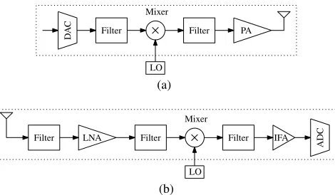
FIGURE 3. (a) Transmitter circuit blocks, (b) Receiver circuit blocks.
V. NETWORK LIFETIME MODEL
Network lifetime can be defined as the time span over which the network operates effectively. Several WSNs lifetime def-initions have been introduced in the literature e.g. network connectivity is used to define WSN lifetime. But most com-monly used WSN lifetime definition is based on the per-centage of alive nodes or dead nodes in the network, which reflects the quality of network coverage and connectivity as discussed in [31]. In this section, a network lifetime model is presented based on energy model described in [23]. It is assumed that each cluster consists of pˆ number of sensor nodes. Each sensor node is expected to senseLbits and trans-mits it to the respective cluster head node. As sensor nodes in a cluster are closely spaced, the sensed data is expected to be correlated. So, cluster heads are expected to aggregate the received data. All the sensor nodes are expected to be equipped with one transceiver. The transmitter and receiver blocks used in this model are shown in Fig. 3(a) and Fig. 3(b) respectively. For a fixed rate system, the total energy per bit is denoted asEbitand defined as:
Ebit =
PPA+Pc
Rb
(31)
wherePPAis the power consumption of power amplifier,Pc
is the power consumption at transceiver circuitry andRbis
the bit rate.PPAis expressed as:
PPA=(1+α)Pout (32)
whereα=(ξ/η)−1 withξis the peak to average ratio andη is the drain efficiency of the radio frequency power amplifier. Pout represents the transmit power which can be calculated
based on link budget relationship, particularly when the chan-nel experiences only a square law path loss as described in [32] and expressed as:
Pout = ¯EbRb
(4πd)2
GtGrλ2
where E¯
b represents the required energy per bit at the
receiver for a given bit error rate requirement,Rbrepresents
the bit rate,drepresents the transmission distance,GtandGr
represent the transmitter and receiver antenna gains respec-tively,λrepresents the carrier wavelength,Nf represents the
receiver noise figure which is defined asNf =Nr/No, where
Nr is the power spectral density (PSD) of the total effective
noise at receiver input and No is the single sided thermal
noise PSD at room temperature, andMl represents the link
margin for compensating the hardware processing variations and additive background noise. Let
P =(1+α)E¯bRb
(4π)2
GtGrλ2
MlNf (34)
Therefore, (32) can be represented as:
PPA=Pd2 (35)
The power consumption of transceiver circuitry is further divided into power consumption at transmitter and receiver circuitry which isPc=Pctx+Pcrx. WherePctx is defined as:
Pctx =PDAC+Pfilt+Pmix (36)
wherePDAC,PfiltandPmixrepresents the power consumption
at digital to analogue converter, filter and mixer respectively. Pcrx is defined as:
Pcrx =PLNA+Pmix+Pfilt+PIFA+PADC (37)
wherePLNA,PIFAandPADCrepresents the power
consump-tion at low noise amplifier, intermediate frequency amplifier and analogue to digital converter respectively.
A. LOCAL COMMUNICATION
The communication between the sensor nodes and their respective cluster heads is referred to as local communication.
1) ENERGY CONSUMPTION OF INTRA-CLUSTER COMMUNICATION
The energy required by the sensor nodes to communicate with their cluster heads is denoted asEIntraCand defined as.
EIntraC = q
X
j=1
ˆ p X ˘
i=1
LEj
s(˘i)+LE
j chpˆ
(38)
whereEchq represents the energy required by theqthcluster head to receive one bit data from itspˆth sensor node which can be defined as:
Echq = EdaPcrx
Rb
(39)
whereEdarepresents the energy required to aggregate one bit.
LetEj
s(˘i)forpˆ
thsensor node ofqthcluster is denoted asEq s(pˆ)
and defined as:
Eq
s(pˆ)=
1 Rb
P(d2(qˆ
p)) 2+P
ctx
(40)
whered2(qpˆ)represents the distance ofpˆthsensor node from qth cluster head. All the sensor nodes within the network are expected to forward their sensing data to their respective cluster heads. Once a cluster head receives data from all of its member sensor nodes within the cluster, it performs data aggregation. As the sensor nodes within a cluster are closely spaced, their sensing data is correlated. Therefore, data aggregation at the ratio of 10:1 is assumed and the sensing data after aggregation is denoted asLda.
B. GLOBAL COMMUNICATION
Two types of global communication approaches considered in this paper which are defined as:
1) DIRECT COMMUNICATION BETWEEN CLUSTER HEADS AND FUSION CENTER RECEIVER
The energy required for direct communication between clus-ter heads and fusion cenclus-ter receiver is denoted as ED and
defined as:
ED= q
X
j=1
LdaEshj (41)
whereEDis the energy required byqcluster heads to forward
the sensing data to the fusion center in one round andEshj is the energy consumed byjthcluster head to forward one bit of sensing data to the fusion center e.g. the energy required byqthcluster head is defined as:
Eshq = 1 Rb
P(d3q)2Pctx
(42)
whered3qis the transmission distance ofqthcluster head from fusion center. The total energy required by the network for one round can be defined as:
Eor.sh=EIntraC +ESH (43)
By substituting (38) and (41), (43) can be defined as:
Eor.sh= q
X
j=1
ˆ p X ˘
i=1
LEj
s(˘i)+LE
j chpˆ
+ q X
j=1
LdaEshj
(44)
For simplified solution it is assumed that the transmission distance of the sensor nodes from its cluster heads isd2and
the transmission distance from cluster heads to fusion center receiver isd3. Therefore, (43) can be further simplified by
substituting (39), (40) and (42) which can be represented as:
Eor.sh =
Lqpˆ Rb
P(d2)2+Pctx +EdaPcrx
+qLda Rb
P(d3)2+Pctx
(45)
Eor.sh =
q Rb
(1+α)E¯
bRb
(4π)2MlNf
GtGrλ2
ˆ
pLd22+Ldad32
+ (Lpˆ+Lda)Pctx +EdaLpPˆ crx
2) MULTI-HOP COMMUNICATION BETWEEN CLUSTER HEADS AND FUSION CENTER RECEIVER
a: SELECTION OF COOPERATIVE CLUSTER HEADS
As mentioned in previous section d3 represents the
trans-mission distance of all the cluster heads from fusion center receiver which is defined asd3 = {d31,d32, . . . ,d
ˆ
p
3}andξ
ˆ
nt
represents the distance ofnˆtht cooperative cluster heads which is defined as:
ξnˆt =min(abs(d
3\ω)) (47)
where Initiallyω= ∅anddnˆt
3 \ωis defined as:
dnˆt
3 \ω= {d
ˆ
nt 3 ∈d3|d
ˆ
nt
3 ∈/ω} (48)
The sensor nodes presented byξk are classified as coopera-tive cluster head if their energy is greater than the threshold δcoop, wherek= {1,2, . . . ,nˆt}. Oncenˆtnumber of
coopera-tive cluster heads are selected, sensor nodes status matrixQs
is updated. This process is summarized in Algorithm 3:
Algorithm 3Cooperative Sensor Nodes Selection Scheme
Require:
The q number of cluster headsQch, their transmission
distances from the sink node which is denoted withd3,
cooperative sensor node selection threshold energy value δcoopand the sensor nodes status matrixQs
Ensure:
S(coop.) ←min{d3}andE˘jch≥δcoop
1: dˆ3←∅,Qˆch←∅
2: Qc.coop←∅,Qˆc.coop←∅
3: dˆ3←sort{d3}
4: Qˆch←sort{Qch}corresponding todˆ3 5: forj←1toqdo
6: Sc.coop←Sjch
7: ifScoopE ≥δcoopthen 8: Qc.coop(j)←Sc.coop
9: end if
10: end for
11: Qˆc.coop=Qc.coop(Qc.coop6=0)
12: fork←1tonˆtdo
13: Qcoop(k)←Qc.coop(k)
14: end for
15: return
b: ENERGY CONSUMPTION OF INTER-CLUSTER COMMUNICATION
The energy required by the cluster heads to communicate with each other is denoted asEInterC. Letnˆtnumber of cluster head
nodes are selected to cooperate and communicate with the fusion center receiver, then the remainingq− ˆnt number of
sensor nodes are denoted asqˆ =q− ˆnt.
EInterC =
ˆ
q
X
ˆ
j=1
LdaEnj.coop+q1LdaEcoop (49)
whereEcooprepresents the energy required by the cooperative
cluster head node to receive one bit data from the non-cooperative cluster head nodes which is defined asEcoop =
Pcrx/Rb. ConsiderE
ˆ
q
n.coop represents the energy required by
theqˆthnon-cooperative cluster head node to transmit one bit of data to the cooperative cluster heads, which is defined as:
Enqˆ.coop= 1 Rb
P(dq1 4 )
2+P
ctx
(50)
3) ENERGY CONSUMPTION OF LONG-HAUL COMMUNICATION
The nˆt number of selected cooperative cluster head nodes
are expected to collaborate and act as virtual MIMO antenna to transmit the sensing data to the fusion center receiver. The energy consumed in this process can be categorized into ELh−SM if cooperation among the transmitting nodes
is exploited to achieve spatial multiplexing andELh−DIV if
transmission diversity is required which are described as:
a: CASE I
ELh−SM =
ˆ
nt−1
X
k=1
qLda
ˆ nt
Ecolk .+
ˆ
nt
X
k=1
qLda
ˆ nt
Elhk (51)
b: CASE II
ELh−DIV =
ˆ
nt−1
X
k=1
qLdaEcolk .+
ˆ
nt
X
k=1
qLdaElhk (52)
where
Enˆt
col.=
1 Rb
P(dnˆt 5 )
2+P
ctx+Pcrx
(53)
wherednˆt
5 is the distance of thenˆtht cooperative cluster head
from other cooperative cluster heads.
Enˆt
lh =
1 Rb
P(dnˆt 6)
2+P
ctx +Psyn
. (54)
whered6is the distance of the cooperative cluster head from
fusion center andPsynrepresents the power required to
syn-chronise the transmitting data from multiple nodes. LetEo.r
represents the total energy requires to transmitLda bits. It is
assumed that one round is the transmission of data from all the sensor nodes to the fusion center.Eo.r is defined as:
Eo.r =EIntraC+EInterC+ELh (55)
Therefore, (55) can be simplified as (56), as shown at the top of the next page. Asqˆ nt, so lets assumeq ≈ ˆq, so
it can further be simplified into (57) and (58), as shown at the top of the next page, where (58) provides a generalized equation for energy consumption of time-driven and event-driven scenario. Based on the type of sensing, the parameters in (58) are obtained as follows:
(
Q=q,N = ˆp,D=d2 Time-driven
Eo.r = q
X
j=1
ˆ
p
X
i=1
LEj
s(ˇi)+LE
j chpˆj
+ ˆ q X
j=1
LdaEnj.coop+ ˆqLdaEcoop
+
ˆ
nt−1
X
k=1
qLda
ˆ nt
Ecolk .+
ˆ
nt
X
k=1
qLda
ˆ nt
Elhk
(56)
= Lqpˆ Rb
P(d2)2+Pctx +EdaPcrx
+qLˆ da Rb
P(d4)2+Pctx +Pcrx
+qLda Rb
P(d5)2+Pctx +Pcrx
+qLda Rb
P(d6)2+Pctx +Psyn
(57)
= Q Rb
(1+α)E¯
bRb
(4π)2 GtGrλ2
MlNf
NLD2+L
da(d42+d52+d62)
+(NL+3Lda)Pctx +(NLEda+2Lda)Pcrx +LdaPsyn
(58)
C. EVENT-DRIVEN SENSING
The energy required by the sensor nodes to transmit event data to cluster head is denoted as EIntraNH and defined
as:
EIntraNH = k
X
ˆ
m=1
ˆ
nmbˆ
X
ˆ
l=1
LEsmˆˆ
l +LE
ˆ
m chnˆb
(59)
whereEsmˆˆ
l fornˆ th
b sensor node ofk
thneighborhood is denoted
asEsknˆ
b and defined as:
Esknˆ
b =
1
Rb
P(d7(knˆb))2+Pctx
(60)
whered7(kˆ
nb)represents the distance of
ˆ
nthb sensor node from kthneighborhood head.Echk represents the energy required by thekthcluster head to receive event data fromnbsensor nodes
which is defined as:
Echk = EdaPcrx Rb
(61)
The cluster head receives the sensing data from all the sensor nodes within the neighborhood, it performs data processing locally, detects the event and transmits the decision to fusion center receiver through cooperative nodes. This approach will accelerate the decision making process by making cluster heads self reliant and also minimize the number of trans-missions to fusion center receiver that results in energy conservation.
VI. PERFORMANCE ANALYSIS
This section demonstrates the performance analysis of the proposed dynamic and cooperative clustering and neighbor-hood formation scheme for WSNs. The proposed framework is expected to facilitate the applications that consider either time-driven sensing, event-driven sensing or both denoted as hybrid sensing. To demonstrate the effectiveness of the pro-posed schemes, a WSN model is simulated. Moreover, all the proposed schemes are analyzed in terms of network lifetime i.e. number of alive nodes and residual energy. To enhance the
transmission reliability, the dynamic behavior among sensor nodes is adopted to adapt dynamic channel conditions which is expected to provide a tradeoff between energy efficiency and transmission reliability.
A WSN model is simulated with a sensing area of (100×100)m2withn=100 sensor nodes with initial energy Eo=1J which are randomly distributed within the network.
Furthermore, the simulation environment is composed of a fusion center receiver that is located at a distance of 50mfrom the nearest boundary of the sensing region. After deployment, the network is expected to perform dynamic clustering to divide the sensor nodes into clusters. Once settled, all the sensor nodes within the network are expected to sense the environment and transmit sensed data to their respective clus-ter heads which are responsible to perform data correlation and relay it to fusion center receiver through cooperative nodes. The process from re-clustering to data transmission to fusion center receiver is defined as one round. At each round, the cluster heads are expected to evaluate themselves and withdraw from cluster head role if they do not fulfil cluster head role criteria, and trigger re-clustering process. Table 2 presents the parameter values considered in the simulations as described in [33].
A. PERFORMANCE ANALYSIS OF PROPOSED DYNAMIC CLUSTERING SCHEME WITH SOFT THRESHOLD AND HARD THRESHOLD
TABLE 2. Simulation parameters and their values.
FIGURE 4. Performance analysis of the proposed dynamic clustering scheme with soft threshold and hard threshold for number of alive nodesNAand roundsR.
B. PERFORMANCE COMPARISON OF PROPOSED DYNAMIC CLUSTERING SCHEME WITH EXISTING CLUSTERING SCHEMES
This section demonstrates the performance evaluation of the proposed dynamic clustering scheme with existing clustering schemes in the literature. In order to perform fair comparison, three simulation platforms have been simulated in this section denoted as model 1, model 2 and model 3 for performance comparison with homogeneous, heterogeneous and coopera-tive WSNs respeccoopera-tively which are described as:
1) MODEL 1
It provides a platform to compare the performance of the proposed dynamic clustering scheme with LEACH proposed
by Heinzelmanet al.in [6]. It is assumed that all the sensor nodes are homogeneous and cluster heads are responsible for relaying data to fusion center receiver. It is observed from Fig. 5 that the first node died (FND) for proposed dynamic clustering scheme at 1370 rounds while the FND for LEACH at 903 rounds. Also, the half nodes died (HND) for the proposed scheme and for LEACH at 2334 and 1198 rounds respectively. Moreover, the last node died (LND) at 3415 and 1862 rounds for the proposed scheme and existing scheme LEACH respectively. Hence, the proposed scheme enhances the lifetime of sensor nodes by 51%, 94% and 83% rounds for number of alive nodes 100%, 50% and 1% respectively.
FIGURE 5. Performance analysis comparison of the proposed scheme with LEACH [6] considering homogeneous network for number of alive nodesNAand roundsR.
2) MODEL 2
To evaluate the performance of the proposed dynamic clus-tering scheme for heterogeneous WSNs, model 2(a) and 2(b) are simulated for two level and three level heterogeneous sensor nodes respectively. The performance of the proposed dynamic clustering scheme is compared with the existing clustering scheme for heterogeneous WSNs i.e. DEEC [9], DDEEC [34] with two level heterogeneity and EDEEC [35] and EDDEC [36] with three level heterogeneity as presented in Fig. 6 and Fig. 7 respectively. In model 2(a) the WSN is comprised of sensor nodes which are categorized as normal sensor nodes and advanced sensor nodes based on their ini-tial energy where the number of normal sensor nodes and advanced sensor nodes n×(1 −m) and n ×m. While in model 2(b), sensor nodes are categorized as normal sensor nodes, advanced sensor nodes and super sensor nodes, where the number of normal sensor nodes, advanced sensor nodes and super sensor nodes are calculated as n × (1 − m), n×m×(1−mo) and n ×m×mo respectively; where m
andmoare assumed as 0.3. The advanced sensor nodes and
super sensor nodes energy can be calculated as (1+a)Eo
and (1 + b)Eo respectively, where a and b are assumed
FIGURE 6. Performance analysis comparison of the proposed scheme with DEEC [9] and DDEEC [34] considering two level of heterogeneous network for number of alive nodesNAand roundsR.
FIGURE 7. Performance analysis comparison of the proposed scheme with EDEEC [35] and EDDEEC [36] considering three level of
heterogeneous network for number of alive nodesNAand roundsR.
4351 rounds respectively. While the FND for DEEC and DDEEC at 936 and 2013 respectively, the HND at 2145 and 2232 rounds respectively, and the LND at 3531 and 3770 rounds respectively. Hence, the proposed scheme quantifies the network lifetime by 23.2% and 15.4% rounds as compared to DEEC and DDEEC respectively. Also, Fig. 7 validates that the FND,HND and LND for the proposed scheme at 2158, 3391 and 4635 respectively. While the FND for EDEEC and EDDEEC at 1813 and 1761 respectively, the HND at 2401 and 2492 rounds respectively, and the LND at 4157 and 4520 rounds respectively. Therefore, the proposed scheme enhance the network lifetime by 11.5% and 2.6% as compared to EDEEC and EDDEEC respectively.
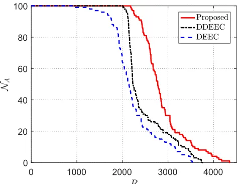
3) MODEL 3
It provides the network lifetime analysis with coopera-tion among sensor nodes while transmitting data to fusion
FIGURE 8. Performance analysis of the proposed scheme for cooperative communication realizing virtual MIMO transmission and exploiting diversity for number of alive nodesNAand roundsR.
center receiver. The simulation parameters are considered as provided by authors in [37]. The simulation results pre-sented in Fig. 8 demonstrates that the FND, HND and LND for the proposed scheme at 601, 2101 and 2801 rounds respectively for (nt,nr) = 2. While for the COOP-LEACH
presented in [37] the FND, HND and LND at 890, 3165 and 4643 rounds respectively for (nt,nr) = 2. Similarly, the
LND for the proposed scheme and the COOP-LEACH at 4185 and 2251 rounds respectively when (nt,nr) = 3, at 3756
and 1801 rounds respectively when (nt,nr) = 4, and at 3145
and 1551 rounds respectively when (nt,nr) = 5. Hence, the
proposed scheme increases the network lifetime by 50.6%, 35%, 40.5% and 49% with (nt,nr) = 2, 3, 4 and 5 respectively
for 50% alive nodes as compared to COOP-LEACH; while cooperation among sensor nodes is exploiting diversity to achieve transmission reliability.
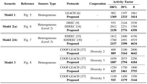
A detailed comparison analysis of the proposed dynamic clustering scheme with the aforementioned existing schemes is presented in Table 3. It is validated from the Table 3 that the proposed scheme outperforms the existing schemes.
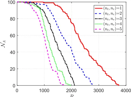
C. PERFORMANCE ANALYSIS OF PROPOSED UNIVERSAL FRAMEWORK
TABLE 3. Comparison of the proposed dynamic clustering scheme with existing schemes for homogeneous and heterogeneous WSNs.
FIGURE 9. Performance analysis of the proposed scheme for time-driven applications for number of alive nodesNAand roundsR.
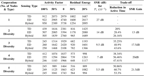
It is found that by increasing the number of cooperative sensor nodes, the proposed universal framework provides a tradeoff between the network lifetime and data transmission reliability. Also, exploiting diversity increases the signal to noise ratio (SNR) gain of 13 dB, 17.5 dB, 20 dB and 21.5 dB with the decrease in network lifetime by 20%, 35.2%, 38.4% and 50.8% for degree of cooperation 2, 3, 4 and 5 respectively to achieve 10−3probability of errorPeas compared to
con-ventional transmission. A detailed performance comparison of the proposed scheme is described in Table 4.
FIGURE 10. Performance analysis of the proposed scheme for time-driven applications for average residual energyREand roundsR.
D. PERFORMANCE ANALYSIS OF THE PROPOSED UNIVERSAL FRAMEWORK WITH CQI
FIGURE 11. Performance analysis of the proposed scheme for event-driven applications for number of alive nodesNAand roundsR.
FIGURE 12. Performance analysis of the proposed scheme for
event-driven applications for average residual energyREand roundsR.
FIGURE 13. Performance analysis of the proposed scheme for hybrid applications for number of alive nodesNAand roundsR.
as stated in [38].
Pe=
h
1 2(1−µ)
iLLX−1 ˆ
l=0
L−1+ ˆl
ˆ l
h
1 2(1+µ)
iˆl
(62)
FIGURE 14. Performance analysis of the proposed scheme for hybrid applications for average residual energyREand roundsR.
FIGURE 15. Probability of error for conventional transmission with one transmit-receive antenna pair and cooperative transmission for degree of diversity 2, 3, 4 and 5.
FIGURE 16.Probability of error for cooperative transmission with channel quality index (CQI) based adaptation for degree of diversity 2, 3, 4 and 5.
where µ = q γ
1+γ with average received SNR γ and L
TABLE 4. Performance analysis of the proposed universal framework for time-driven, event-driven and hybrid scenario within WSNs.
TABLE 5. Channel classification and degree of cooperation selection criterion.
FIGURE 17. Performance analysis of the proposed universal framework with channel quality index (CQI) based adaptation for number of alive nodesNAand roundsR.
cooperative nodes based on the signal propagation condi-tions to maintain required quality of service are presented in Fig. 16, Fig. 17 and Fig. 18. These simulation results
FIGURE 18. Performance analysis of the proposed universal framework with channel quality index (CQI) based adaptation for average residual energyREand roundsR.
TABLE 6. Performance analysis of the proposed universal framework with CQI based adaptation for network lifetime and detection reliability.
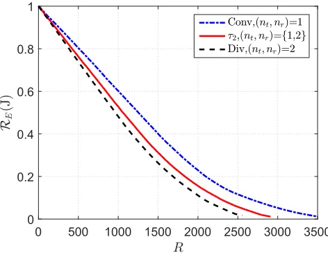
FIGURE 19. Performance comparison of the proposed universal framework with channel quality index (CQI) based adaptation (nt,nr) =
{1,2} represented by (τ2), conventional cooperative transmission
(nt,nr)=1 represented by (Conv) and virtual MIMO diversity for (nt,nr)
= 2 represented by (Div) for number of alive nodesNAand roundsR.
Let τ5 represents the set of transmit-receive antennas
{1,2,3,4,5},τ5−is min{τ5}andτ5+is max{τ5}. It is observed that the adaptive selection of number of cooperative nodes enhance detection reliability and network lifetime by 15.4% and achieve 20 dB SNR gain as compared to τ5− and τ5+ number of cooperative nodes. For τ4 = {1,2,3,4}, the
CQI based cooperative transmission for hybrid scheme can enhance network lifetime by 12.5% and achieve 17.5 dB SNR gain as compared toτ4+ andτ4− respectively. Performance comparison of hybrid scheme with adaptive transmission, conventional cooperative transmission (nt,nr)=1 and virtual
MIMO diversity for (nt,nr) = 2 are presented in Fig. 19
and Fig. 20. It is found that the dynamic property of the proposed framework provides a tradeoff between network lifetime and detection reliability. It is observed that proposed scheme enhance the network lifetime by 14% as compared to τ2+ with the cost of 3 dB SNR. Moreover, it achieve 5 dB SNR gain as compared to τ2− with the cost of 15.8% network lifetime. The decision on the selection of degree of cooperation is presented in Table 5 and a detailed comparison
FIGURE 20. Performance comparison of the proposed universal framework with channel quality index (CQI) based adaptation (nt,nr) = {1,2} represented by (τ2), conventional cooperative transmission
(nt,nr)=1 represented by (Conv) and virtual MIMO diversity for (nt,nr)=2 represented by (Div) for average residual energyREand roundsR.
of the proposed hybrid scheme with adaptive cooperative transmission is summarized in Table 6.
VII. CONCLUSION
![FIGURE 5. Performance analysis comparison of the proposed schemewith LEACH [6] considering homogeneous network for number of alivenodes NA and rounds R.](https://thumb-us.123doks.com/thumbv2/123dok_us/999154.1599697/13.576.298.534.221.396/performance-analysis-comparison-proposed-schemewith-considering-homogeneous-alivenodes.webp)