http://www.sciencepublishinggroup.com/j/jeee doi: 10.11648/j.jeee.20190706.15
ISSN: 2329-1613 (Print); ISSN: 2329-1605 (Online)
New Method for Zero Potential Non-stop Operation of
Distribution Network Based on Injection Current
Zhu Liang
1, 2, Wang Zhenyu
1, 2, *, Yang Qi
1, 2, *, Xu Li
1, 2, Guo Hao
1, 2, Pen Shasha
1, 21
Hunan transmission Maintenance Company, Changsha, China
2Live Inspection and Intelligent Operation Technology State Grid Corporation Laboratory, Changsha, China
Email address:
*
Corresponding author
To cite this article:
Zhu Liang, Wang Zhenyu, Yang Qi, Xu Li, Guo Hao, Pen Shasha. New Method for Zero Potential Non-stop Operation of Distribution Network Based on Injection Current. Journal of Electrical and Electronic Engineering. Vol. 7, No. 6, 2019, pp. 163-169.
doi: 10.11648/j.jeee.20190706.15
Received: November 4, 2019; Accepted: December 7, 2019; Published: December 12, 2019
Abstract:
In the case of live working in the distribution network, a live method of live working that satisfies the requirements for personal safety and power supply reliability needs to be studied, because of the serious safety accidents caused by misuse and weak safety awareness. Based on the zero potential characteristics of the operating point, a new method based on injection current for zero-potential uninterrupted operation in distribution network is proposed. The Floyd algorithm is used to calculate the shortest electrical distance from the live working point to the substation, and the capacitance value of the ground is measured by the resonant grounding system, and the current value injected further to the neutral point is calculated. By regulating the zero-sequence voltage, the neutral point voltage is equal to the difference between the operating phase line voltage drop and the operating phase power supply voltage, ensuring that the operating point voltage is zero. Finally, based on the PSCAD simulation software, the system model is established. The simulation verifies the feasibility of the proposed method by comparing the voltage curves of the working phase.Keywords:
Distribution Network, Voltage Control, Floyd Algorithm, Resonant Grounding System, Operating Device1. Introduction
With the rapid development of China's power grid and the continuous improvement of power supply reliability requirements [1], the research and standardization work of the live working technology has become a new development and breakthrough [2]. If the fault cannot be removed within a short time, it would affect the reliability of the power supply and the quality of the power supply [3-4]. Therefore, live working as an important means to improve power supply reliability and service quality has received increasing attention. It was of great practical significance for the study of the methods on distribution network protection [5-6].
In recent years, the research on live working in the distribution network has been rapidly developed in order to meet the diversification of the distribution network operation mode and grid structure. In the current study, there were two main ways of not stopping power: (1) Working directly on
technology of the operating point, this paper studies the zero-sequence current to control the phase voltage of the operating point to zero, and proposes a zero-potential non-blackout method. Finally, the feasibility of the proposed method is verified by simulation software PSCAD.
2. Zero-potential Non-blackout
Operation Method for Distribution
Network
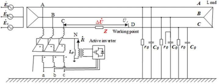
As shown in Figure 1, the current Iɺi is injected into the
neutral point through the grounding transformer, which causes the neutral point to ground voltage UɺN to shift. A, B, C three relative ground voltage changes, but the line voltage between
the phases is not affected. Since the general distribution network power supply and load are delta connection, the zero sequence voltage change does not affect the power supply and load, so the power supply and load are not affected by the C phase step-down, so the non-effective ground distribution system has a single-phase step-down line. The advantage of voltage symmetrical operation leads to feasibility of single-phase buck symmetrical operation.
In Figure 1, the C-phase line needs to be energized. Assume that the operating point voltage is Uɺf, the neutral
point voltage is UɺN, the line unit impedance is z, the voltage drop between the power bus and the operating point is ∆Uɺ , and the three-phase power supply voltage is respectivelyEɺA、EɺB、EɺC.
Figure 1. Working Point Zero Potential Control Principle Diagram.
The concentrated series impedance can be used as the equivalent impedance of the line, due to the lower voltage level and lower capacitance current in the distribution network of 35kV and below. When the working phase current
is
. c
I , ∆Uɺ can be obtained by Ohm's law:
. . C
U I Zl
∆ = (1)
Based on the KCL theorem and the KVL theorem, the neutral point voltage and the operating point voltage expression can be obtained as shown in equation (2).
. . . .
. . . .
0 0 0
=
( ) ( ) ( )
C
N d
i A N B N C N N L
U U E U
I E U Y E U Y E U U Y U Y
− + ∆
= + + + + + − ∆ +
(2)
Where,
. i
I is the current injected into the neutral point by the active inverter, Y0is earth admittance when the power grid is in normal operation, YL is ground admittance of arc suppression coil.
When Uɺf=0, the corresponding operating point potential
is zero. UɺN can be expressed as:
. .
.
0 0
3 i N
L
I U Y U
Y Y
+ ∆ =
+ (3)
Considering the formula (1)-(3) comprehensively, the expression of the injected current required by the zero-potential uninterruptible operation method of the distribution network can be calculated.
. . .
0 0
( )(3 )
i C C L C
I = −Eɺ +I zl Y +Y −I zlY (4)
3. Calculation Method of the Shortest
Electrical Distance from Live Working
Point to Substation
In the above method, it is necessary to know the voltage drop from the substation to the operating point∆Uɺ , and it is related to the line unit impedance z and the electrical distance
l
from the substation to the working point. The unit impedance of the line can be obtained by the line parameters and related measuring equipment. The electrical distancel
live working point of the distribution network to the substation is proposed.
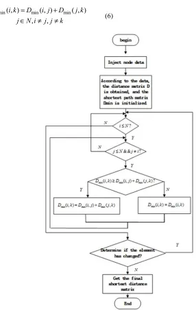
The method process is as follows:
1)The branch nodes of the line are numbered(1, 2,⋯, )n with the substation as the center, the total number of nodes is n, and the node set is N;
2)The distance matrix D is obtained by the adjacent distance between the nodes;
3)Define the shortest path matrix as Dmin, letDmin =D; 4)Determine whether (5) is true when seeking the shortest
path;
min( , ) min( , ) min( , )
, ,
D i k D i j D j k
j N i j j k
≥ +
∈ ≠ ≠
(5)
If equation (5) holds, then equation (6) satisfies the condition, otherwise equation (7) satisfies the condition.;
min( , ) min( , ) min( , )
, ,
D i k D i j D j k
j N i j j k
= +
∈ ≠ ≠
(6)
min( , ) min( , )
D i k =D i k (7)
Let j=1, 2,…, ,n i≠ j j, ≠k. Search all nodes in turn. If the elements in matrix Dmin have not changed during the search, Dmin is the final shortest path matrix. If an element changes, jump to step (4) until all elements are no longer Until there is a change;
5)Output matrix Dmin. The arbitrary element of the matrix is the shortest distance from branch node i to branch node j.
min( , )
D i j
i N
j N
∈
∈
(8)
The above steps are shown in Figure 2.
4. The Measurement Method of Resonant
Grounding Distribution Network
Capacitance
Accurate calculation of the injection current is used to achieve zero potential control at the operating point, and it is required to accurately measure the insulation parameters of the distribution network. Considering the influence of damping resistance on the measurement of the grounding parameters of the distribution network, a new method for measuring the capacitance of the grounding system to the ground is proposed, which can improve the accuracy of the capacitance measurement of the distribution network to the ground.
A variable frequency current Iɺi is injected into the distribution network through the neutral point zero-sequence voltage transformer of the distribution network, and the frequency ω0 is a multiple of non-power frequency or non-power frequency. Due to the existence of the damping resistor, the method does not directly measure the return voltage from the neutral point zero-sequence voltage transformer of the distribution network, but measures the return voltage Uɺi from the internal voltage transformer of the arc suppression coil.
The equivalent circuit is established by using the impedance characteristics of the variable frequency signal circulation loop. According to the partial pressure theorem, the neutral point to ground voltage can be obtained.
(
0 0)
2(
0 0)
0 0
= i p = i p
n
p p
U R j L k U R j L
U
j L j L
ω
ω
ω
ω
′⋅ + ⋅ +
ɺ ɺ
ɺ (9)
1
2
= /
i i
i i
I I k
U k U
′ ′ = ɺ ɺ
ɺ ɺ (10)
Where Lp is the arc suppression coil, R0 is the damping
resistance, k1 is the neutral point zero-sequence voltage transformer ratio of the distribution network, and k2 is the internal voltage transformer ratio of the arc suppression coil.
The series arc suppression coil Lp and the damping resistor R0 are subjected to Thevenin equivalent, and converted into an equivalent inductance and an equivalent resistance in parallel, and the formula (11) can be obtained.
0 0 0 0
1 1 1
= +
+ p p
Y
R j
ω
L R jω
L=
′ ′
∑
(11)Where ∑g is the relative leakage leakage conductance of
the distribution network three, and
∑
C
is the relative ground capacitance of the distribution network.Using the real and imaginary parts of the total admittance equal, the equation (12) is available.
2 2 2 0 0 0
0 2 2 2 0 0 2 0 = p p p p R L R R R L L L ω ω ω + ′ = + ′ (12)
According to the variable frequency equivalent circuit, the formula (13) can be obtained.
0 0 0 1 1 i p n I
j C g
j L R
U
ω
ω
′
= + + +
′ ′
∑
∑
ɺ
ɺ (13)
Comprehensive analysis of equations (10)-(13), the system's expression of capacitance to ground can be obtained.
(
0)
2 0 2 20 0
1 2 0 0
0
+
p i p
p
i p
j L I L
R L
k k U R j L C ω ω ω ω ω ⋅ + + =
∑
ɺ ɺ Im (14)The measurement method eliminates the influence of the damping resistance during the measurement of the capacitance current from the measurement principle, and does not involve the primary side equipment in all operations in the implementation process. The method has the advantages of simple operation, safety and fastness, and can realize on-line measurement of the capacitance to the ground.
5. Simulation Analysis
As shown in Figure 1, the single-phase step-down operation diagram of the 10kV distribution network is built in PSCAD. The active inverter device is connected between the neutral point and the earth. It can be equivalent to a controllable current source, and the output current is Iɺi.
A B C
Eɺ 、Eɺ 、Eɺ is the grid power supply voltage;
A B C
r 、 、r r are the relative resistance of the grid three,
A B C
C 、C 、C are the relative capacitance of the grid three; The neutral point N is grounded by the arc suppression coil, and L is the arc suppression coil inductance. The simulation parameters are shown in Table 1.
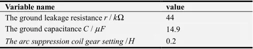
Table 1. Simulation parameter setting table.
Variable name value
The ground leakage resistance /r kΩ 44 The ground capacitanceC/µF 14.9
The arc suppression coil gear setting/H 0.2
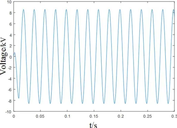
5.1. Normal Circumstances
current is Iɺi=12.36 65.99∠ A. When a current is injected into the system at 0.2 seconds, the voltage curve is as shown in Figure 4. It can be seen from the figure that after the current
injection, the C-phase voltage becomes 0, which verifies the feasibility of the zero-potential uninterrupted operation method of the proposed distribution network.
Figure 3. C-phase voltage change under normal conditions.
Figure 4. Phase C voltage change after taking measures under normal conditions.
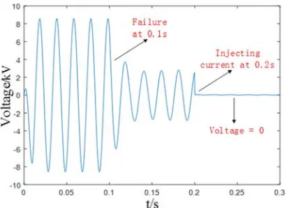
5.2. Small Resistance Ground Fault
When the system is 0.1s, a small resistance ground fault occurs in the C phase (the fault grounding resistance is 200Ω), and the voltage curve of the phase C of the working phase is shown in Figure 5. Substituting the parameters into equation (4), the neutral point injection current is
10.21 55.39 i
Iɺ = ∠ A. When a current is injected into the system at 0.2 seconds, the voltage curve is as shown in Figure 6. It can be seen from the figure that after the current injection, the C-phase voltage becomes 0, which verifies the feasibility of the zero-potential uninterrupted operation method of the proposed distribution network.
Figure 6. Phase C voltage change after taking measures with small resistance grounding.
5.3. Large Resistance Ground Fault
When the system is 0.1s, a large resistance ground fault occurs in the C phase (the fault grounding resistance is 1000Ω), and the voltage curve of the phase C of the working phase is shown in Figure 7. Substituting the parameters into equation (4), the neutral point injection current is Iɺi =11.66 22.34∠ A. When a current is injected into the system at 0.2 seconds, the voltage curve is as shown in Figure 8. It can be seen from the figure that after the current injection, the C-phase voltage becomes 0, which verifies the feasibility of the zero-potential uninterrupted operation method of the proposed distribution network.
Figure 7. Phase C voltage change with large resistance grounded.
Figure 8. Phase C voltage change after taking measures with large resistance
grounding.
6. Conclusion
In the distribution network, serious accidents will occur due to misuse and weak safety awareness during live working. In order to improve the reliability of power supply and personal safety, a new method based on injection current for zero-potential uninterrupted operation of distribution network is proposed. Here are some conclusions as follows:
By injecting current into the neutral point, the zero-sequence voltage is adjusted so that the neutral point voltage is equal to the value of the operating phase line voltage drop minus the operating phase power supply voltage, ensuring that the operating point voltage is zero;
Adopting the zero-potential uninterrupted operation method of the distribution network requires the shortest electrical distance from the live working point to the substation and the capacitance to ground. The Floyd algorithm can be used to calculate the shortest electrical distance, and the ground capacitance can be measured by the resonant grounding system;
The simulation is carried out by using PSCAD software, and the voltage curve comparison chart is taken when the working phase takes measures to provide support for the feasibility of the proposed method.
References
[1] LIU Jian, LIN Tao, ZHAO Jianghe, et al. Specific planning of distribution automation systems based on the requirement of service reliability [J], Power System Protection and Control, 2014 (11): 52-60.
[2] Nasibov F, Yorukoglu S, Gul O, et al. A feasibility study of live working in Turkish electricity distribution system [C]// International Conference on Live Maintenance. 2017. [3] ZHAO Hongshan, WANG Yingying, CHEN Song. Impact of
demand response on distribution system reliability [J], Automation of Electric Power Systems, 2015 (17): 49-55. [4] WU Simou, CAI Xiuwen, WANG Hailiang, et al. Planning
method and its application of distribution network based on power supply reliability [J], Proceeding of the CSU-EPSA, 2014, 26 (6): 70-75.
[5] Stepanov A M, Fakhrutdinova A N, Mamedov D V, et al. Phase goniometer calibration at observation of meteor tracks [J]. Kazan. Gos. Univ. Uchen. Zap. Ser. Fiz.-Mat. Nauki, 2009, 3 (3): 31–40.
[6] HU Yi, LIU Ka, PENG Yong, et al. Research status and development trend of live working key technology [J], High Voltage Engineering, 2014, 40 (7): 1921-1931.
[7] LI Tianyou. A review of the development of non-service interruption working technology in distribution network [J], DISTRIBUTION & UTILIZATION, 2015, 32 (05): 6-10+21. [8] Huang Z L, Zhang Q S, Liu C X, et al. The Application
[9] DENG Heming, CAI Wei, YU Xin, et al. Methods and safety protection of live working on 66kV transmission lines by aerial device with insulating boom [J], High Voltage Engineering, 2015, 41 (9): 3091-3096.
[10] WANG Jianming, SU Ziming, WANGJian-ming, et al. EMTP simulation calculation of bypass transformer operation in 10 kV distribution network [J], East China Electric Power, 2013, 41 (6): 1241-1245.
[11] YANG Xiaoxiang, MAO Yanping. Protective earthing of the bypass flexible cable for non-lackout working on 10kV distribution network [J], East China Electric Power, 2013 (08): 141-145.
[12] NI Zhijian, WANG Yang, LI Xiaolan, et al. Comparison on several finds of distribution network without power outage [J], NORTHEAST ELECTRIC POWER TECHNOLOGY, 2016 (9): 53-55.
[13] CHANG Zhongxue, SONG Guobing, HUANG Wei, et al. Phase voltage and current fault components based fault segment location method under single-phase earth fault in distribution network [J], Power System Technology, 2017 (7): 2363-2369.