http://www.sciencepublishinggroup.com/j/se doi: 10.11648/j.se.20190703.11
ISSN: 2376-8029 (Print); ISSN: 2376-8037 (Online)
Towards a Pattern-Based System Architecture for a Low
Power, Low Cost Ultra-Light Aircraft Flight Controller
Joseph R. Laracy
1, 2, 3, *, Thomas Marlowe
11Department of Mathematics and Computer Science, Seton Hall University, New Jersey, USA 2
Department of Systematic Theology, Seton Hall University, New Jersey, USA
3Department of Catholic Studies, Seton Hall University, New Jersey, USA
Email address:
*
Corresponding author
To cite this article:
Joseph R. Laracy, Thomas Marlowe. Towards a Pattern-Based System Architecture for a Low Power, Low Cost Ultra-Light Aircraft Flight Controller. Software Engineering. Vol. 7, No. 3, 2019, pp. 46-52. doi: 10.11648/j.se.20190703.11
Received: June 24, 2019; Accepted: July 23, 2019; Published: August 15, 2019
Abstract:
The definition and application of software and hardware patterns have been a major and very positive development in the field of computer engineering, in tandem with the deployment of agile and process architecture methodologies. In this article, we show how five time-triggered, real time system patterns developed by Michael J. Pont can be effectively employed to architect a low power, low cost flight controller. We adopt and apply Pont’s powerful pattern language for our research. The target platform is an ultra-light aircraft with tight constraints on mass and volume of any control hardware. Ultra-light in this context means that the aircraft has only one seat; weighs less than 254 pounds (115 kg) empty weight; has a maximum fuel capacity of 5 U.S. gallons (19 L); and has a top speed of 55 knots (102 km/h; 63 mph) calibrated airspeed at full power in level flight. We utilize the reliable Infineon C515C microcontroller, a member of the classic 8051 family of controllers for the hardware platform. This research makes a contribution to the engineering cybernetic issues of human-machine interface and control of an ultra-light aircraft.Keywords:
Architectural Patterns, Embedded Systems, Flight Controls, Real Time Systems, Cybernetics1. Introduction
Frank Buschmann et al. point out that “when experts work on a particular problem, it is unusual for them to tackle it by inventing a new solution that is completely distinct from existing ones. They often recall a similar problem they have already solved, and reuse the essence of the solution to solve the new problem [1].” The Austrian-American architect, Christopher Wolfgang Alexander, is widely regarded as the father of the patterns movement. His theories about the nature of design have impacted fields beyond architecture, including urban design and computer engineering [2]. In the area of computing, patterns “capture existing, well-proven experience in software [and hardware] development and help to promote good design practice [3].”
Design Patterns: Elements of Reusable Object-Oriented Software was and continues to be a major contribution to the field. The so-called “Gang of Four” authors captured a wealth
of software engineering experience about the design of object-oriented software. They elegantly describe twenty-three patterns that allow software engineers to create extensible, sophisticated, and reusable designs [4]. As Ayat Mesut points out, design patterns increase the maintainability, reusability, and understandability of a system. They may also promote the “Open-Closed Principle,” i.e., software should be open for extension and closed for inappropriate modification [5].
made a very substantial contribution with his highly regarded book, Patterns for Time-Triggered Embedded Systems [6]. In this paper, we utilize a number of Pont’s patterns.
A time-triggered computer system executes sets of tasks according to a pre-determined schedule. Such embedded systems typically involve the use of a single interrupt linked to the periodic overflow of a timer. The interrupt regulates a task scheduler—a simple real-time operating system. The scheduler initiates the tasks at predetermined time intervals. In contrast to event-triggered real-time systems, time-triggered systems offer a deterministic guarantee that all tasks will run and at their scheduled times. This level of reliability is, for example, often necessary in safety-critical systems such as biomedical devices and aerospace platforms.
We utilize the following Pont patterns in our research; chapter references are to [6].
a)Co-operative Scheduler (Chapters 13, 14). b)One-Shot ADC (Chapter 32).
c)Hardware PWM (Chapter 33). d)Naked LED (Chapter 7). e)MOSFET Driver (Chapter 7).
Below, we first provide a system overview, then, using the Pont patterns, describe each of the components. We then describe our simulation environment, consider future work and limitations, and provide conclusions.
2. System Overview
In the USA, the definition of ultralight vehicles specifies an aircraft much smaller and lighter than the definition in many other countries. According to the Federal Aviation
Administration (FAA), an ultralight: a)Has only one seat;
b)If powered, it weighs less than 254 pounds (115 kg) empty weight, excluding floats and safety devices; c)Has a maximum fuel capacity of 5 U.S. gallons (19 L);
and;
d)Has a top speed of 55 knots (102 km/h; 63 mph) calibrated airspeed at full power in level flight [7]. The lightweight, low-power, low-cost computer control system we propose is developed with the C programming language for the reliable Infineon C515C microcontroller. The C515C is a member of the classic 8051 family of controllers. While it is backward compatible with any 8051 compliant code, it has many special features that are exploited in this project. The most important hardware features include:
a)4 channel pulse width modulation unit; b)57 I/O lines;
c)3 timers/counters;
d)15 interrupts with 4 priority levels;
e)64 K ROM, 256 Bytes RAM, 2048 Bytes XRAM; and a f) CAN interface [8].
The MIT mathematician and engineer, Norbert Wiener, presciently identified a transdisciplinary approach in the mid-twentieth century for exploring regulatory systems—their structures, constraints, and possibilities. His cybernetic theory wisely emphasizes the importance of understanding and defining the functions and processes of systems involved in human-machine interactions where issues of communication, feedback, and control are non-trivial [9]. In this research, we strive to adhere to his principles and apply his insights.
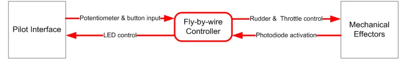
Figure 1. Level 0 Data Flow Diagram.
The entire flight control system is controlled by a cooperative scheduler, providing a solution that is both predictable and flexible. The scheduler is responsible for executing four main tasks: rudder control, throttle control, radiation detection, and attack. These tasks are explained in the following sections, together with the patterns that facilitate their implementation. The application domain is general enough to be useful for law enforcement, border security, and national defense applications. It might also, with changes to the non-navigational modules, have other applications in, for example, search-and-rescue, or monitoring of extreme weather events.
3. Scheduler Pattern
There are many advantages to a cooperative, time-triggered scheduler over an interrupt driven, preemptive one. One arises from its reliability and software safety. The cooperative
scheduler guarantees that all tasks will execute on time and for their complete duration. In the case of larger, more complex aerospace systems in which control surfaces may need to be updated many times per second to maintain stable flight, this predictability is necessary. The cooperative scheduler is also very efficient. Although it can be seen as another layer in the architecture, it is physically embedded within the rest of the code, and introduces very little overhead into the application—only seven bytes per task, or 28 bytes total.
Table 1. A sample set of task timings.
Task Frequency (ms) Duration (ms)
Rudder Control 25 10.0
Throttle Control 50 5.0
Radiation Detection 500 0.5
Attack 750 1.0
Every time that Throttle Control is scheduled to execute, so is Rudder Control. However, this problem is easily overcome by introducing staggered initial delays. For example, initializing Rudder Control with no delay and Throttle Control with a 1 ms delay solves that particular conflict. The delay process is continued for the other tasks. Therefore, the tick internal is now the GCF of the delays and frequencies, 1 ms.
The cooperative scheduler pattern utilizes function pointers. Like most technologies, when used properly, they simplify the design. However, when not implemented properly, they can make debugging impossible. The fundamental concept behind function pointers is that functions can be called by jumping to the memory address that begins their implementation, and that the implementing function can be changed without changing code in the callee, only in function pointer initialization.
The rest of the scheduler is a collection of functions supported by a common data structure. Below is the C framework for the Infineon class of controllers:
Sch51.h.
Figure 2. Representative Code for Sch51.C.
Sch51.C instantiates the task array: sTask SCH_tasks_G [SCH_MAX_TASKS]; using the sTask type, with the constant indicating the maximum number of tasks.
Pont’s design pattern calls for five functions to implement the required functionality in the scheduler. The first function called is the initialization routine, SCH_Init_T2(). The Infineon board provides 3 timers (0, 1, 2) but only timer 2 has auto-reload capability, so it will be used to drive the interrupt ticks. SCH_Init_T2() configures the data structures and initializes the system timer. The crystal oscillator is capable of
running at 12 Mhz, although the application tasks only require an interrupt every 1 ms. It is appropriate to mention an important system safety feature implicit in this architecture; namely, there is only one interrupt source, the tick. External ports are read through polling. Additional interrupts would only serve to complicate schedulability and break the deterministic timing scheme. (If, however, the final schedule includes unused time intervals, i.e., slack, a polling mechanism could be added to poll at those times to, for example, turn off radiation detection and attack in response to hardware malfunction.)
The timer overflow mentioned previously triggers the interrupt service routine, SCH_Update(). A conditional statement checks to see if a task is appointed to run and increments a RunMe flag if so. SCH_Update() does not actually run the task for reasons of reliability. In the scenario where a long task overruns the tick interval, ticks will be missed, and future tasks may not run at all. By creating a separating function to handle execution, no ticks will be missed, and the worst case scenario will only involve tasks run at the incorrect time, as opposed to not at all. The aforementioned execution function is referred to as the dispatcher, SCH_Dispatch_Tasks().
Another important function is the add task subroutine, SCH_Add_Task (Task_Name, Initial_Delay, Period). This function adds tasks to the array, specifying their initial delay and period. For example, SCH_Add_Task (Update_Throttle, 1, 5) adds the throttle control task to the scheduler. The time parameters are specified in tick units, not seconds. A zero in the second parameter indicates immediate execution such as for Update_Rudder and zero in the third parameter runs a task only once. SCH_Start (void) is a trivial function which sets a flag to begin the scheduling process [11].
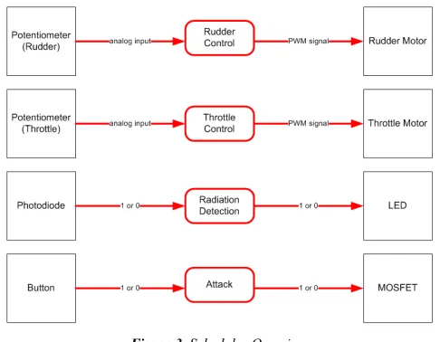
Figure 3. Scheduler Overview.
The scheduler controls the tasks shown above.
4. Rudder Control
pulse width modulation (Hardware PWM pattern) interfaced with a DC motor. Motor control is a discipline in itself, so only a simple control scheme is employed here to permit focus primarily on software architecture concerns. Fortunately, the C515C has a four channel PWM module included on the
board.
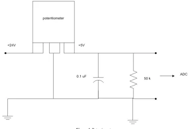
The pilot provides rudder input changes through a standard potentiometer. A potentiometer is a three terminal variable resistor with a knob controlling the middle pin. The knob on an old analog TV set is an example of such a device.
Figure 4. Potentiometer.
By arranging the potentiometer in the circuit specified above by the One-Shot ADC pattern, one can send the analog pilot input to the onboard ADC chip. The C515C uses a 10-bit, 8 channel ADC to pipe the information to port 6.
There are 9 possible rudder positions, so the digital value is converted to an integer ranging from 1 to 9. A value of 1 represents the leftmost position (hard left), 5 the center (straight ahead), and 9 the rightmost position (hard right). At this point, the Hardware PWM pattern provides the rest of the solution. The PWM scheme is implemented by setting pin 1.1 high for X time and low for Y time. The average voltage, Vavg, at the pin is what the motor detects as its input voltage. Vavg is defined by the duty cycle with period x+y as:
100 × y + x
x = cycle _
Duty (1)
Figure 5. Pulse Width for Rudder Control.
The rudder position which is now discretized as a value between 1 and 9 is translated into the appropriate x and y values. These values are determined experimentally by connecting a function generator to the motor and adjusting the period of the sinusoidal wave until the desired motor speed is achieved. Because the rudder position change is a small, quick movement, the PWM value should only be applied briefly, and then reset to 0. The PWM_Update (const tByte New_PWM_value) is called to set and reset the value [13].
5. Throttle Control
Throttle control uses the same two patterns discussed above, but applies them in a slightly different manner. While the aircraft is operating, the throttle will always have a positive value, unlike the rudder signal, which is usually set to zero. A similar potentiometer configuration is used for the throttle input, and the values are converted to an integer ranging from 0 to 25, with 0 being OFF and 25 being full throttle. In a model airplane implementation, a 20A DC motor is appropriate. Again, the duty cycle is determined empirically with a function generator.
incremented every 300ns to achieve the maximum frequency of 10Mhz. However, this application only requires frequencies in the mid-kilohertz range.
6. Radiation Detection
The goal of this task is to determine if the aircraft is being painted by electromagnetic radiation by an enemy radar, aircraft, or incoming missile. In this system, a photodiode is used to detect the radiation. Depending on the semiconductor materials used, photodiodes can detect radiation in the x-ray, ultra-violet (UV), visible, and infrared (IR) spectra [14].
The photodiode is connected to an input on the controller board. When it is exposed to radiation, a current is induced and a logical 1 is applied to the pin. The pin is checked whenever the radiation detection task is dispatched. A conditional statement will activate an onboard light emitting diode (LED) to advise the pilot that he has been painted by radiation if the photodiode is applying a voltage.
The Naked LED pattern is used to properly configure the hardware for the LED warning system. This pattern indicates that a resistor in series with the LED is necessary to dissipate the applied voltage. The diode can likely only accept 2 V but the board applies 5 V. The wire connecting the pin and the LED would need to drop the remaining 3 V, thereby frying the port and potentially the entire board! The required resistance is obtained through applying Ohm’s Law:
= ( − ) / (2)
A standard LED drops 2 V with 10 mA. Therefore R = 300 Ω [15].
Importantly, the use of patterns and the design of both software and electronic components with replaceable or configurable elements allows reuse not only of the software, but potentially of much of the hardware as configuration parameters change.
7. Attack
The attack task is the pilot response to his aircraft being painted by radiation such as enemy radar. This could be anything from firing countermeasures, to activating jamming hardware, to launching an offensive weapon at the source. (The use of function pointers allows a switch between modes simply by changing the system configuration. However, a change when all modules are deployed is not contemplated in this design.) No matter which action the pilot takes, the response will require a large current source with high switching frequencies to drive the appropriate electronic device. The MOSFET Driver pattern provides a straightforward solution to this problem.
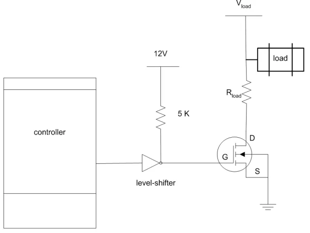
MOSFET stands for metal oxide semiconductor field effect transistor. A standard n-channel device can switch currents over 100A. However, these modules require a 12V power supply to function, and the microcontroller runs on a 5V power supply. Pont’s pattern suggests the following circuit to reconcile these differences:
Figure 6. MOSFET Driver Pattern Hardware Diagram.
A level-shifter integrated circuit is inserted between the board and the rest of the system as an additional level of protection. The shifter is simply a series network of six inverting buffers. In high current environments, such safety mechanisms are necessary [16].
The pilot initiates this task by depressing a “push button” on
accidental attack, this task will not execute unless the radiation detection task has already set a flag indicating a battle condition.
8. Simulation Environment
The Microvision 2 tool set provides a very good simulation environment for embedded microcontrollers. When a project is first instantiated in the tool, the engineer selects from a long list of possible controllers that the application has information about. This information is necessary to emulate all of the proprietary, board specific hardware such as memory interfaces, registers, port counts, and other specialized components.
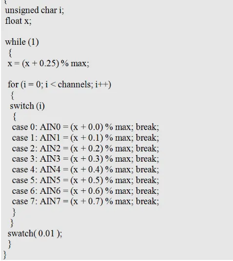
The debugger tool provides a very useful feature for interfacing the controller with the outside world. A C based macro language exists which permits the engineer to specify the behavior of a signal on an input port. This feature was used to simulate the analog inputs to the aircraft controller. A code example is provided below:
Figure 7. Representative example of simulator code.
Without a graphical user interface or command line to receive instant feedback, it is difficult to follow the execution of an embedded program. However, the memory view window, register view window, and break-point features greatly assist the engineering team in finding bugs and fixing them.
9. Future Work and Limitations
An interesting expansion of the system could involve two independent microcontrollers connected by the Control Area
Network (CAN) interface. The idea would be for one computer to accept pilot input and the other to directly control the mechanical effectors. CAN is a message-based communication system where each message can be up to eight bytes in length, achieving transmission rates up to 1 Mbit/s. A CAN configuration would designate one microcontroller as a master, and the other a worker. The scheduler running on the master would coordinate clock pulses and other low-level system activities for the network.
A second possibility would be to use a second microcontroller as a backup in case of damage or hardware failure. Inputs including acknowledgments would be echoed to the second controller, which would take over on receipt of a signal from the pilot (or the master controller) or after not receiving a signal over two or more ticks. We would also like to consider alternatives for the radiation detection and attack modules to allow this system to be used for other missions such as search-and-rescue or weather event monitoring, and to determine what changes or additional patterns would be needed for such applications.
An issue in the interceptor application lies in determining whether or not to attack. Clearly, sociopolitical concerns and context require human judgment. Communication access for the pilot may be terrain- or weather-dependent. Further, if threat identification is more complex than simple radiation detection and identification of friendly units, the application can be used only if the technical judgment can be made within a cycle. There are two reasons to think that the latter may not be a permanent, or practical restriction: first, processor speed and classification algorithms are both getting faster; second, the possibility exists for parallel processing of situation identification and classification over a small number of cycles. Also, the need to communicate resulting actions is not part of the application as described; rather, a separate system component will need to be added.
This second issue also applies to wider applications. For those that are non-critical, probabilistic solutions will be acceptable; it makes sense to respond to a search-and-rescue situation if there is a 90% chance that help is needed. But the main issue with extending the approach lies in specifying, designing, and implementing the equivalents to the radiation detection and attack phases with time-constrained hardware or firmware implementations—although occasional timeouts can be tolerated on such applications.
Finally, this technique has limited reach. First, it is applicable only to real-time/embedded systems applications with short cycles, preferably homogeneous or with minimal heterogeneity or conditional execution (except for go/no-go or execute/bypass decisions), and short, identifiable phases and deterministic components. Whether looping can be supported for incremental refinement of decisions needs to be investigated.
presented is localized, and it is unclear how it could be applied to either worker or master units in a distributed or coordinated system.
10. Conclusion
In this paper, we have shown how the use of real-time embedded system patterns can be combined with standard real-time and agile techniques to design a low-cost, low-power, reliable and configurable flight controller and much of its electronics, to support missions using ultra-light aircraft. While the application domain was aerospace, many of the architectural design principles can be extended into other domains, e.g., biomedical. It is our hope that this research further illustrates the importance of software and hardware patterns in computer engineering. There are nonetheless several limitations to this work: to the application as described, to its extension to other applications, and to its utility for software development.
References
[1] F. Buschmann et al., Pattern-Oriented Software Architecture: A System of Patterns, vol. 1 (New York: Wiley, 1996), 2.
[2] See C. Alexander, Notes on the Synthesis of Form (Cambridge, MA: Harvard University Press, 1964); C. Alexander et al., A Pattern Language: Towns, Buildings, Construction (New York: Oxford University Press, 1977).
[3] Buschmann et al., Pattern-Oriented Software Architecture Volume 1, 1:1.
[4] E. Gamma et al., Design Patterns: Elements of Reusable Object-Oriented Software (Reading, MA: Addison-Wesley Professional, 1994).
[5] Ayat Mesut, “Effect of Some Software Design Patterns on Real Time Software Performance” (Master of Science, Middle East Technical University, 2010), 1.
[6] M. Pont, Patterns for Time-Triggered Embedded Systems: Building Reliable Applications with the 8051 Family of Microcontrollers (New York: Addison-Wesley, 2001).
[7] E-CFR: TITLE 14—Aeronautics and Space, Electronic Code of Federal Regulations, vol. TITLE 14—Aeronautics and Space,
accessed May 2, 2019,
https://www.ecfr.gov/cgi-bin/text-idx?tpl=/ecfrbrowse/Title14/ 14cfr103_main_02.tpl.
[8] Pont, Patterns for Time-Triggered Embedded Systems, 30.
[9] Norbert Wiener, Cybernetics, or Control and Communication in the Animal and the Machine, 2nd ed. (Cambridge: The MIT Press, 1965).
[10] Pont, Patterns for Time-Triggered Embedded Systems, 255– 296.
[11] Pont, Patterns for Time-Triggered Embedded Systems, 254– 296.
[12] Pont, Patterns for Time-Triggered Embedded Systems, 757– 756.
[13] Pont, Patterns for Time-Triggered Embedded Systems, 807– 839.
[14] According to the IEEE specifications, “photodiodes are a two-electrode, radiation-sensitive junction formed in a semiconductor material in which the reverse current varies with illumination. Photodiodes are used for the detection of optical power and for the conversion of optical power to electrical power. Photodiodes can be PN, PIN, or avalanche. PN photodiodes feature a two-electrode, radiation-sensitive PN junction formed in a semiconductor material in which the reverse current varies with illumination. PIN photodiodes are diodes with a large intrinsic region sandwiched between P-doped and N-doped semiconducting regions. Photons absorbed in this region create electron-hole pairs that are then separated by an electric field, thus generating an electric current in a load circuit. Avalanche photodiodes are devices that utilize avalanche multiplication of photocurrent by means of hole-electrons created by absorbed photons. When the device's reverse-bias voltage nears breakdown level, the hole-electron pairs collide with ions to create additional hole-electron pairs, thus achieving a signal gain.” “Photodiodes Information,” IEEE GlobalSpec Engineering 360, accessed
April 29, 2019,
https://www.globalspec.com/learnmore/optics_optical_compo nents/optoelectronics/photodiodes.
[15] Pont, Patterns for Time-Triggered Embedded Systems, 110– 114.