Article
Passivity-Based
L
2
-Gain Adaptive Control for
Battery/Supercapacitor Hybrid Energy Storage
System in Electric Vehicles
Xizheng Zhang 1,2*, Zhangyu Lu 1
1 School of Electrical and Information Engineering, Hunan Institute of Engineering, Xiangtan 411104, China; zxz@ieee.org
2 The Key Laboratory of Automotive Power and Transmission system of Hunan Province, Hunan Institute of Engineering, Xiangtan 411104, China; zxz@ieee.org
* Correspondence: zxz@ieee.org; Tel.: +86-732-58680339
Abstract: Battery/Supercapacitor(SC) current tracking control is a key issue for hybrid energy storage system (HESS) in electric vehicles. An innovative passivity-based L2-gain adaptive control
(PBL2AC) based on port-controlled Hamiltonian model with dissipativity (PCHD) for reference
current tracking and bus voltage stability in HESS is presented. The developed PCHD model has considered both parameter variations and external disturbances. By using L2-gain disturbance
attenuation, the PBL2AC ensures robust reference current tracking and stable bus voltage.
Moreover, adaptive mechanism is adopted to estimate the electrical parameters. To validate the proposed control scheme for HESS, simulations and experiments were done and compared with traditional PID and sliding mode control under several typical driving cycles, and results show that the effectiveness of the proposed controller can be confirmed.
Keywords: hybrid energy storage system; L2-gain disturbance attenuation; passivity-based control;
port-controlled Hamiltonian model
1. Introduction
Hybrid energy storage system (HESS) have played a significant role in the energy provision and economic benefit of hybrid electric vehicles (HEVs), plug-in hybrid electric vehicles (PHEVs), and pure electric vehicles (pEVs) due to its strong adaptability to the pulsating change in the required power of the vehicle [1-3]. Among different energy storage devices, the battery and the supercapacitor (SC) are most suitable for EVs. Generally, batteries have high energy density to provide enough energy needed by long driving distance; while their power density is insufficient to supply high pulse power. Compared to batteries, SC has a much higher power density and its life is much longer (>1 million cycles). What’s more, SC can provide fast and pulsating energy output [4,5]. Therefore, by combination of the battery and the SC to form the HESS for EVs, high energy density and power density can be obtained simultaneously as well as the life span of the battery is prolonged [6,7].
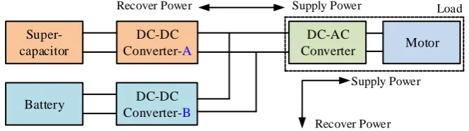
Many topologies have been developed to combine the battery and the SC to form certain kind of HESS [8-10]. Generally, these topologies can be concluded into three major types: passive, semi-active, and fully-active. In the passive structure of HESS, the battery and the SC are directly connected in parallel as in Fig.1, where neither the DC-DC converter A or the B are valid. Although this structure is simplest, the battery and the SC are not controlled due to the lack of the converter, and the voltages of the battery and the SC must be equal. The power distribution between battery and SC is entirely dependent on their internal resistances. The SC can only output or receive power when the load power is abrupt, and its power compensation capability is limited. In the semi-active structure of HESS, the battery (or SC) is connected in series with the DC-DC converter and then
connected in parallel with the SC (or battery), where either the DC-DC converter A or the B is valid. Since this structure utilizes only one DC-DC converter, whose voltage is determined by the SC (or battery) voltage, it is a good compromise between performance and cost, and has been employed in many applications. In the fully-active structure of HESS, the battery and the SC are each connected in series with a DC-DC converter and then connected in parallel, where both the DC-DC converter A
and the B are valid. This structure covers all the advantages of two semi-active structural HESS, with greater flexibility and regulation. Although the dual DC-DC converter makes the control difficult, it is the only option for some applications [11,12], where the DC-link voltage is required to keep stable. For this purpose, the fully-active topology is considered in this work.
Super-capacitor
DC-DC Converter-A
DC-AC
Converter Motor
Recover Power Supply Power
Supply Power Load
Recover Power
Battery DC-DC
Converter-B
Figure. 1. Three kinds of structure of HESS. Passive: converters A and B are invalid; Semi-active: either
converter A or B is valid; Fully-active: both converter A and B are valid.
The focus research in HESS is how to split the required power into the power supplies (batteries, SCs and others) in a cheap and efficient way. Consequently, most of the developed schemes devoted to design various energy management strategies (EMSs) [13-18], which act as upper control to output reference current/power, only few of designs consider the interactions among different components in HESS to implement the lower tracking control [19,20]. However, the HESS won’t perform as well as the EMS desires once the interactions are not taken into consideration, and the current/power output from the battery/SC may not precisely equal that of the designed tracking control loop. Thus, the developed EMSs scheme won’t operate as expected if the underlying control design is lack or unwell-behaved.
Mebarki et al. studied the passive HESS with proton exchange membrane fuel cell (PEMFC) and a battery bank for electric vehicle [21]. Tang et al. established the mathematical model of parallel connection of the battery and the supercapacitors, and quantitatively analyzed the improvements of HESS performance and its influencing factors [8]. Camara et al. designed a new control for a semi-active HESS with battery and SC used in Hybrid vehicles [22]. Wang et al. proposed a new multimode HESS (semi-active) which can choose proper operating modes according to the driving modes of the EV and the status of the power sources [23]. Fadil et al. dealt with the problem of controlling a HESS for electric vehicles with fuel cell and SC [24]. After considering converters' large-signal dynamics and FC’s nonlinear characteristics, a nonlinear model and a nonlinear controller is developed based on Lyapunov stability design techniques. In the micro-combined heat and power generation system, Wang et al. proposed a novel control scheme for domestic HESS with battery and SC [25]. The reference current and low frequency power of the battery are determined according to the the low frequency component of the SC voltage. Song et al. proposed a Lyapunov-function based control scheme with two classical sliding mode controllers (SMC) for a fully-active HESS based on a 5th-order averaged model [20]. However, all the above works neglected the parameter variations or disturbances either lied in the system or generated from the outside. Since the driving conditions of HEV are various and time-varying, thus, the underlying control performance (current or voltage) may not be satisfied or optimal in real application.
estimated dynamically by the proposed projection operators and no specific parameter is involved. To obtain the optimal power distribution in different temperatures, SoC and driving cycles, a reinforcement learning (RL)-based EMS is developed with satisfied adaptability and robustness [27]. In [28-30], disturbance rejection and disturbance observer based controls are proposed for PEMFC and battery/SC system in HEVs, respectively. In [31,32], the advanced predictive control is also applied into EMS.
The port controlled hamiltonian (PCH) model, initially proposed by van der Schaft [33], has been widely researched in numerous works [34]. PCH systems provide a design framework for many mechanical-electrical systems such as fuel cell [35], wind turbine [36], power system [37], PMSM motor [38] and mechanical systems [39]. Ortega introduced a new energy-shaping and damping injection scheme to PCH systems based on the passivity-based control (PBC) [40]. In [41], the original system is converted into a PCH model, and the disturbance-rejection controller is designed through interconnection and damping assignment (IDA) method. Wu et al. presented a PCH based strong tracking control of HESS system for power coordinated allocation in spit of the load change of the HEV [42]. Benmouna et al. developed the mathematical modeling using PCH approach and designed a smart EMS in HEV in presence of EC faults with the stability guarantee [43]. However, to our best knowledge, for HEV there are few works in the literature on application of PCH theory into the HESS systems with SC and battery.
Motivated by above discussion, in this paper, the L2-gain adaptive robust control (PBL2AC)
based on port-controlled Hamiltonian model with dissipativity (PCHD) is developed for the HESS. It has the following characteristics: (i) According to the dissipative structural characteristics and energy balance of HESS, state space average model (SSAM) and the error dynamic system of the PCHD model of HESS with the battery and the supercapacitor considering the influence of external disturbance and parameter perturbation are established; (ii) The energy storage function of the error dynamics is obtained according to the requirements of parameter perturbation compensation. Base on this, a new adaptive L2 gain control method is designed, where the adaptive parameter control is
used to compensate the component parameter perturbation and the L2 gain control is used to
suppress the external interference. The developed HESS control can track the reference battery/SC current and keep the bus voltage constant as well as ensure the asymptotic convergence and the robust tracking of HESS. To the best of our knowledgy, the idea is novel and first contributed to the underlying control of HESS for HEV.
The rest of the paper is organized as follows: In Section 2, the SSAM model and the PCHD of HESS are formulated. Section 3 develops the detailed design of the proposed PBL2AC control scheme. In Section 4, the proposed PBL2AC controller is tested and compared with the PID and the SMC controllers under several typical driving cycles. The effectiveness and robustness of PBL2AC are validated and analyzed. Conclusions are made in Section 5.
2.PCHD model of the HESS system for HEV
Considering cost and efficiency, the fully-active HESS is selected in this work for HEV, and its circuit diagram is shown in Fig 2, which consists of a battery pack, a supercapacitor pack, two sets of bi-directional DC/DC converter, a DC/AC inverter and an electrical motor. The SC is connected in series with the DC/DC converter and then connected to the load in parallel with the battery. The battery is used as the main energy source, and the output power is directly applied to the load to maintain the load side voltage stability. The supercapacitor is used as an auxiliary energy source and is connected to the vehicle load through a DC/DC converter to provide peak power to the load and recover braking energy [44]. This structure can enable supercapacitor work in wider voltage range and restrain in the damage of voltage fluctuation and peak current to the battery.
The required power of the vehicle load is Pdem, and is assumed to be predicted. Thus, the load
can be modeled as a current source with varying current im. The DC-DC converters consist of two
VE
S1
L1 L2
S2 S3 S4 D1 D2 D3 D4 C R Csc Rsc Vdc Vsc im u1
1–u1 1–u2
u2
Load
i1 i2
Figure 2. The circuit of the fully-active HESS in this work.
2.1. The state space average model of HESS
Based on Kirchhoff's circuit theory, the circuit model of the hybrid energy storage system in EV in Fig.2 is given by the following equation
E
1 1 1 dc
2 2 2 dc sc
dc
dc 1 1 2 2
sc
sc 2
m
sc
sc
L i
V
u V
L i
u V
V
V
CV
i
u i
u i
R
V
C V
i
R
=
−
= −
+
= −
+
+
= − −
&
&
&
&
, (1)
where the symbol "
x
" represents the first derivative of the variable x with respect to time; the control signals of the switches S1 and S2, S3 and S4 are u1, u2 = [0, 1], where ui= 1 indicates that theswitch is on, and ui = 0 indicates that the switch is off, i=1, 2; it should be noted that the control
signals of the switch S1 and S2, S3 and S4 are complementary; VE, Vdc, Vsc are the nominal
electromotive force of the battery, the capacitor output voltage of the bus, and the supercapacitor voltage; L1, L2 is the inductance of the inductors; C and Csc are the capacitance values of the bus
capacitor and the supercapacitor, respectively; i1, i2, and im are the first inductor, the second inductor,
and the vehicle load current respectively; R, Rsc are the internal resistance values of the bus capacitor
and the supercapacitor, respectively.
During the actual driving of the vehicle, the parameter values of the circuit components are prone to perturbation with the influence of temperature rise, noise, working frequency and other conditions; and the aging of the equipment itself is also attenuated, so that the inductance and capacitance value L1, L2, C and Csc are difficult to accurately pre-acquire or determine. To describe
this time-varying characteristic, the inductance and capacitance values are expressed as follows:
1,n 1 2, 2 n sc,n sc
0
0
0
0
0
0
0
0
0
0
0
0
n
L
L
L
L
C
C
C
C
=
θ
, (2)where L1,n, L2,n, Cn and Csc,n are the known nominal values of the electrical parameters; θ=[θ1, θ2, θ3, θ4]T is the unknown parameter vector, θi is the element of θ, i=1,2,3,4.
In addition, due to changes in road conditions and electrical interference in vehicle drivin g, the HESS should also consider various external interference. Assuming that the external int erference vector is d(t)=[d1,d2,d3,d4]T, di is the element component of the interference vector, i=1,
E
1,n 1 1 1 dc 1
2,n 2 2 2 dc sc 2
dc
n 3 dc m 1 1 2 2 3
sc
sc,n 4 sc 2 4
sc
L
i
V
u V
d
L
i
u V
V
d
V
C
V
i
u i
u i
d
R
V
C
V
i
d
R
=
−
+
= −
+
+
= −
+
+
+
= − −
+
&
&
&
&
, (3)
2.2. The port-controlled Hamiltonian model of HESS
The energy storage function H and the energy dissipative function Hr of HESS are defined as T
1
( )
2
H
x
=
x Qx
, (4)T r
1
( )
2
H
x
=
x Dx
(5)Where the diagonal matrix
Q
=
d
iag L L C C
{ ,
1 2, ,
sc}
0
, the adjustment matrix for the damping parameterD
=
d
iag
{0, 0,
R
−1,R
sc−1}
0
, x is the state vector.It can be found from Eq. (4) that the energy storage function of the on-board hybrid energy storage system is the sum of the inductor energy storage and the capacitor energy storage of the system, and the dissipated energy is the sum of the electric energy consumed by the bus capacitance resistance and the super capacitor resistance.
By calculating the partial differential for Eq.(4), we have 1 T 1 2 dc sc
( ) [ ]
H
Q− i i V V
= =
x x x ;
therefore, it is derived that the port-controlled Hamiltonian model with dissipativity (PHCD) of the hybrid energy storage system is:
( )
( )
H
g
(
)
( )
t
=
−
+
+
x
x
J u
D
x,u
Kd
x
&
, (6)where the state vector x, the input function
g x,u
(
)
and the coefficient matrixJ u
( )
,D
,K
are asfollowing:
x=[L1i1 L2i2 CVdc CscVsc]T
T
1 2 3 4
(
) (
)
g
x,u
=
g
g
g
g
, with
g
1=
V
E,
g
2=
0
,
1
3 m dc
g
= −
i
R V
−,
g
4=
0
1
2
1 2
0 0 0
0 0 1
( )
0 0
0 1 0 0
u u u u − − = −
J u
,
11
0 0 0 0 0 0 0 0
0 0 0
0 0 0 sc
R R − − =
D
,
K
=
diag
{1,1,1,1}
;
It can be seen that the interconnect coefficient matrix T
( )= − ( )
J u J u is an anti-symmetric matrix and thus satisfies
x J u x
T( )
=
0
. The damping parameter0
D
is a positive definite diagonal matrix.3.1. The desired equilibrium of the system states
In order to ensure stable operation of the hybrid energy storage system, the bus voltage should be kept constant. This work investigates the robust tracking of the battery/SC currents to the vehicle's required current while the bus voltage is stable, thus the control objectives are the following:
(i)stabilization of the bus voltage;
(ii)robust tracking of the battery/SC current.
When the energy storage system is in steady state operation, the desired value of the system state is:
*
=
[
1,
2,
dc,
sc]
T
V
V
i
i
v
; the state equilibrium isx
=
[
x
1x
2x
3x
4]
T; in steady state, after obtaining the vehicle states and the sensed signals, the desired battery currenti
1
is calculated, and the bus capacitor voltage is stabilized at desired value simultaneously, that is
V
dcV
dc
=
,i
1i
1
=
. at this time, the derivative of the state variable is equal to zero, that is d 0dt x x
= =
x
. Then, from Eq. (1), the desired steady-state values of the output voltage/current of the supercapacitor are calculated as following
E dc
sc sc dc 1
dc sc 2 sc m V V
V R V i i
R V V i R = − + = −
, (7)
The state equilibrium of the system can be obtained as following:
T 1/2 E dc 2
1 1 sc dc sc sc dc 1
sc dc
(m V )
L V
L i V CV C R V i i
R R V
= − − +
x , (8)
Accordingly, the control input of the switches in steady state is E sc 1 2
dc dc
[u u, ] V V
V V = .
3.2. L2-gain adaptive control (PBL2AC)
Define the tracking error of the system states as following:
e
= −
x
x x
, (9)If there is external interference and parameter uncertainty, the tracking error is gradually approached to zero, that is
x
e→
0
, the robust control target is achieved asx
=
[ , , , ]
x x x x
1 2 3 4 T→
x
. This work proposes the design of the nonlinear H∞ robust adaptive control, where the adaptive technique is adopted to identify the system parameters online, and the nonlinear H∞ technique isutilized to suppress the influence of external interference on the control performance at a satisfactory level γ. To achieve asymptotically tracking of desired state
x
, the desired energy function of the closed-loop system based on the tracking error is defined as:2 2 2 2
1 1 2 2 3 3 4 4
1 2
1
1
1
1
( )
(
)
(
)
(
)
(
)
2
2
2
2
d
sc
H
x
x
x
x
x
x
x
x
L
L
C
C
=
−
+
−
+
−
+
−
x
, (10)state, the state equation (6) is transformed into a new dynamical system with considering external disturbance and parameter perturbation as following:
( )
(
)
1( )
e
=
−
H
d e+
+
t
x
&
J u
D
x
Ξ
Kd
, (11)where the state partial derivative
H
d( )
x
e=
H
d( ) /
x
e
x
e , and the matrix1
( ( )
)
( )
g
(
)
=
−
−
+
Ξ
J u
D v
F θ v
&
x,u
,F θ
( )
=
diag L
{
1,n 1
L
2,n 2
C
n 3
C
sc,n 4
}
.Due to the time-varying perturbation of the system parameters, an online estimation of the parameters is required. Let T
1 2 3 4
ˆ
=
(
ˆ
ˆ
ˆ
ˆ
)
θ
denote the estimated vector of parametersθ
, and the corresponding time-varying parameter matrix is F θ( )ˆ =diag L{ 1,n 1
ˆ L2,n
ˆ2 Cn
ˆ3 Csc,n
ˆ4}.Rewrite Eq. (11) as the following :
( )
(
)
2( ) [ ( )
( )]
ˆ
e
H
d et
=
−
+
+
−
−
x
&
J u
D
x
Ξ
Kd
F θ
F θ v
&
, (12) whereΞ
2=
J u
( )
−
D v
−
F θ v
( )
ˆ
&
+
g
(
x,u
)
;Given the penalty signal z and a disturbance attenuation level γ>0, after obtaining the damping adjustment parameter, the tracking error and the parameter estimation, the duty cycle of the DC-DC converter can be derived, and the PWM modulation waveform to control the switching action of the switching transistor is generated to perform the underlying voltage and current control.
Let the penalty signal z be defined as follow:
T
(
e)
d(
e)
z
= −
h
x
G
H
x
, (13)where
G
H
d(
x
e)
is the standard output of the Hamilton system,G
=
diag
{1,1,1,1}
; is a matrixof weighting coefficients and
h
(0)
=
0
is satisfied.Before the controller design, the matrix is defined as
T 2
1
1
||
(
)
||
2
2
h
e=
+
Μ
I
x G I
, (14)Theorem 1 gives the stability analysis and proof of the proposed PBL2AC control.
Theorem 1.Consider the system (6) with the desired equilibrium x* and the penalty signal z in (13). For any given γ>0, the L2 disturbance attenuation objective is achieved by the following feedback control law
E
1 1 1 1 1 d 1 1
dc
1
ˆ
(
)(
)
u
V
L
i
m
r
i
i
V
= −
−
+
+
−
, (15)E
dc dc 1 1 1 1 d 3 d
2 3 dc m 1 1 1 dc dc
2 2 dc dc dc 2
ˆ
1
ˆ
(
)
(
)
V
V
i
V
L
m
r
m
r
u
C V
i
i
i
i
V
V
i
R
i
V
V
V
i
+
+
+
=
+
−
−
−
+
−
−
−
&
&
, (16)
1,n
1 1 1 1
1
2,n
2 2 2 2
2
n
3 dc dc dc
3
sc,n
4 sc sc sc
4
ˆ
(
)
ˆ
)
ˆ
(
)
ˆ
(
)
L
i
i
i
p
L
i
i
i
p
C
V
V
V
p
C
V
V
V
p
= −
−
= −
−
= −
−
= −
−
&
&
&
&
&
&
&
&
, (17)
(
)
d 1 sc sc sc 4 sc 4
sc sc
1
ˆ
C
r
i
R V
V
m
V
V
=
+
+
−
−
&
, (18)where Xe=diag{xe(1),xe(2), xe(3), xe(4)}, P=diag{p1, p2, p3, p4}>0, and mj is the j-th element in the
diagonals of M, j=1,2,3,4.
Proof. Consider the following Lyapunov function
1
ˆ
ˆ
( )
(
)
(
)
2
T d
V
=
H
x
+
θ θ
−
Ρ θ θ
−
, (19)It can be found in Eq. (13) that a energy term is introduced to depict the parameter estimation error
θ
−
θ
ˆ
, and this new energy function is defined as the Lyapunov function of the the state error system in Eq. (6). If the tracking error gradually approaches zero with external disturbance and parameter uncertainty, the robust control is achieved.By calculating the derivative on both sides of the Eq. (19), one can obtain the following:
(
)
Tˆ
Tˆ
(
)
( (
))
d e e
V
&
=
H
x
x
&
−
Ρ θ θ
−
θ
&
, (20) To estimate the time-varying parameter online, the adaptive law is designed as Eq. (17) and substitute Eq. (15) , (16) into Eq. (20) and after some simplification,one can obtain:(
)
T(
)
T2
(
)
(
)
(
)
(
( ))
d e d e d e
V
&
= −
H
x
D
H
x
+
H
x
Ξ
+
Kd
t
, (21)Based on the vector inner product inequality
T T
T
2
+
a a
b b
a b
, combining Eq. (21) and Eq. (18) yields:(
)
(
)
(
)
(
)
(
) (
)
(
)
(
)
T T 2T T T 2
2
T T 2 2 2
2
(
)
(
)
(
)
(
( ))
1
1
(
)
||
(
) ||
(
)
(
)
(
( ))
|| ||
2
2
1
(
)
(
)
(
)
|| ( ) ||
|| ||
2
d e d e d e
d e e d e d e
d e d e d e
V
H
H
H
t
H
h
H
H
t
z
H
H
H
t
z
= −
+
+
= −
−
+
+
−
−
−
+
+
−
&
x
D
x
x
Ξ
Kd
x
D
x G
x
x
Ξ
Kd
x
D
M
x
x
Ξ
d
,
(22)
where the notation ||.|| represents the Euclidean norm,
is the design parameter, and I is the unit matrix.Through state feedback, the additional damping is injected into the PCHD as following
2
= −
(
+
R
d)
H
d(
e)
Ξ
Μ
x
, (23)Hence, by substituting Eq. (23) into the right side of Eq. (22) and setting the non-negative definite function
(
) (
T)
(
e)
d(
e)
d d(
e)
W
x
=
H
x
D
+
R
H
x
,W
(0)
=
0
(24)Based on Lyapunov stability theory and , Eq. (24) means that the following γ-dissipation inequality holds:
(
2 2 2)
1
(
)
|| ( ) ||
|| ||
2
e
V
&
+
W
x
−
d
t
−
z
d
, (25)This means the γ dissipation inequality holds and the Hamiltonian function Hd serves as the
storage function for the closed loop system. As the La Salle-Yoshizawa Theorem pointed out in [45], the inequality (24) ensures the following performance: 1) the estimation error of the parameters will asymptotically converge to zero; 2) L2-gain from the disturbance d to the penalty signal z is less than
the given level γ; 3) if d is square integrable, then xe is uniformly bounded.
From Eq. (15) and (16), the control inputs for the calculation of the switching signals are and the damping adjustment parameters rd can be calculated as Eq. (18) and Eq. (14), respectively.
Fig. 3 presents the schematic diagram of the proposed PBL2AC control for hybrid energy storage system in electric vehicles. The global flow chart of the proposed PBL2AC control algorithm composed of twelve steps is presented in Fig. 4.
+ −
PBL2AC controller
Driving signals
Calculate PWM duty ratio Eq. (15), (16)
DC-DC Converter Calculate the
equilibrium, Eq. (7), (8) Energy
managements trategy(EMS) dc
V
1
i
m
i
x
x
e
x T
1 2 3 4
ˆ=( ˆ ˆ ˆ ˆ)
θ Rd=diag{r , r , r , r }dddd 2
u
1
u
Damping inject Eq. (14), (17) Adaptive
laws Eq.(17)
Figure 3. The diagram of the proposed PBL2AC controller.
Initialization, input the desired voltage V* dc
Start
Upate the parameter estimation θˆ
Control calculation u1, u2
Output the desired PWM signals
Yes No
End Read vehicle states and the
samples Vdc, Vsc, i1,i2
Execute EMS scheme, calculate currents
im, i *
dc and the system equilibrium x *
Input parameters P,γ
Calculate the damping parameter rd
The trip of this round end ? Define the penalty signal z
4. Results and analysis
To evaluate the estimation accuracy and the robust control performance, the proposed PBL2AC control was tested and compared with the traditional PID control and the sliding mode control (SMC) under several typical driving cycles. The system parameters of HESS were chosen as in Table 1. The controller parameters were set as: pi=2.5, h(xe)=diag{0.05, 0.05,0.01,0.01}, K=diag{1, 1, 1, 1}, γ=0.1, x* and rd were solved by (8) and (18), respectively. The sinusoidal disturbances d were
emulated by the single-phase output of the AC source.
In the following, several different performance aspects of the proposed PBL2AC control are tested on the ADVISOR/SIMULINK platform and experimental control prototype, including the parameter estimation, the comparisons of the PBL2AC to the PID and the SMC controllers, the robust tracking under different driving cycles and the energy efficiency analysis.
Table 1. The system parameters of HESS.
Component Parameters Value
Battery Nominal voltage 120 V
SC
Capacitance 3.0 F
Nominal voltage 140 V
Nominal current 20 A Resistive loss 8.7 kΩ
DC–DC converter
Battery side inductance L1 = 10 mH SC side inductance L2 = 10 mH Capacitance on the DC bus 3850 μF
Nominal voltage on the DC bus 200 V Total resistive loss in the circuit 900 Ω 4.1. Parameter Estimation of the propose scheme
0
0.2
0.4
0.6
0.8
1
5
10
15
20
L
1(
mH
)
Actual L
1Estimation of L
1
0
0.2
0.4
0.6
0.8
1
5
10
15
20
25
Time (s)
L
2(
mH
)
Actual L
2Estimation of L
2
Figure 5. Inductor estimation of the proposed control. (a) Estimation and real value curves of the inductor L1;(b) Estimation and real value curves of the inductor L2.
0
0.2
0.4
0.6
0.8
1
3800
3850
3900
3950
C
(
uF
)
Estimation of C
Actual value of C
0
0.2
0.4
0.6
0.8
1
300
350
Time (s)
C
sc(
F
)
Actual value of C
sc
Estimation of C
sc
Figure 6. Capacitor estimation of the proposed control. (a) Estimation and real value curves of the capacitor C;(b) Estimation and real value curves of the capacitor CSC.
4.2. Comparisons of the proposed controller to the PID and the SMC controllers
(b) (a)
To investigate the performance and the robustness of the PBL2AC control, comparisons are done with the PID control and the SMC control methods. Under the New European Driving Cycle (NEDC) driving cycle, the voltage regulation curves with three control methods are shown in Fig. 7~Fig. 9. They show that PBL2AC possesses least regulation error, SMC possesses the second, for PID the worst, and the maximal ripple ratio decreases from 23.5% (47 V) of PID to 1.3% (2.6 V) of PBL2AC. The SC voltages fluctuate due to the charging/discharging operation, and the battery voltages experience a little slow decrease due to the energy output. Fig. 10 and Fig. 11 give the power demand of NEDC, reference currents and controlled duty ratio of PBL2AC.
From these, we can conclude that the voltages of SC and battery under three controllers keep stable. However, as concluded in Table 2, the bus voltage has least regulation error with PBL2AC than others.
0
200
400
600
800
1000
170
180
190
200
210
220
B
u
s
v
o
lt
a
g
e
(
V
)
V
dc *
V
dc
0
200
400
600
800
1000
110
120
130
140
150
Time (s)
B
a
t/
S
C
v
o
lt
a
g
e
(
V
)
V
E
V
SC
Figure 7. Voltage regulation of the PI control under the NEDC driving cycle. (a) DC bus voltage;(b) Battery and SC voltages.
0 200 400 600 800 1000 194 196 198 200 202 204 B u s v o lt a g e ( V ) V dc * V dc
0 200 400 600 800 1000
110 120 130 140 150 Time (s) B a t/ S C v o lt a g e ( V ) V E V SC
Figure 8. Voltage regulation of the SMC control under the NEDC driving cycle. (a) DC bus voltage; (b) Battery and SC voltages.
0
200
400
600
800
1000
198.5
199
199.5
200
200.5
201
B
u
s
v
o
lt
a
g
e
(
V
)
V
dc *V
dc0
200
400
600
800
1000
115
120
125
130
135
140
145
Time (s)
B
a
t/
S
C
v
o
lt
a
g
e
(
V
)
V
EV
SCFigure 9. Voltage regulation of the proposed PBL2AC control under the NEDC driving cycle. (a) DC bus voltage;(b) Battery and SC voltages.
(b) (a) (b)
0
200
400
600
800
1000
-2000
0
2000
4000
P
o
w
e
r
d
e
m
a
n
d
(
W
)
P
dem
0
200
400
600
800
1000
-20
0
20
40
Time (s)
C
u
rr
e
n
t
(A
)
i
mi
1 *
i
2 *
Figure 10. Power demand and reference currents of the proposed PBL2AC control under the NEDC driving cycle. (a) Power demand;(b) Reference currents of load, battery, SC voltages.
0 200 400 600 800 1000
0 0.2 0.4 0.6 0.8 1
Time (s)
D
u
ty
r
a
ti
o
d1
Figure 11. Duty ratio d1 of the proposed PBL2AC control under the NEDC driving cycle.
Table 2. Bus voltage regulation errors of PID, SMC and PBL2AC.
Control SC voltage (V) Battery
voltage(V)
Bus voltage
(percentage)
PID 3.2 2.4 13%
SMC 2.7 1.9 4.1%
PBL2AC 4.4 2.5 1.3%
4.3. Robust tracking under different driving cycles
To investigate the tracking ability under different driving cycles, the tracking responses are tested and obtained under three driving cycles: the China's Urban Driving Cycle (CUDC), the long Arterial driving cycle and the hybrid driving cycle as shown in Fig. 12~Fig. 17.
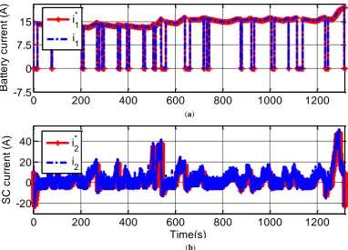
First, under the CUDC driving cycle, Fig. 12 gives the voltage regulation curves and results show that the maximal ripple ratio of bus voltage is less than 2.5%. Fig. 13 presents the power demand of CUDC and reference currents of PBL2AC. Fig. 14 shows the current tracking results, and it can be seen that despite of parameter variation and driving condition changes, the currents of SC and battery accurately track their references with both fast response and small steady error under perturbations. Moreover, it can be found that the battery current i1 is smooth and and the capacitor
current i2 has fast and high-frequency component. This means the battery is well protected and its
life is extended. The controlled duty ratio of the switch is plotted in Fig. 15.
Second, by repeating the Arterial driving cycles 8 times with different speed weights, the long Arterial cycle is obtained. Fig. 16 gives its voltage regulation curves and results show that the regulation error of bus voltage is less than 1.7 V.
Third, under the hybrid driving cycle consisting of several typical driving cycles: US06 + UDDS + NYCC + HWFET + WVUCITY + NEDC, Fig. 17 gives its voltage regulation curves and results show that the regulation error of bus voltage is less than 3 V.
This confirms that PBL2AC has robust tracking ability under different driving conditions.
0
200
400
600
800
1000
1200
195
200
205
B
u
s
v
o
lt
a
g
e
(
V
)
V
dc*V
dc
0
200
400
600
800
1000
1200
115
120
125
130
135
140
145
Time(s)
B
a
t/
S
C
v
o
lt
a
g
e
(
V
)
V
E
V
SC
Figure 12. Voltage regulation of the proposed PBL2AC control under the CUDC driving cycle. (a) DC bus voltage;(b) Battery and SC voltages.
0 200 400 600 800 1000 1200 -4,000
-2,000 0 2,000 4,000 6,000
P
o
w
e
r
d
e
m
a
n
d
(
W
) Pdem
0 200 400 600 800 1000 1200
-20 -10 0 10 20
Time(s)
C
u
rr
e
n
t
(A
)
im
i1*
i2*
Figure 13. Power demand and reference currents of the proposed PBL2AC control under the CUDC driving cycle. (a) Power demand;(b) Reference currents of load, battery, SC voltages.
0
200
400
600
800
1000
1200
-7.5
0
7.5
15
B
a
tt
e
ry
c
u
rr
e
n
t
(A
)
i
1 *
i
1
0
200
400
600
800
1000
1200
-20
0
20
40
Time(s)
S
C
c
u
rr
e
n
t
(A
)
i
2 *
i
2
Figure 14. Current tacking performance of the proposed PBL2AC control under the CUDC driving cycle. (a) Battery current tracking;(b) SC current tracking.
(b) (a)
0
200
400
600
800
1000
1200
0
0.2
0.4
0.6
0.8
1
Time(s)
D
u
ty
r
a
ti
o
d
1
Figure 15. Duty ratio d1 of the proposed PBL2AC control under the CUDC driving cycle.
0
200
400
600
800
1000
1200
198
199
200
201
B
u
s
v
o
lt
a
g
e
(
V
)
V
dc *
V
dc
0
200
400
600
800
1000
1200
110
120
130
140
Time (s)
B
a
t/
S
C
v
o
lt
a
g
e
(
V
)
V
E
V
SC
Figure 16. Voltage regulation of the proposed PBL2AC control under the long Arterial driving cycle. (a) DC bus voltage;(b) Battery and SC voltages.
0 1000 2000 3000 4000 5000 6000 199.0
199.5 200 200.5 201
B
u
s
v
o
lt
a
g
e
(
V
)
Vdc*
Vdc
0 1000 2000 3000 4000 5000 6000
110 120 130 140 150
Time (s)
B
a
t/
S
C
v
o
lt
a
g
e
(
V
) VE
VSC
Figure 17. Voltage regulation of the proposed PBL2AC control under the long Alternal driving cycle. (a) DC bus voltage;(b) Battery and SC voltages.
4.4. Energy efficiency
To investigate the energy efficiency ability of the proposed control, comparisons are done and the SOC curves are recorded as shown in Fig. 18 under the CUDC driving cycle. Battery SOCs of both SMC and PBL2AC are in the limited range (0.7, 0.95) with initial battery SOCs strictly equal to 0.95. From Fig. 18, it’s obviously that the SOC fluctuation under the proposed PBL2AC control is more gradual and gentle, indicating that the operation switching of the power components is smoother. The final battery SOC of PBL2AC is higher compared that of SMC, this confirms that PBL2AC is energy efficient.
0
200
400
600
800
1000
1200
0.7
0.75
0.8
0.85
0.9
0.95
1
Time (s)
B
a
tt
e
rt
S
O
C
SMC
PBL2ARC
Figure 18. Battery SOCs of PBL2AC and SMC controls under the CUDC driving cycle.
4.5. Experimental results
The experimental control prototype is constructed to test the validity of the proposed PBL2AC scheme. The prototype mainly includes the control board (a 32-bit micro-controller, ARM STM32F407), the battery system (4 LiFePO4 cells connected in series), the SC pack (58F/15V SC from Maxwell Technologies), the DC/DC converters, the programmable electronic load (PEL) to serve as the time-varying load power and the data acquisition circuits. Since the PEL has limited output power (300W), the load power is scaled down with proportional coefficients to below the peak load power. Also, the negative powers in the driving cycle are substituted by zeros. The nominal voltage of battery is 12V and the desired bus voltage is 20V. The PWM frequency of the switches is 10kHz.
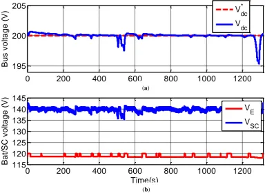
Firstly, the results under the long Arterial driving cycle are shown in Fig. 19, where the bus voltage, the voltages and the currents of battery/SC with the PBL2AC control are plotted. It can be observed that the regulation error of bus voltage is less than 4.4V despite of uncertainties. The battery voltage tends to decline due to the power depleting and the SC voltage fluctuates frequently. The SC current and the load current are shown in Fig. 19(b).
Then, the results under hybrid driving cycle including US06 cycle, UDDS cycle, NYCC cycle, HWFET cycle, WVUCITY cycle and NEDC cycle, are shown in Fig. 20. From Fig. 20(a), it can be seen that the regulation error of bus voltage is less than 3.2V. Moreover, the SC voltage varies during the charging or discharging process. The SC and the load currents are shown in Fig. 20(b).
1:
V
E,
[20 V/div]
2:
V
sc,
[20 V/div]
3:
V
dc,
[2 V/div]
1:
i
2,
[10 A/div]
2:
i
m,
[10 A/div]
(b)
Figure 19. Response of the proposed PBL2AC control under the long Alternal driving cycle. (a) battery voltage, SC voltage and bus voltage;(b) SC and load currents.
1:
V
E,
[20 V/div]
2:
V
sc,
[20 V/div]
3:
V
dc,
[2 V/div]
1:
i
2,
[10 A/div]
2:
i
m,
[10 A/div]
(b)
Figure 20. Response of the proposed PBL2AC control under the hybrid driving cycle. (a) battery voltage, SC voltage and bus voltage;(b) SC and load currents.
From these, it can be verified that with the proposed PBL2AC control, the bus voltage under comprehensive driving cycles keeps stable in spite of perturbations and driving condition change.
5. Conclusions
An L2-gain adaptive robust control based on PCHD for current tracking and voltage stability for HESS in EV is presented. A complete PCHD model containing both parameter variations and external disturbances is initially well constructed. Moreover, adaptive mechanism is adopted to estimate the parameters. Results show that the effectiveness of the proposed PBL2AC under CUDC vehicle condition can be confirmed.
Author Contributions: X.Z. Zhang conceived of the idea for the research and preformed the controller design and algorithm coding as the first author. Z. Lu performed the modeling, analysis and results tests.
Funding: This research received no external funding.
Acknowledgments: Work was supported by the National Science Foundation of China (61673164).
Conflicts of Interest:“The authors declare no conflict of interest”.
Appendix A
none.
References
1. M. Ehsani, Y. Gao, S. E Gays, and A. Emadi, Modern Electric, Hybrid Electric, and Fuel Cell Vehicle: Fundamentals, Theory, and Design, 2nd ed. Boca Raton, FL, USA: CRC Press, 2010.
3. S. Onori, L. Serrao, and G. Rizzoni, Hybrid Electric Vehicles Energy Management Strategies, 1st ed. Berlin, Germany: Springer, 2016.
4. P. Kollmeyer et al., "Optimal performance of a full scale li-ion battery and li-ion capacitor hybrid energy storage system for a plug-in hybrid vehicle," 2017 IEEE Energy Conversion Congress and Exposition (ECCE), Cincinnati, OH, 2017, pp. 572-577.
5. Y. Zhang, Z. Jiang and X. Yu, "Control Strategies for Battery/Supercapacitor Hybrid Energy Storage Systems," 2008 IEEE Energy 2030 Conference, Atlanta, GA, 2008, pp. 1-6.
6. P. Thounthong, V. Chunkag, P. Sethakul, B. Davat and M. Hinaje, "Comparative Study of Fuel-Cell Vehicle Hybridization with Battery or Supercapacitor Storage Device," IEEE Transactions on Vehicular Technology, vol. 58, no. 8, pp. 3892-3904, Oct. 2009.
7. R. Carter, A. Cruden and P. J. Hall, "Optimizing for Efficiency or Battery Life in a Battery/Supercapacitor Electric Vehicle," IEEE Transactions on Vehicular Technology, vol. 61, no. 4, pp. 1526-1533, May 2012. 8. Tang Xisheng, Qi Zhiping. Study on the ultracapacitor/battery hybrid system. Power supply
technology,2006, 30 (11): 933-936.
9. Hussain, S.; Ali, M.U.; Nengroo, S.H.; Khan, I.; Ishfaq, M.; Kim, H.-J. Semiactive Hybrid Energy Management System: A Solution for Electric Wheelchairs. Electronics, 2019, 8, 345.
10. A. Castaings, W. Lhomme, R. Trigui, A. Bouscayrol, "Comparison of energy management strategies of a battery/supercapacitors system for electric vehicle under real-time constraints", Appl. Energy, vol. 163, pp. 190-200, Feb. 2016.
11. Z. Amjadi and S. S. Williamson, "Power-Electronics-Based Solutions for Plug-in Hybrid Electric Vehicle Energy Storage and Management Systems," IEEE Transactions on Industrial Electronics, vol. 57, no. 2, pp. 608-616, Feb. 2010.
12. S. K. Kollimalla, M. K. Mishra and N. L. Narasamma, "Design and Analysis of Novel Control Strategy for Battery and Supercapacitor Storage System," IEEE Transactions on Sustainable Energy, vol. 5, no. 4, pp. 1137-1144, Oct. 2014.
13. Arboleya, P.; El-Sayed, I.; Mohamed, B.; Mayet, C. Modeling, Simulation and Analysis of On-Board Hybrid Energy Storage Systems for Railway Applications. Energies 2019, 12, 2199.
14. Zhao, H.; Guo, S.; Zhao, H. Comprehensive Performance Assessment on Various Battery Energy Storage Systems. Energies 2018, 11, 2841.
15. Martinez C M, Hu X, Cao D, et al. Energy Management in Plug-in Hybrid Electric Vehicles: Recent Progress and a Connected Vehicles Perspective. IEEE Transactions on Vehicular Technology, 2017, 66(6):4534-4549.
16. Hu, J.; Jiang, X.; Jia, M.; Zheng, Y. Energy Management Strategy for the Hybrid Energy Storage System of Pure Electric Vehicle Considering Traffic Information. Appl. Sci. 2018, 8, 1266.
17. X.Wang, H. He, F. Sun, X. Sun, and H. Tang, “Comparative study on different energy management strategies for plug-in hybrid electric vehicles,” Energies, vol. 6, no. 11, pp. 5656–5675, Oct. 2013.
18. Rafique, M.K.; Khan, S.U.; Saeed Uz Zaman, M.; Mehmood, K.K.; Haider, Z.M.; Bukhari, S.B.A.; Kim, C.-H. An Intelligent Hybrid Energy Management System for a Smart House Considering Bidirectional Power Flow and Various EV Charging Techniques. Appl. Sci.2019, 9, 1658.
19. M. Choi, S. Kim and S. Seo, "Energy Management Optimization in a Battery/Supercapacitor Hybrid Energy Storage System," IEEE Transactions on Smart Grid, vol. 3, no. 1, pp. 463-472, March 2012.
20. Z. Song et al., "Sliding-mode and Lyapunov function-based control for battery/supercapacitor hybrid energy storage system used in electric vehicles", Energy, vol. 122, pp. 601-612, Mar. 2017.
21. Mebarki N , Rekioua T , Mokrani Z , et al. “PEM fuel cell/ battery storage system supplying electric vehicle”. International Journal of Hydrogen Energy, 2017, 42(5):3417.
22. Camara M B , Gualous H , Gustin F , et al. Design and New Control of DC/DC Converters to Share Energy Between Supercapacitors and Batteries in Hybrid Vehicles. IEEE Transactions on Vehicular Technology, 2008, 57(5):2721-2735.
23. B. Wang, J. Xu, R. Wai and B. Cao, "Adaptive Sliding-Mode With Hysteresis Control Strategy for Simple Multimode Hybrid Energy Storage System in Electric Vehicles," IEEE Transactions on Industrial Electronics, vol. 64, no. 2, pp. 1404-1414, Feb. 2017.
25. Wang X , Yu D , Le Blond S , et al. A novel controller of a battery-supercapacitor hybrid energy storage system for domestic applications. Energy and Buildings, 2017, 141:167-174.
26. Xu, Q. Liu, W. Yan and W. Yang, "Adaptive Terminal Sliding Mode Control for Hybrid Energy Storage Systems of Fuel Cell, Battery and Supercapacitor," IEEE Access, vol. 7, pp. 29295-29303, 2019.
27. Xiong R , Cao J , Yu Q . Reinforcement learning-based real-time power management for hybrid energy storage system in the plug-in hybrid electric vehicle. Applied Energy, 2018, 211:538-548.
28. Dai P , Cauet, Sébastien, Coirault P . Disturbance rejection of battery/ultracapacitor hybrid energy sources. Control Engineering Practice, 2016, 54:166-175.
29. Liu J , Gao Y , Su X , et al. Disturbance-Observer-Based Control for Air Management of PEM Fuel Cell Systems via Sliding Mode Technique. IEEE Transactions on Control Systems Technology, 2018:1-10. 30. Liao, Y.; You, J.; Yang, J.; Wang, Z.; Jin, L. Disturbance-Observer-Based Model Predictive Control for
Battery Energy Storage System Modular Multilevel Converters. Energies 2018, 11, 2285.
31. F. Zhou, F. Xiao, C. Chang, Y. Shao, C. Song, "Adaptive model predictive control-based energy management for semi-active hybrid energy storage systems on electric vehicles", Energies, vol. 10, no. 7, pp. 1063, 2017.
32. Q. Zhang, W. W. Deng, G. Li, "Stochastic control of predictive power management for battery/supercapacitor hybrid energy storage systems of electric vehicles", IEEE Trans. Ind. Informat., vol. 14, no. 7, pp. 3023-3030, Jul. 2018.
33. van der Schaft A J, Maschke B M. The Hamiltonian formulation of energy conserving physical systems with external ports. Archive f¨ur Elektronik und Ubertragungstechnik¨ ,1995, 49: 362−371.
34. Wang Y Z. Generalized Controlled Hamiltonian Systems: Realization, Control and Applications. Beijing: Science Press, 2007 (in Chinese).
35. M. Hilairet, M. Ghanes, O. Béthoux, V. Tanasa, J-P. Barbot, D. Normand-Cyrot. A passivity-based controller for coordination of converters in a fuel cell system, Control Engineering Practice, vol. 21, no. 8, pp. 1097-1109, 2013.
36. Ren, F. Liu and X. Jiao, "Speed sensorless control for wind turbine systems based on Hamiltonian model observer," Proceedings of the 30th Chinese Control Conference, Yantai, 2011, pp. 584-588.
37. Yin Zhonggang, Ding Huchen, Zhong Yanru, Liu Jing. Passivity-Based Control Method of Induction Motors Based on Port-Controlled Hamiltonian with Dissipation (PCHD) Model with Flexible Damping. Transactions of China Electrotechnical Society, vol.29, no. 8, 2014(in Chinese).
38. Wang Y Z, Feng G, Cheng D Z, Liu Y Z. Adaptive L2-disturbance attenuation control of multi-machine power systems with SMES units. Automatica, 2006, 42(7): 1121−1132.
39. M. Ryalat and D. S. Laila, "A Robust IDA-PBC Approach for Handling Uncertainties in Underactuated Mechanical Systems," IEEE Transactions on Automatic Control, vol. 63, no. 10, pp. 3495-3502, Oct. 2018. 40. Ortega R, van der Schaft A J, Maschke B, Escobar G. Interconnection and damping assignment
passivity-based control of port-controlled Hamiltonian systems. Automatica, 2002, 38(4): 585−596
41. Zhang M , Ortega R , Liu Z , et al. A new family of interconnection and damping assignment passivity-based controllers. International Journal of Robust and Nonlinear Control, 2016.
42. Tiezhou Wu, Zhihao Cheng, Jiasheng Zhang, Zhangqing He. A PCH strong tracking control strategy for power coordinated allocation of Li-SC HESS. Microelectronics Reliability, vol. 88–90, pp. 1261-1267, 2018. 43. A. Benmouna, M. Becherif, J. Chen, H. Chen, D. Depernet. Interconnection and damping assignment
passivity based control for fuel cell and battery vehicle: Simulation and experimentation. International Journal of Hydrogen Energy,vol. 44, no. 39, pp. 22467-22477,2019.
44. X. Zhang, Y. Wang, G. Liu and X. Yuan. Robust Regenerative Charging Control Based on T–S Fuzzy Sliding-Mode Approach for Advanced Electric Vehicle. IEEE Transactions on Transportation Electrification, vol. 2, no. 1, pp. 52-65, 2016.