EEG Based Gesture Mimicking by An Artificial Limb
Using Cascade-Correlation Learning Architecture
Sriparna Saha, Amit Konar, Anuradha Saha,
Arup Kumar Sadhu
Electronics & Tele-Communication Engineering Department
Jadavpur University, Kolkata, India [email protected], [email protected],
{anuradha.nsec, arup.kaajal}@gmail.com
Bonny Banerjee
#, Atulya K. Nagar
* #Electrical & Computer Engineering Department #The University of Memphis, United States of America*Mathematics and Computer Science Department *Liverpool Hope University, United Kingdom #[email protected], *[email protected]
Abstract—Patients with prosthesis defects find it is very difficult to perform day-to-day basic tasks which involve employment of their limbs. This motivates us to develop a system where an artificial limb is employed to mimic the arm gestures of the patients for assisting them. Towards developing this system, we have taken the help from the electroencephalography (EEG) signals acquired from the brain of the patients to build a bypass network (BPN) to direct the artificial limb. Since difficulties are already present in the arm movements of the patients (here subjects), thus only gestures of those subjects are not sufficient to build the proposed system. This research finds tremendous applications in rehabilitative aid for the disable persons. To concretize our goal we have developed an experimental setup, where the target subject (for training phase healthy subjects are taken into account) is asked to catch a ball while his/her brain (occipital, parietal and motor cortex) signals using EEG acquisition device and body gestures using Kinect sensor are simultaneously acquired. These data are mapped using four cascade-correlation learning architecture (CCLA) to train artificial limb (we have used Jaco robot arm) to move accordingly. Utilizing the mapping results obtained from these four CCLAs, a BPN is developed. When a rehabilitative patient is unable to catch the ball, then in that scenario, the artificial limb is helpful for assisting the patient to catch the ball with a high accuracy of 85.65%. The proposed system can be implemented not only for ball catching experiment but also in several applications where an artificial limb needs to perform a locomotive task based on EEG and body gesture.
Keywords—human machine interface; gesture mimicking; rehabilitation; electroencephalography; Kinect sensor; Jaco robot arm; cascade- correlation learning architecture
I. INTRODUCTION
Gestures constitute an important medium for human beings to interact and communicate with the surroundings. Gestures are expressive body movements, involving the face and arms in majority of the cases. Gesture recognition i.e., interpretation of the different human gestures is a very important aspect of human computer interaction. It enables humans to efficiently communicate with machines using only sign language.
Suppose a subject wants to bring a glass of water from a nearby table to drink, but unfortunately he/she is suffering
from prosthesis damages in the arms, then it is not feasible for the patient (here subject) to bring the glass using his/her arms [1]. Similar problem is faced by the subject when he/she tries to do the same task having difficulties in the parietal region of the brain. But in the above two scenarios we can place an electroencephalography (EEG) acquisition device to record the occipital data of that subject while the subject is looking at that glass, and based on the EEG signal, a robotic arm (artificial limb) is employed to grip the glass. This is just a simple example of how to control an artificial limb using human brain signals, where the position of the target object (i.e., the glass) is stationary. This motivates us to implement our research work in the scenario where the position of the target is not fixed with respect to time. Thus we have outlined the work in such a manner where two subjects are involved, one is our target subject wearing a EEG sensor and concurrently whose motion is captured by a motion sensing device, Kinect and another subject is just throwing a ball towards the first subject. We can use this technique in several other cases which involves artificial limb to do some locomotive works based on brain signal and human gestures. The work finds tremendous importance in rehabilitative application areas where a subject is suffering from difficulties in parietal and/or motor cortex region(s) and due to this, prosthesis problems are faced by the subject.
Multimodal interactions including speech, gesture etc. is carried out by Csapo et al. with Nao humanoid robot for HMI applications [7].
The prediction of hand movements acquired using Kinect sensor from EEG signals obtained from respective parts of the brain is done by Datta et al. [8] using principal component analysis (PCA) for feature selection and regression analysis using back propagation neural network (BPNN). But the former paper does not train any robot to perform the task in case the subject is unable to do the same. Frisoli et al. [9] designed a system based on human gaze, where analysis on Kinetic data and EEG signals is done for neuro-rehabilitation of patients. The outcome of the former work is to direct a robotic upper limb exoskeleton based on the acquired data in real-time. In [10], Roy et al. has controlled not only position, but also velocity of an exoskeleton using state feedback PI controller. EEG signals containing the right motor intention, as captured from the human brain, is classified using Quadratic discriminant analysis (QDA) classifier and is fed to the controller for accurate movement. Another interesting application of Kinect sensor along with EEG signal is to improve the life style of patients suffering from motor/communication impairments by training them through gaming technology [11]. The depth segmentation and RGB data obtained from Kinect sensor as well as EEG features including mean absolute value and variance unbiased estimator are utilized to classify hand grasping during gaming activity in [11]. Similar kind of experiment for tracking self-paced hand opening/closing has been carried out on stroke patients by using EMG sensors along with EEG and Kinect sensors [12].
To implement our novel system of gesture mimicking based on EEG signals for artificial limb movement, we require three devices, namely EEG acquisition device [2]–[4], [8]–[12], Kinect sensor [5]–[9], [11]–[14] and Jaco robot arm [1]–[4], [9]. For healthy subjects, when a ball is thrown, then they are instructed to catch the ball. The EEG signals from occipital, parietal and motor cortex regions are acquired using EEG acquisition device as well as the skeleton of the target subject is obtained using Kinect sensor while catching the ball. Now three mappings are done between occipital-parietal, parietal-motor cortex and parietal-motor cortex-skeleton using four cascade-correlation learning architectures (CCLA) [15] in the first training phase. The order of the mappings are in that fashion because first the subject sees the ball coming towards him/her using occipital region, then the parietal region plans how to catch the ball. Based on the planning the motor cortex region instructs the arms of the subjects accordingly. Upon getting these signals, the subject tries to catch the ball. For the next training phase, CCLA is employed to map between skeleton and displacements of the Jaco arm, such that in the absence of the parietal and motor cortex signals, the artificial limb is able to catch the ball. We have used CCLA as it has much better performance in terms of weight adaptation and randomness with comparison with BPNN. After the completion of the training phase, we have tested our proposed system for rehabilitative patients with damage in parietal and/or motor cortex regions. Former subjects due to disability are unable to plan and execute the movements of the hands, thus to provide assistance, Jaco robot arm is orchestrated to catch the ball. Here
we have created a bypass network (BPN) using the data from occipital region of the patient.
The subsequent sections of this paper are organized as follows. Section II provides the technical overview of the proposed work providing details of the training and testing phases. The methodologies used are described in section III. The elaboration of the experimental results is given in section IV while section V concludes the proposed system.
II.TECHNICAL OVERVIEW
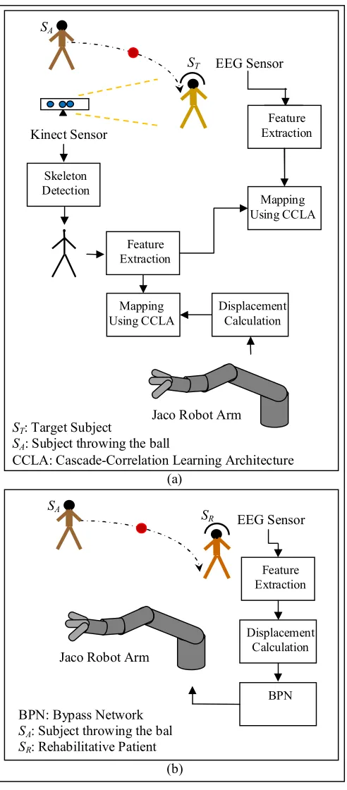
Fig. 1 depicts the schematic diagram of our proposed system. The system utilizes three devices, namely
21-channel EEG signal acquisition device
(manufactured by Nihon Kohden) [2]–[4], [8]–[12] to record the physiological signals from the brain.
Kinect 360 sensor [5]–[9], [11]–[14] (manufactured by Microsoft) to capture the body gesture of the subject in skeletal view by representing the body with twenty Cartesian joint co-ordinates in three dimensional space (3D).
Jaco robot arm [1]–[4], [9] (manufactured by Kinova) is manipulated based on the information obtained from EEG signal acquisition device and Kinect sensor. The system consists of two major parts: training phase and testing phase.
A. Training Phase
This phase consists of the steps needed to train the artificial limb. This phase is bifurcated into two parts:
1) Training phase 1 (TP1):
We have implemented the proposed system in such a fashion that the subject under consideration (ST) is asked to
catch the ball thrown by a separate subject (SA). Now the target
subject is wearing an EEG sensor [2]–[4], [8]–[12] to record physiological signals from the brain. Also his/her body gestures are captured by the Microsoft’s Kinect sensor [5]–[9], [11]–[14]. When the target subject notices a ball coming towards him/her then the occipital region in the brain gets activated. Now to catch the ball the parietal region of the brain planes how the body of the subject needs to be bent to catch that ball. Based on that signal from the parietal part of the brain, the motor cortex region instructs the arms of the subject to act accordingly. How the subject positioned his/her body to catch the ball, that gesture is accumulated by the Kinect sensor.
To achieve this three mappings are done between
occipital signals (OSTPT) and parietal signals (PSTPT) to
adapt weight matrix W1 using CCLA1
parietal signals (PSTPT) and motor cortex signal (MSTPT)
to adapt weight matrix W2 using CCLA2
motor cortex signal (MSTPT) and Kinetic data (KDTPT) to
adapt weight matrix W3 using CCLA3
Fig. 1. Complete view of the proposed system for rehabilitative applications, (a) training phase, (b) testing phase.
2) Training phase 2 (TP2):
Now the second part deals how the end effector (i.e., gripper) of the Jaco robot arm, which needs to be placed in the exact position of the palm of the target subject, such that the Jaco robot arm [1]–[4], [9] is able to catch the ball instead of
the target subject. For this purpose Kinetic data for the required gesture (KDTPT) and mapped with displacement of Jaco robot
arm (DJTPT) using CCLA4 [15], [16] and after successful run of
CCLA the weight matrix becomes W4. This architecture is
given in Fig. 3.
Fig. 2. Architecture of training phase 1.
Fig. 3. Architecture of training phase 2.
B. Testing phase (EP)
After training the system with the above process, a BPN is formed such that when a ball is thrown to a rehabilitative patient (SR) suffering from damage in the parietal and/or motor
cortex region(s), then based on the signals obtained from occipital region (OSEPR), Jaco robot (DJEPR) is instructed. Thus
trained weight matrices (W1 to W4) are taken into account to
construct a BPN. This network is termed as bypass network as here displacement of Jaco robot is possible by bypassing the signals from parietal, motor cortex regions and the Kinetic data as shown in Fig. 4.
III. METHOLOGIES USED
This section illustrates the procedure for feature extraction (FE) and mapping employing CCLA.
A. FE for EEG Signals (OS, PS and MS)
Features of EEG signal are represented as the basic primitives of the signal itself. In the present paper, the significant information are extracted using Power spectral (a)
ST
SA SA
SR
(b) Kinect Sensor
Skeleton Detection
EEG Sensor
Feature Extraction
Feature Extraction
Mapping Using CCLA
Jaco Robot Arm
Displacement Calculation Mapping
Using CCLA
Jaco Robot Arm
BPN: Bypass Network SA: Subject throwing the ball SR: Rehabilitative Patient
EEG Sensor
Feature Extraction
BPN Displacement
Calculation
ST: Target Subject
SA: Subject throwing the ball
CCLA: Cascade-Correlation Learning Architecture
W4
DJTPT CCLA4
CCLA: Cascade-Correlation Learning Architecture, W: Adapted Weight Matrix, TP: Training Phase, T: Target Subject, 4: Index Number
KDTPT
CCLA: Cascade-Correlation Learning Architecture, W: Adapted Weight Matrices, TP: Training Phase,
density (PSD) from the filtered EEG signal, which contains signal power distribution in the occipital, parietal and motor cortex lobes. Mathematically, PSD is defined as a Fourier Transform of the autocorrelation sequence of the time series, which is given below.
2 1 2
( )
( )
t ft tEEG f
eeg t e
dt
(1)2
2 1
|| ( ) ||
( ) 2
( )
EEG f PSD f
t t
(2)
Fig. 4. Architecture of testing phase.
After FE, it is important to select the most significant EEG features without hampering the classification accuracy, if the feature dimension is high. PSD, being a high dimensional feature extractor, does not contain all important features. Therefore, we apply standard principal component analysis (PCA) to select a fewer significant features from a large pool of features to train the neural network.
B. FE for Kinectic Data (KD)
As already stated, the Kinect sensor can represent a human body using twenty body joint co-ordinates (JC), but for this proposed work, the changes occur in the arms along with upper body (except head) co-ordinates have the major impact while catching a ball. Also the transitions in those joints from initial state (when the subject first sees the ball coming) to goal state (when the subject is able to catch the ball) are irreverent as the degrees of freedom (DOF) for human arm (dofH=27 [17]) and
Jaco robot arm (dofJ=7 including gripper [1]) are not
comparable. Thus we are only concerned about the difference between the joint co-ordinates between initial state (ISKD) and
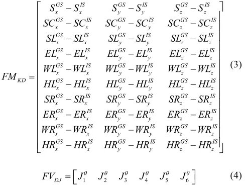
goal state (GSKD). The required joints in 3D (x, y and z) are spine (S), shoulder center (SC), shoulder left (SL), elbow left (EL), wrist left (WL), hand left (HL), shoulder right (SR), elbow right (ER), wrist right (WR) and hand right (HR). The extracted feature matrix (FMKD) is given in (3).
C. FE for Displacements of Jaco Robot Arm (DJ)
Jaco robot arm is manufactured by Kinova and is a robotic manipulator with a three fingered gripper to grip an object (here ball). The arm has 7 degree of freedom (DOF) [1] with a maximum reach of 90 cm and has maximum linear speed of 20 cm/s. For displacement of Jaco robot (DJ) from initial state
(ISDJ) to goal state (GSDJ), we have to specify the following feature vector FVDJ using (4).
GS IS GS IS GS IS
x x y y z z
GS IS GS IS GS IS
x x y y z z
GS IS GS IS GS IS
x x y y z z
GS IS GS IS GS IS
x x y y z z
GS IS GS IS GS IS
x x y y z z
KD GS IS GS IS GS IS
x x y y z z
x
S S S S S S
SC SC SC SC SC SC
SL SL SL SL SL SL
EL EL EL EL EL EL
WL WL WL WL WL WL
FM
HL HL HL HL HL HL
SR
GS IS GS IS GS IS
x y y z z
GS IS GS IS GS IS
x x y y z z
GS IS GS IS GS IS
x x y y z z
GS IS GS IS GS IS
x x y y z z
SR SR SR SR SR
ER ER ER ER ER ER
WR WR WR WR WR WR
HR HR HR HR HR HR
(3)
1 2 3 4 5 6
DJ
FV J J J J J J
(4)
where, 1 to 6 indicates the joint (J) number of the Jaco robot arm and θ denotes the desired angle of that respective joint needs to be rotated to act accordingly. The value of θ can be positive or negative based on whether it is anticlockwise or clockwise respectively.
D. Mapping Using Cascade-Correlation Learning Architecture (CCLA)
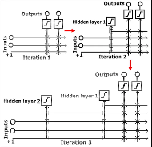
In the view of real-world problem, computational cost is the main bottleneck of the existing artificial neural network based learning algorithm (e.g., BPNN). The former limitation is overcome by employing the CCLA [15], which is an artificial neural network based algorithm, begins with minimum input and output nodes. Gradually the network trains and adds hidden layers to create a multi-layered neural network. All the hidden neurons have fixed weight (square connection) in the input side as shown in Fig. 5 and only the output side weights (crossed connections) are trained. The bias is fixed at +1. Unlike back-propagation [8], the CCLA trains the weights directly connected to the outputs, which results in incredible speed-up as compared to the BPNN. Also CCLA creates promising high-order feature detectors. The CCLA is a twofold idea:
One is the addition of cascade architecture to add fixed hidden layer one at a time to the network.
Another is the learning algorithm to install a hidden layer with a symmetric sigmoidal activation function such that the residual error signal is minimized which in turn maximizes the correlation between the new network's output.
To train the weights directly connected to the output neurons, a single-layered learning algorithm (e.g., Widrow-Hoff or "delta" rule, perceptron learning and resilient propagation (RPROP) algorithm [16]) is employed. In this paper, RPROP is selected for training.
BPN: Bypass Network, W: Trained Weight Matrix, EP: Testing Phase, R: Rehabilitative Patient, 1-4: Index Number
W1-W4
DJEPR BPN
New hidden layer is created by selecting a candidate unit (e.g., sigmoidal function, Gaussian function, radial basis function, etc.), which can be connected to all the pre-existing input, output and hidden layers. A number of passes is done to adjust and fix the input weights of the candidate unit. Finally the output of the candidate unit is connected to the network.
Fig. 5. Block diadram of cascade-correlation learning architecture (square indicates fixed connection and crossed connections are trained).
The input weights of the candidate unit are adjusted with an aim to maximize the sum over all the outputs covariance given in (5),
,
| ( )( ) |
v p p o
o p
C
V V E E (5)where, V be the candidate unit's value, Eo,p be the residual
output error observed at output unit o in the pth training pattern and V E, oare the average values of V, Eo respectively over all
the training pattern. In CCLA, like BPNN v i C w
is computed
in (6) to maximize Cv where, wi is the ith candidate units
incoming weight.
/
, ,
,
( )
v
o p o o p i p p o
i C
E E f I
w
(6)
where, σo be the correlation between the candidate value
and output, fp/ be the first derivative of the candidate unit's
activation function with respect to the sum of its inputs for pattern p and Ii,p refers the input revived by the candidate unit
from ith candidate for pattern p. A gradient descent to maximize
Cv follows after computing v i C w
for each incoming
connection. The new candidate unit is connected as an fixed and active part of the network as Cv stops improving. It is
possible to employ a set of candidate units with randomly initialized input weights, instead of employing single candidate unit to install hidden layers in the network. When a set of candidate units are employed, they receive the same input, residual error and output, because the candidate units' outputs are not connected to the active network. Employing a set of candidate units is advantagious in two ways:
It reduces the chance of installing a useless neuron, which got stuck during training.
It can speed-up the training because of the simultaneous wide exploration of the weight-space.
IV. EXPERIMENTAL RESULTS
This section elaborates the experimental setup along with subject details, signals analysis from EEG and Kinect sensors. In addition, subsequent movement of the Jaco robot arm is shown. The section also shows the performance study of the proposed system with other existing literatures considering accuracy, precision, sensitivity, specificity and F1 score as the performance metrics and statistical test.
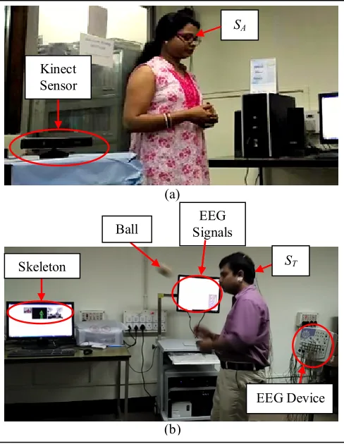
A. Setup
The experiment has been performed at Artificial Intelligence Lab, Jadavpur University, where the framework includes a Kinect sensor (Fig. 6 (a)) and a 21-channel wired EEG device (Fig. 6 (b)). It has also been obvious from Fig. 7(b) that Kinect data and EEG signals are recorded on two different computers with 8 GB RAM with CPU clock of 3.4 GHz.
B. Data Acquisition Using EEG and Kinect Sensors
We have created 3 datasets with 24 healthy subjects (15 men and 9 women). In each dataset, equal number of subjects are taken where gender ratio is 5:3 and for these 3 datasets the age groups are (25±2yrs), (28±2yrs) and (30±2yrs) in the training experiments. Among 24, 12 subjects (6 men and 6 women) have been participated for the testing sessions.
1) Using EEG Sensors
In this experiment, EEG signals from electrode positions: P3, P4, Pz, C3, C4, Cz, O1 and O2 are recorded by using a 21-channel stand-alone EEG device having a sampling rate of 200 Hz and resolution of 100µV. Each subject is instructed to throw the ball to the opponent from eleven different positions.
Fig. 6. Total setup of the proposed work for rehabilitative applications: (a) Towards SA end, (b) Towards SR end.
Fig. 7. Raw EEG signals recorded from O1 and O2 electrodes during 5th and
6th instances.
There is a close parity in signal patterns recorded from the same set of electrodes for two different instances.
For each brain lobe (i.e., occipital, parietal and motor cortex), changes in signal pattern from their usual nature near about the same samples ensure the correlation between three brain lobes for a particular given instance.
Changes in EEG pattern in different lobes validate the well-known EEG signal modalities. From Fig. 7 and 8, sudden positive rise in signal amplitude ensures the liberation of P300 modality from occipital and parietal lobes, whereas from Fig. 9 de-synchronization of EEG signal from the usual pattern at the start of motor action and again synchronized with the original pattern after completion of the motor activity ensures the association of event-related desynchronization/synchronization (ERD/ERS) modality during movement-related tasks.
Fig. 8. Raw EEG signals recorded from P3, P4 and Pz electrodes during 5th
and 6th instances.
Fig. 9. Raw EEG signals recorded from C3, C4 and Cz electrodes during 5th
and 6th instances.
Since, the raw EEG signals contain noise and eye-blinking artifacts, following two steps have been performed to make the EEG signal artifact-free. First, we designed a band pass filter having suitable pass band frequencies to filter the line noise. Here, we use a Chebyshev type 2 filter having variable pass band frequency. For visual signal, pass band of the above filter is selected from 3 to 13 Hz in order to pass necessary information involved in theta (3-7 Hz) and alpha (7-13 Hz) band. For motor imagery and execution, pass band frequency is so chosen that it includes sensorimotor (7-13 Hz) and beta (13-(b)
(b) (a)
SA
Kinect Sensor
Skeleton
EEG Device EEG
Signals
ST
30 Hz) rhythm. Second, we perform independent component analysis (ICA) [18] to remove eye-blinking artifacts from the evaluated EEG signals. In this technique, the scalp-components having artifacts are rejected and the remaining artifact-free components are selected.
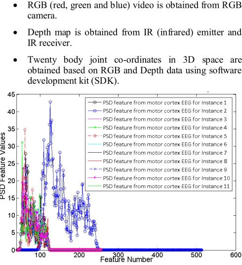
Fig. 10.PSD features extracted from occipital lobe during eleven instances.
Fig. 11.PSD features extracted from parietal lobe during eleven instances.
Once pre-processing of EEG signal is done, features are extracted from the filtered EEG samples taken at eleven experimental instances. Fig. 10-12 present PSD feature discrimination of EEG signals recorded from occipital, parietal and motor cortex regions respectively during those instances. It is important to note from Fig. 10-12 that although PSD extracts more than several hundreds of features from each lobe, all features do not have significant values. For example, beyond 80th feature (for occipital EEG) and beyond 260th feature (for parietal and motor cortex EEG), we get redundant features. Another interesting fact is that for three brain regions, almost all instances have overlapped features except for instance 2 and hence a few features have capability to discriminate all eleven instances. To overcome this problem, we apply standard PCA algorithm [8] which selects 12 features that correctly discriminate all eleven instances.
2) Using Kinect Sensor
The Kinect sensor basically has three sensors responsible for three types of outputs.
RGB (red, green and blue) video is obtained from RGB camera.
Depth map is obtained from IR (infrared) emitter and IR receiver.
Twenty body joint co-ordinates in 3D space are obtained based on RGB and Depth data using software development kit (SDK).
Fig. 12.PSD features extracted from motor cortex during eleven instances.
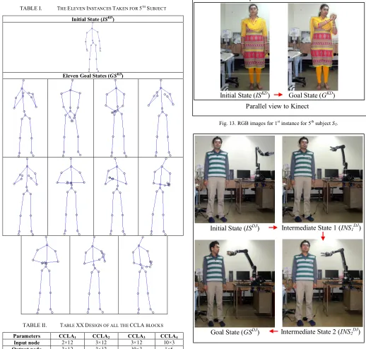
The skeletons obtained for eleven instances are shown in Table I. The RGB images taken by a separate camera placed perpendicular and parallel to Kinect to provide better visualization for the 1st instance for 5th subject is shown in Fig. 13. This figure elaborates how the gesture for subject ST
changes through ISKD→ INS1KD→ INS2KD→ INS3KD→ GSKD.
The corresponding FMKD obtained is given in (7).
0.0094 0.0755 0.0498
0.0175 0.0515 0.0179
0.0177 0.0598 0.0548
0.0530 0.0332 0.0296
0.1177 0.4650 0.0850
0.1079 0.5912 0.1334
0.0023 0.0668 0.0471
0.0061 0.0070 0.1010
0.09404 0.4986 0.1082
0.0945 0.6190 0
KD FM
.1615
(7)
C. Parameters Settings for CCLA
Table II shows the design of CCLA. The parameters set for RPROP [16] are Δmin=0.0001, Δini=0.01, Δmax=0.5, η =0.5
D. Displacement of Jaco Robot
The Jaco robot arm including gripper is suitable for a person with disability of the parietal and/or motor cortex lobes. It can be attached to a wheelchair or somewhere else to assist the disabled person [9]. The RGB images taken by a separate camera placed parallel to Kinect (as Kinect’s RGB camera has only 8-bit VGA resolution) for better view and picture quality for the 1st instance for 10th subject is shown in Fig. 14. This figure shows how the Jaco moves for subject SR changes
through ISDJ → INS1DJ → INS2DJ → GSDJ. The exact
movements occur in different joints for Jaco whole accommodating the desired movement.
TABLE I. THE ELEVEN INSTANCES TAKEN FOR 5TH SUBJECT
Initial State (ISKD)
Eleven Goal States (GSKD)
TABLE II. TABLE XXDESIGN OF ALL THE CCLA BLOCKS
Parameters CCLA1 CCLA2 CCLA3 CCLA4
Input node 2×12 3×12 3×12 10×3
Output node 3×12 3×12 10×3 1×6
Passes 500 800 750 400
Candidate units 40 60 50 30
Fig. 13.RGB images for 1st instance for 5th subject ST.
Fig. 14.RGB images for 1st instance for 10th rehabilitative patient SR.
Intermediate State 2 (INS2DJ)
Intermediate State 1 (INS1DJ)
Goal State (GSDJ) Initial State (ISDJ)
Intermediate State 3 (INS3KD)
Intermediate State 2 (INS2KD)
Intermediate State 1 (INS1KD)
Parallel view to Kinect
Initial State (ISKD) Goal State (GKD)
E. Performance Analysis
We have compared CCLA performances with BPNN [8], feed forward neural network (FFNN) [19], adaptive neural fuzzy inference (ANFI) [3], ensemble classifier using binary tree (ECBT) [20], linear support vector machine (LSVM) [20], support vector machine with radial basis function (RBFSVM) [21], AdaBoost-support vector (ASVM) [4], k-nearest neighbor (kNN) using the metrics including accuracy, precision, sensitivity, specificity and F1 score. The average results for 3 datasets for these metrics are given in Table III.
TABLE III. COMPARISON OF PROPOSED WORK WITH EXISTING LITERATURES
Algorithms Accuracy Precision Sensitivity Specificity F1 Score CCLA 85.65 84.74 82.52 85.02 86.83
BPNN 78.92 77.47 79.91 80.22 78.30
FFNN 75.72 73.07 74.18 75.00 72.93
ANFI 81.46 78.16 81.08 80.66 81.17
ECBT 69.49 71.08 73.12 70.92 69.74
LSVM 56.84 57.86 57.29 59.49 58.71
RBFSVM 69.05 70.75 69.27 70.71 71.98
ASVM 71.03 70.89 70.93 69.22 71.71
kNN 66.57 66.75 67.52 69.31 65.68
All the experiments are performed with Intel(R) core(TM) i7-4790 processor and 8 GB of DDR2-memory. For the training stage, the codes are written in Matlab R2012b and Microsoft Visual Studio 2010 version is employed to test the experiments in real-time with Jaco robot arm.
F. Friedman’s Statistical Test
The best of all the c algorithms, i.e., 1≤c≤C, is given rank 1 and the worst is given rank D. The average ranking obtained by the cth algorithm over all d (1≤d≤D) datasets is Rc.
2
2 2
1
12
(
1)
(
1)
4
C
c c
D
C C
R
C C
(8)We have done this analysis based on accuracy values obtained for all the algorithms. Here, D=3 and C=9. In Table IV, it is shown that the null hypothesis has been rejected, as χ2F=23.64 is greater than 15.51, the critical value of χ2
distribution for C−1=8 DOF with 95% accuracy.
TABLE IV. PERFORMANCE ANALYSIS USING FRIEDMAN’S TEST
Algorithm Dataset 1 Dataset 2 Dataset 3 Rc χ2
CCLA 1 1 1 1.00
23.64
BPNN 3 2 3 2.67
FFNN 5 4 4 4.33
ANFI 2 3 2 2.33
ECBT 6 6 6 6.00
LSVM 9 9 9 9.00
RBFSVM 7 7 7 7.00
ASVM 4 5 5 4.67
kNN 8 8 8 8.00
V.CONCLUSION
The proposed work implements a novel technique for mimicking arm gesture by an artificial limb based on signals from EEG sensor. In the first training phase, four mappings are done between three (occipital, parietal and motor cortex) brain signals and skeleton obtained from Kinect sensor. In the next training phase, another mapping is done to direct the Jaco robot based on the skeleton. All the four mapping are done using dedicated CCLA. In the testing phase, a BPN is created to employ the Jaco robot arm to assist a patient with prosthesis damages due to parietal and/or motor cortex region(s) for providing rehabilitative help. This system has huge scope in the development of rehabilitative aids for several tasks that needs to be performed daily basis. The system shows an accuracy of 85.65% which is very high in this concern domain.
The novelty of the proposed system lies in the fact that it uses CCLA as this network shows much better performance dealing with the weight adaptation and randomness when compare with other neural networks including BPNN. For the real time implementation of the system, a proper selection of network has vital importance.
ACKNOWLEDGMENT
The research work is supported by the University Grants Commission, India, University with Potential for Excellence Program (Phase II) in Cognitive Science, Jadavpur University and University Grants Commission (UGC) and Council of Scientific and Industrial Research (CSIR) for providing fellowship to the authors.
REFERENCES
[1] V. Maheu, J. Frappier, P. S. Archambault, and F. Routhier, “Evaluation of the JACO robotic arm: Clinico-economic study for powered wheelchair users with upper-extremity disabilities,” in Rehabilitation Robotics (ICORR), 2011 IEEE International Conference on, 2011, pp. 1–5.
[2] L. Bougrain, O. Rochel, O. Boussaton, and L. Havet, “From the decoding of cortical activities to the control of a JACO robotic arm: a whole processing chain,” arXiv Prepr. arXiv1212.0083, 2012.
[3] S. Bhattacharyya, D. Basu, A. Konar, and D. N. Tibarewala, “Interval type-2 fuzzy logic based multiclass ANFIS algorithm for real-time EEG based movement control of a robot arm,” Rob. Auton. Syst., vol. 68, pp. 104–115, 2015.
[4] S. Bhattacharyya, A. Konar, and D. N. Tibarewala, “Motor imagery, P300 and error-related EEG-based robot arm movement control for rehabilitation purpose,” Med. Biol. Eng. Comput., vol. 52, no. 12, pp. 1007–1017, 2014.
[5] B. Wang, C. Yang, and Q. Xie, “Human-machine interfaces based on EMG and Kinect applied to teleoperation of a mobile humanoid robot,” in Intelligent Control and Automation (WCICA), 2012 10th World Congress on, 2012, pp. 3903–3908.
[6] G. Du and P. Zhang, “Markerless human–robot interface for dual robot manipulators using Kinect sensor,” Robot. Comput. Integr. Manuf., vol. 30, no. 2, pp. 150–159, 2014.
[7] A. Csapo, E. Gilmartin, J. Grizou, J. Han, R. Meena, D. Anastasiou, K. Jokinen, and G. Wilcock, “Multimodal conversational interaction with a humanoid robot,” in Cognitive Infocommunications (CogInfoCom), 2012 IEEE 3rd International Conference on, 2012, pp. 667–672. [8] S. Datta, A. Khasnobish, A. Konar, D. N. Tibarewala, and A. K. Nagar,
inspired task using neural networks,” Neural Networks (IJCNN), 2014 International Joint Conference on. pp. 3371–3378, 2014.
[9] A. Frisoli, C. Loconsole, D. Leonardis, F. Banno, M. Barsotti, C. Chisari, and M. Bergamasco, “A new gaze-BCI-driven control of an upper limb exoskeleton for rehabilitation in real-world tasks,” Syst. Man, Cybern. Part C Appl. Rev. IEEE Trans., vol. 42, no. 6, pp. 1169– 1179, 2012.
[10] R. Roy, A. Konar, and D. N. Tibarewala, “EEG driven artificial limb control using state feedback PI controller,” in Electrical, Electronics and Computer Science (SCEECS), 2012 IEEE Students’ Conference on, 2012, pp. 1–5.
[11] N. A. da Silva, R. Maximiano, and H. A. Ferreira, “Hybrid Brain Computer Interface Based on Gaming Technology: An Approach with Emotiv EEG and Microsoft Kinect,” in XIII Mediterranean Conference on Medical and Biological Engineering and Computing 2013, 2014, pp. 1655–1658.
[12] R. Scherer, J. Wagner, G. Moitzi, and G. Muller-Putz, “Kinect-based detection of self-paced hand movements: enhancing functional brain mapping paradigms,” in Engineering in Medicine and Biology Society (EMBC), 2012 Annual International Conference of the IEEE, 2012, pp. 4748–4751.
[13] I. Siradjuddin, L. Behera, T. M. McGinnity, and S. Coleman, “A position based visual tracking system for a 7 DOF robot manipulator using a Kinect camera,” in Neural Networks (IJCNN), The 2012 International Joint Conference on, 2012, pp. 1–7.
[14] G. Csaba, L. Somlyai, and Z. Vámossy, “Differences between Kinect and structured lighting sensor in robot navigation,” in Applied Machine Intelligence and Informatics (SAMI), 2012 IEEE 10th International Symposium on, 2012, pp. 85–90.
[15] S. E. Fahlman and C. Lebiere, “The cascade-correlation learning architecture,” 1989.
[16] M. Riedmiller and H. Braun, “A direct adaptive method for faster backpropagation learning: The RPROP algorithm,” in Neural Networks, 1993., IEEE International Conference on, 1993, pp. 586–591.
[17] G. ElKoura and K. Singh, “Handrix: animating the human hand,” in
Proceedings of the 2003 ACM SIGGRAPH/Eurographics symposium on Computer animation, 2003, pp. 110–119.
[18] T.-W. Lee, Independent component analysis. Springer, 1998.
[19] M. Leena, K. Srinivasa Rao, and B. Yegnanarayana, “Neural network classifiers for language identification using phonotactic and prosodic features,” in Intelligent Sensing and Information Processing, 2005. Proceedings of 2005 International Conference on, 2005, pp. 404–408. [20] S. Saha, S. Datta, A. Konar, and R. Janarthanan, “A study on emotion
recognition from body gestures using Kinect sensor,” in
Communications and Signal Processing (ICCSP), 2014 International Conference on, 2014, pp. 56–60.