R E S E A R C H
Open Access
DCL 2.0: modular and reusable
specification of architectural constraints
Henrique Rocha
1*, Rafael Serapilha Durelli
2, Ricardo Terra
2, Sândalo Bessa
1and Marco Túlio Valente
1Abstract
Background: Due to the abstract nature of software architecture concepts, ensuring the correct implementation of architectural decisions is not a trivial task. Divergences between the planned architecture and source code may occur in the early stages of the software development, which denotes a phenomenon known as software architecture erosion. Architectural conformance checking techniques have been proposed to tackle the problem of divergences between the planned architecture and source code. Among such techniques, we can note the DCL (dependency constraint language), which is a domain-specific language that has interesting results in architectural conformance contexts. However, the current version of DCL has some limitations, such as lack of modularity and low degree of reuse, which may prevent its adoption in real software development scenarios. In this article, we extend DCL with a reusable, modular, and hierarchical specification.
Method: We propose and evaluate DCL 2.0—an extension of the original DCL—and its tool in a real-world development scenario of a large system used by a government branch of Minas Gerais, Brazil.
Result: We were able to detect 771 architectural violations where 74% of them could only be detected due to the new violation types proposed in DCL 2.0.
Conclusion: By using DCL 2.0 herein presented, it was possible to conclude the following: (i) DCL 2.0 proved importance in helping the development team consistently address violations, and (ii) after using DCL 2.0 for months, the number of architectural violations being committed into the system branches was reduced to zero. Therefore, we argue that DCL 2.0 can have a positive impact on the architectural conformance of systems.
Keywords: Architecture conformance, Hierarchical specification, Architecture reuse, Structural violation
Introduction
Software architecture is commonly considered a set of decisions and conventions that determine how to build a system, i.e., the architecture states the software’s funda-mental parts as well as the responsibilities and interaction of those parts. The concept of software architecture is well discussed for some time [1]. There are studies that associate important software aspects (e.g., cost, evolution, performance, security, maintainability, etc.) to correct architectural decisions [2, 3]. There is also evidence that good architectural decisions can have positive impacts on software maintenance and evolution [4]. Another evi-dence that highlights the importance of architectural
*Correspondence: [email protected]
1Department of Computer Science, Federal University of Minas Gerais, Belo Horizonte, Brazil
Full list of author information is available at the end of the article
decisions is how several development and maintenance processes started to consider architectural decisions for their projects by creating techniques, models, and specifi-cations to capture the architecture [5]. Therefore, we can decrease fault risks in software projects if we assure that architectural decisions are followed.
Due to the abstract nature of software engineering concepts, it is not a trivial task to assure the correct implementation of architectural decisions. Some studies indicate that divergences between source code and the planned architecture can occur in the beginning stages of the development process [4, 6]. Other studies present sce-narios where software source code, during its evolution, gradually loses its adherence to the architecture; this phe-nomenon is known as software architecture erosion [7–9]. In other words, after several maintenance and evolution
© The Author(s). 2017Open AccessThis article is distributed under the terms of the Creative Commons Attribution 4.0
tasks, architectural rules and decisions are ignored lead-ing to architectural violations. Architectural violations are classified into two groups: (i)structural violations, which refer to inconsistencies related to component creation, i.e., violations occur when the component location, naming, or characterization diverge from the planned architecture; and (ii)relational violations, which refer to inconsisten-cies in the relations among components.
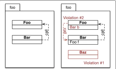
In object-oriented systems, the relations among compo-nents are accessing attributes, calling methods, inheriting types, and instantiating objects. Figure 1 shows two types of violations occurring in a hypothetical scenario. On the left side, we can see the planned architectural model. On the right side, we see a source code projection of such system.Violation #1is a structural violation because com-ponent Baz did not exist in the planned architecture’s hierarchical structure.Violation #2is a relational violation because, in the planned architecture,Fooshould not make method calls toBar.
There are architectural conformance verification techniques proposed to tackle the problem of finding divergences between the source code and the planned architecture [10–12]. Dependency constraint language
(DCL) is a declarative language to verify the dependencies among modules in object-oriented systems [12]. DCL was designed to model architecture components as well as the constraints among such components. DCL has the following positive points: (i)expressiveness, DCL supports a wide variety of architectural constraints; (ii)abstraction level, DCL provides a limited support to associate specific source code parts (low level) with abstract elements (high level) by using a module definition; and (iii)applicability, once it is an easy to learn language. Although its many advantages, DCL also has some characteristics that may hinder its adoption in real software development scenarios, as follows:
Fig. 1Structural and relational violations. The planned architecture (left) and the implemented architecture with violations (right)
• Coupling: the DCL architectural specification is stored in a text file placed in the target project structure, which complicates reuse of the specification to other projects.
• Monolithic: the architectural specification is created in a monolithic manner and hence difficult to maintain, especially in larger and modularized systems.
• Non-hierarchical modeling: DCL does not support the creation of hierarchical relations among
architectural elements. Since architectural models are inherently hierarchical, this limits capturing these models with better accuracy.
• Structure constraints: even though DCL has a variety of constraints to control architectural violations, it still lacks some structure constraints to better specify the system’s architecture.
• Limited of conceptual traceability: DCL provides limited support to model relations among conceptual elements from a system and its source code. These conceptual elements are important to provide context for the architecture.
In this context, this paper proposes an extension of DCL, called DCL 2.0, which we implemented the follow-ing features and concepts to fill the gaps from the previous version and to increase reusability:
• Hierarchical modeling: to allow a more faithful capture of the architectural logical models. It also facilitates the architectural visualization in different formats. Moreover, DCL 2.0 architecture models can be composed of any type of artifact found in a software development project, e.g., classes, projects, packages, documentations, etc.
• New constraints and traceability: the new constraints provide more options to tackle structural violations. We also provide traceability among conceptual constraints and source code artifacts.
• Decoupling: the modeled specification is completely decoupled from the target project, which promotes reuse and evolution of the architectural specification.
• Modularization: the specifications are modular which favors reuse among components by using references.
• Tool support: facilitates common activities to specify and to design the architecture, such as editing specifications, and validating and visualizing the architecture.
We detected 771 architectural violations on the analyzed system; 74% of those violations were only detected by the new constraints proposed in DCL 2.0. After the study, our architectural conformance tool was incorporated to the software development process of the company that maintains the evaluated system.
The three main contributions of this paper are sum-marized as follows: (i) the DCL 2.0 language, which was designed for a better usability and reuse than other archi-tectural conformance techniques; (ii) our experimental process used for the evaluation, which monitors architects and developers on tasks related to handling architec-tural violations; (iii) the implemented tool with features to improve the user’s usability and facilitate the adoption of DCL 2.0 in development teams.
This paper is an extended version of our first work on DCL 2.0 [13] where we highlight the following improve-ments: (i) new section comparing architectural confor-mance techniques and their main characteristics; (ii) new section detailing our implemented tool for DCL 2.0; (iii) a more complete and detailed evaluation section; and (iv) a more exhaustive related work.
The remainder of this paper is organized as follows. The “Background” section presents basic concepts to bet-ter understand our proposed solution. The “Proposed language: DCL 2.0” section presents DCL 2.0, the lan-guage’s extension with modular specification, hierarchi-cal relations, and better reusability. The “Tool support: DCL2Check” section shows DCL2Check, a tool that implements our proposed solution. In the “ Evaluation” section, we evaluated the use of DCL 2.0 in a large sys-tem developed for the Minas Gerais government state. The “Related work” section presents the related work. Finally, the “Conclusion” section concludes the paper and outlines future work.
Background
In this section, we present all concepts required to fully understand our approach. The “Architectural confor-mance checking” section briefly describes the theory on architectural conformance checking. The “Conformance techniques comparison” section performs a general com-parison on architectural conformance techniques. Finally, the “DCL” section presents DCL, the language we have extended in this paper.
Architectural conformance checking
Software architecture is usually the main artifact designed during software development for reasoning about soft-ware properties either functional or non-functional such as availability or modifiability. Design and architectural decisions have large influence on several implementa-tion artifacts. When developers mistakenly violate these decisions, this leads to the software architecture erosion
phenomenon. This gap between implementation and architecture causes the system to fail to satisfy some of the intended nonfunctional properties [14].
Architectural conformance checking is a process that investigates consistency between different artifacts in a wide scope. The main use is to ensure that the software is implemented according to the planned architecture, which is the foremost high-level artifact. Architectural compliance can be performed in several ways, such as from a high-level model to the source code, and between models at similar abstraction levels. It can also be clas-sified as (i) static and (ii) dynamic. Static means that the source code is statically compared to the software’s archi-tecture view. On the other hand, dynamic means that the source code is analyzed at runtime. Architectural verifica-tion evaluates dependencies between components and are divided into:
• Convergence: when a relation prescribed by the high-level model is followed by the source code.
• Divergence: when a relation not prescribed by the high-level model exists in the source code.
• Absence: when a relation prescribed by the high-level model does not exist in the source code.
After the dependencies have been checked, the next step is to fix the architectural violations found by the verifica-tion process. The correcverifica-tion must be consistent with the system architecture. On the other hand, this correction task is time-consuming, especially when the violations have been accumulated for a long time period. Therefore, the task of correcting architectural violations is important to prevent and to reverse architectural erosion [15].
There are several techniques that aim to support archi-tectural conformance tasks; each one has its positive and negative aspects. In the “Conformance techniques com-parison” section, we conduct a brief comparison of the main techniques.
Conformance techniques comparison
In this section, we present an overview of related archi-tectural conformance techniques to summarize their main characteristics for an easy comparison. Table 1 presents the main techniques according to our study and seven characteristics (modularity,abstraction, depen-dency, structure, reuse, visualization, and easy to learn) each one supports. If the paper describing the technique explicitly stated, the characteristic we marked “Yes.” If the paper does not describe a characteristic but in our analy-sis, we found some alternative feature that could be used in the same context, then we marked “Partial.” Otherwise, we marked “No.”
Table 1Related techniques comparison
Technique Characteristic
Modularity Abstraction Dependency Structure Reuse Visualization Easy to learn
DCL [12] No Partial Yes No No No Yes
Reflection models [11] Partial Yes Yes No No Yes Yes
Vespucci [8] Yes Yes Yes No Partial Partial Partial
DSM [21] No Yes Yes No No Partial Yes
SCQL [23] Partial No Yes Partial No No Partial
Design tests [24] Partial No Yes Partial Partial No Yes
FSML [25] No Yes No Partial Yes Yes No
ArchLint [9] No Yes Yes No No No No
OCL [27] Partial Yes Yes No Partial No No
ADL [28] Partial Yes Yes No No No Partial
important aspect because it allows the specification of independent and flexible models. Abstraction verifies if the technique provides different abstraction levels when specifying architectural components. Lack of abstraction features may over complicate the architectural specifi-cation of systems with a large amount of lower level components. Dependency checks whether the technique provides some way to specify dependencies between com-ponents. Most architectural conformance techniques rely on dependencies definitions because they are intuitive. Structure refers to whether the technique captures struc-tural violations (i.e., inconsistencies related to component creation) or not. We claim (and we further empirically demonstrate) that techniques that capture structural vio-lations are likely to uncover more viovio-lations. Reuse checks if there are features specifically designed to reuse architec-tural specifications for other systems. This decouples the architecture specification and decreases the effort in spec-ifying architectures for other systems. Visualization can be used to assess if the technique provides a tool support to visualize the intended architecture. It can help users to better understand the system architecture. Easy to learn analyzes the learning curve required for understanding the technique and for specifying the intended architec-ture. Techniques that are easier to learn facilitate their adoption.
Dependency constraint language (DCL)
DCL [12] major advantage consists in how easy it is to learn the language and how easy it is to be used for archi-tectural conformance check. DCL relies on simple con-cepts, which requires few keywords combined to create architectural restrictions. The language favors expressive-ness, which allows to model several types of restrictions. There is another important point, DCL is non-intrusive and does not require any source code modification. DCL is a feasible solution to monitor and control dependen-cies on object-oriented systems. However, DCL is not a
complete language for architectural specification. DCL main focus is on dependencies control that may not cap-ture all architectural aspects, such as structural charac-teristics [16]. In DCL, the architectural definitions are monolithic and lack modularity, which can cause prob-lems for the architectural specification [8]. For example, DCL does not support a way to specify components in a hierarchical manner, which is a common occurrence when modeling object-oriented systems [17, 18]. Finally, DCL does not explicitly show architectural convergences, which are an important factor to understand the system architecture [11].
Reflection model
Reflection model [11] is a popular technique for archi-tectural conformance since there are many studies on this particular topic. A strong positive point on adopting reflection models is that their concepts are intuitive and easily adaptable to different scenarios [4, 19, 20]. On the other hand, this technique does not show explicit concern for reusability, and trying to reuse reflection models in different system with similar architectures is not a simple task. Therefore, this lack of reusability can be a barrier to adopt this technique for architectural conformance [19].
Vespucci
Vespucci [8] has many interesting features, such as modular architectural definition and components reuse. Vespucci also allows the modeling of different abstrac-tion levels by usingensemblesandslices. The tool support is a negative point for this technique, which has a sub-par documentation and it appears to be inactive. We also found very few studies to assess the applicability of this technique in real scenarios.
Dependency structure matrix (DSM)
little effort to acquire a general overview of the system architecture, which also shows the dependencies between components [7, 22]. Unlike other techniques, DSM can create a dependency matrix without relying on mapping higher level components. On the other hand, this char-acteristic undermines the reuse to other systems, since there is not a formalization on higher level concepts. DSM also does not support explicit architectural specification, which also hinders reuse.
Source code query languages (SCQL)
There are source code query languages adapted to archi-tectural conformance, for example the SCQL [23]. This technique is very flexible in searching for undesirable code pattern (i.e., architectural violations). SCQL similar-ity to SQL facilitates its adoption, although the features design for object-oriented adds a significant complexity to the language. The language is counter-intuitive to model architectural definitions since every aspect of SCQL is expressed by source code queries. Another problem is that SCQL does not support abstraction for higher level components; it only works at source code level.
Design tests
Design tests [24] employ the concept of unit testing applied to architectural compliance. Since it is based on unit testing, this technique is easy to learn for users who are familiar with testing frameworks. This technique does not facilitate architectural modeling, mainly because it is not intuitive to specify architectural details by using tests. Moreover, design tests do not have features explicitly designed for higher level abstraction.
Framework-specific model language (FSML)
FSML [25] goal is to model architecture focused on frame-works. The technique does not control structural depen-dencies or relations, and uses framework instantiation for architectural conformance. The instantiation feature favors reuse, since it is possible to instantiate architectural models as many times as necessary. On the other hand, the framework-based architectural conformance is not easy to learn.
ArchLint
ArchLint [9, 26] automatically extracts architectural rules from source code version history. Therefore, ArchLint is well suited when the system documentation is not well kept. This is a very strong point that favors the adop-tion of ArchLint. On the other hand, ArchLint requires a higher level architectural model to map the source code into architectural specifications, which may compromise its adoption by inexperienced users. Since ArchLint auto-matically extracts the architectural specification from the source code, it does not (and is not expected to) promote reuse or modularity for its specifications.
Object constraint language (OCL)
OCL [27] is an UML standard that allows the specifica-tion of constraints among objects. This technique has the advantage of being integrated with UML models, and it features object-oriented features such as inheritance, and abstraction. On the other hand, OCL lacks usability which makes it more difficult to learn and adopt. Since it is a standard, OCL does not offer any type of constraint visu-alization. Moreover, OCL reusability depends on whether you can reuse the UML models integrated with it, and as such this might not be a strong suit for this technique.
Architecture description language (ADL)
ADL [28, 29] is a broader term that defines a language that provides means to specify architectural and its con-straints. We can see that OCL, DCL, and others can be considered ADLs, as they fall into its definition. However, for this category, we are analyzing a set of ADLs that were not previously discussed.
Armani [30] is an old ADL with similar characteristics and disadvantages that most ADLs share. More specif-ically, Armani supports different abstraction levels, the specification of dependencies, and limited modular spec-ifications. However, it does not capture structure viola-tions, it does not favor reuse, it has no support to visualize the architecture or the constraints, and it learnability was not a concern when the language was designed.
Alloy [29] defines an ADL that maps the architectural language definition into a model that can be more eas-ily verified for architectural conformance. Unlike other ADLs, alloy does provide a limited support to capture some structural violations.
CLACS [28] uses the concepts of component-based software development to model the architectural speci-fications. CLACS was specifically designed to tackle the lack of reuse faced by most ADLs.
Critical assessment
Most techniques do not explicitly concern with architec-tural reusability. Moreover, few techniques partially sup-port the capture of structural violations while the majority does not support it at all. We can also see little support for modular specifications. Therefore, most architectural conformance techniques lack on these three characteris-tics:reuse,structure, andmodularity. On the other hand, for the positive points, most techniques explicitly specify and monitor dependencies between components. There is also a general concern to provide other abstraction levels when modeling architectures.
DCL
by using a set of architectural rules. Basically, each rule has two elements and one relation between them, as follows:
MAcannot-extend MB
ConstraintMAcannot-extend MBindicates that classes
from moduleMAcannot extend classes from moduleMB.
All DCL constraints follow the same syntax. Indeed, this simple and intuitive syntax is one of the main advan-tages of DCL. Therefore, once the system architect knows the project’s architectural characteristics, it becomes a relatively simple process to employ DCL to model archi-tectural constraints.
We need to follow a few steps to use DCL for architec-tural specification. First, we define the modules, which are the high-level components in DCL. Then, we define the mapping of classes into modules, i.e., in this step, we spec-ify the module that represents source code classes. Finally, we define the constraints between each pair of modules.
Once we have the DCL architectural specification, we can use tools to read such specification and verify the source code for architectural violations. Basically, the specification is created by modules and the constraints between a pair of modules. A module is a set of classes, as shown in Listing 1.
In the example, module Math(line 1) represents only one class (java.lang.Math). In line 2, module Exception
represents two classes: java.lang.RuntimeException and
java.io.IOException. In line 3,JavaUtilmodule that repre-sents all classes from thejava.utilpackage. In line 4, mod-uleJavaSwingrefers to every type defined injavax.swing
package or sub-packages.
DCL classifies its violations into two groups: diver-gencesandabsences. Adivergenceviolation occurs when an existing dependency in the source code violates the architectural model. DCL provides the definition of the following kinds of constraints between modules:
• Only classes from module A can depend on types defined in module B, where the possible
dependencies are as follows:
– only A can-access B: only classes declared in module A can access (calling
methods, reading or writing to fields) non-private members of classes declared in module B.
– only A can-declare B: only classes
declared in module A can declare variables of types declared in module B.
– only A can-handle B: only classes declared in module A can access and declare variables of types declared in module B. This is an abbreviation foronly A can-access,
can-declare B.
– only A can-create B: only classes declared in module A can create objects of classes declared in module B.
– only A can-extend B: only classes declared in module A can extend classes declared in module B.
– only A can-implement B: only classes declared in module A can implement interfaces declared in module B.
– only A can-derive B: only classes declared in module A can extend a class or implement an interface declared in module B. In other words, this is an abbreviation for
only A can-extend,
can-implement B.
– only A can-throw B: only methods from
classes declared in module A can return with exceptions declared in module B raised.
– only A can-useannotation B: only
classes declared in module A can use annotations declared in module B.
• Classes declared in module A can depend only on types defined in module B, where the dependencies that can be prescribed are similar to those described for theonly-can constraint (declare, handle, create, extend, implement, derive, throw, and
useannotation). For example,A
can-access-only Bdefines that classes declared in module A can access only non-private members of classes declared in module B.
• Classes declared in module A cannot depend on types defined in module B. The dependencies that can be forbidden are similar to those described theonly-can constraint. For example,A cannot-create B
defines that no classes declared in module A can create objects of classes declared in module B.
On the other hand, an absenceviolation occurs when the source code does not follow a dependency that is pre-scribed by the architectural model. In order to capture absences, DCL supports the definition of the following constraints:
can be prescribed are similar to those described for divergence violations. For example,A
must-derive Bdefines that all classes declared in module A must extend a class or implement an interface declared in module B.
Figure 2 summarizes the language syntax.
DCLsuite is a plug-in to the Eclipse Integrated Develop-ment EnvironDevelop-ment (IDE). It impleDevelop-ments DCL to perform architectural conformance verification. DCLsuite has an editor to create and edit specifications, which are stored in a file with the .dcl extension. The .dcl file must be placed in the root directory of the target project. In fact, DCLsuite reads this file to analyze the source code search-ing for architectural violations, i.e., it automatically checks the source code. The violations found by DCLsuite are presented as errors in the EclipseProblemstab interface.
DCL also has an extension, called DCLfix, that pro-vides recommendations for developers to solve problems related to architectural erosion [15, 31]. Moreover, DCLfix suggests refactoring recommendations to the violations that were detected during the architectural verification done by DCL. Another DCL-based tool, called ArchRuby, was proposed to verify the architectural conformance of dynamically typed languages [32].
In the remainder of this paper, we refer to the original DCL language as DCL 1.0 to avoid being mistaken with our proposed extension.
Proposed language: DCL 2.0
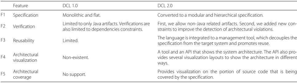
In this paper, we propose DCL 2.0, an extension on DCL 1.0 by introducing modular, reusable, and hierarchical specification models. The objective is to improve the orig-inal DCL language with the detection of new types of architectural violations. We also improved several other language aspects such as the architectural specification, documentation, and visualization. Moreover, our motiva-tion to propose an evolumotiva-tion for DCL 1.0 is to enhance it with important features to be more effective in real software development scenarios. Table 2 highlights the main features reworked by our proposed language—DCL 2.0—and their situation in the original DCL 1.0.
Fig. 2DCL constraints (adapted from [12])
Hierarchical and modular specification
Software development usually uses artifacts composed of components from a higher abstraction level to rep-resent the system’s architecture. This situation is more common in the beginning stages of the development, where the architectural requirements are still unclear. As the development progresses, the architecture is further detailed and its higher level components are decomposed into smaller ones (e.g., sub-modules, packages, directo-ries, classes, and files). We can observe a hierarchical pattern when we detail such smaller components. Archi-tectural models reflect the system’s internal structure and they can be used to communicate the software architec-ture [7, 8]. A few other approaches provide hierarchical specification arguing that a hierarchical model is easier to work considering components from different abstraction levels [7, 8].
Our proposed language, DCL 2.0, supports hierarchi-cal and modular specification. By contrast, DCL 1.0 only supports a monolithic and flat specification where each module or component is defined independently from each other.
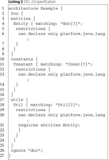
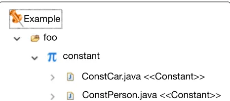
Figure 3 represents the logical (a) and physical (b) struc-ture for a hypothetical system. Listing 2 shows the spec-ification using DCL 2.0 for the same fictitious system. We can see the following three models have a hierarchi-cal nature: (i) the logihierarchi-cal model (Fig. 3a), (ii) the physihierarchi-cal model (Fig. 3b), and the DCL 2.0 specification (Listing 2). On the other hand, DCL 1.0 would define every compo-nent isolated from each other, and without any indication that a component could include or be a part of other components.
In Listing 2, we defined the component foo (line 2) for the example architecture. DCL 2.0 allows hierarchical specification of modules; in this case,foocontains other three components:entities(line 3),constants(line 10), and
utils(line 17). Each component can map and group lower level artifacts (source code and other files) into a higher abstraction definition. For instance, inside the component
entities, we map file names that begin with “Ent” to the newly definedEntityabstraction (line 4), and all architec-tural constraints this component follows (lines 5 to 7). We can also see that Fig. 3 shows an example of this represen-tation whereEntCar.javaandEntPerson.javaare classified asentities.
A software modularity is defined as a way to imple-ment more flexible and comprehensible systems, which impacts directly on its maintenance tasks [33]. In software architecture, modularity is also very important. We can observe this importance in the architectural model 4+1, where views like logical view and implementation view
Table 2DCL 1.0 and DCL 2.0 comparison
Feature DCL 1.0 DCL 2.0
F1 Specification Monolithic and flat. Converted to a modular and hierarchical specification.
F2 Verification Limited to only Java artifacts. Verifications arealso limited to dependencies constraints. First, we allow non-Java related artifacts. Second, we added new con-straints to improve the detection of architectural violations.
F3 Reusability Limited. The language is integrated to a management tool, which decouples the specification from the target system and promotes reuse.
F4 Architectural
visualization Non-existent.
A tool and an API that shows the system architecture. The API also pro-vides several visualization layouts to show the architecture in different ways.
F5 Architectural
coverage No support.
Provides visualization on the portion of source code that is being covered by the specification.
we explain in related work (the “Related work” section), most architectural specifications are monolithic in nature. DCL 2.0 implements a modular specification by using a cross-reference mechanism, where an element defined in a specification file can be referenced by another file. As already illustrated in Listing 2, we can see component
plataform.java.lang(lines 6, 13, and 20) were not defined in the current file, they are references. One of the main advantages for this modularity specification in DCL 2.0 is the reuse of architectural components, i.e., frameworks, APIs, and libraries can have its components specified only once and reused by other projects.
DCL 2.0 also requires a more formal specification than other languages. For example, we can observe the ignore keyword, which informs that componentdoc
should not be considered as an architectural artifact (Listing 2, line 26). More specifically, ignored artifacts are not verified or visualized by the tools using DCL 2.0
specification. Particularly for Listing 2, if theignore key-word did not specify thedoccomponent, a violation would be generated.
Non-java artifacts
One of the new improvements of DCL 2.0 over DCL 1.0 is the possibility to work with non-java related artifacts. This is important because a software project may contain different artifacts, such as documentations, style sheets, web pages, and configuration files.
For example, Listing 3 shows theviewcomponent spec-ification using DCL 2.0. First, we define theview compo-nent (line 1), which is composed by a directory or folder with the name “view” (line 2). Inside the view compo-nent we create a module that contain any folder (lines 3 and 4). We can see that thepagecomponent (lines 5–7) is composed by artifacts with xml, zul, or html extensions (line 6).
New violation types
The hierarchical features introduced in DCL 2.0 provided a way to verify new types of architectural violations. We classified these new types asstructural violations, which occurs when a code element diverges from the hierarchi-cal component specification. We detail the new structural violations types as follows.
Unknown component
This violation occurs when the language finds a source code artifact that does not fit into the components defined
in the architectural specification, and consequently, such artifact is considered unspecified (or undefined) in DCL 2.0. Figure 4 shows an example ofunknown component
violation. In the example, we have two violations related to the existence ofFooHelper class and thebar package (Fig. 4b), which there are no corresponding components in the architectural model (Fig. 4a).
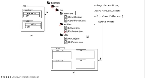
Unknown reference
This violation occurs when an instance of a declared component references an unknown component. In other words, an unknown reference reveals when an unspec-ified element (either internal or external) is referenced by a source code artifact. Figure 5 shows an example of unknown reference violation, whichEntPersonclass refer-encesjava.rmi.Remoteclass that was not specified in any component.
Incorrect location
This violation occurs when the language identifies a valid instance of a code artifact that belongs to an archi-tectural component, although the archiarchi-tectural location diverges from where the artifact was supposed to be implemented. Figure 6 presents an example showing an incorrect location violation. In the figure, entity class Ent-Person is located in the utilscomponent, but that class should be placed in theentitiescomponent (dashed line arrow).
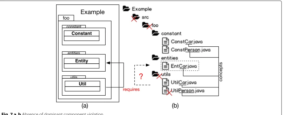
Absence of dominant component
DCL 1.0 does not support the specification of dependen-cies among components related to the same concept. To address this issue, DCL 2.0 proposes a new type of con-straint represented byrequireskeyword. The purpose for this new constraint is to provide traceability between the conceptual model and source code elements. For example, line 21 in Listing 2 establishes that every instance from the
Utilcomponent must be related to anEntitycomponent related to the same concept.
An absence of dominant component violation occurs when it is not possible to find the dominant component. Figure 7 shows an example of such violation. In Fig. 7a, we can observe the conceptual relation among the com-ponents. By our specification, to create classUtilPerson, it should also exist aEntPersonclass (Fig. 4b). The under-lined class names in the figure show essential concepts for the system. Based on the naming convention, DCL 2.0 identifies the code artifacts related to the same concept (matchingkeyword).
Architectural reusability
Fig. 4 a, bUnknown component violation
In DCL 2.0, the specification is decoupled from target system. This difference makes the DCL 2.0 possible to reuse any architectural specifications in DCL 2.0. More-over, this new feature is better to handle the architectural evolution because it allows the specifications to be man-aged and distributed by software configuration tools in a similar way as it is done with source code.
Architectural coverage
Another important new feature of DCL 2.0 is a simple metric to indicate how much of source code was analyzed. Due to the hierarchical specification, all source elements must be verified by the language, except for the elements declared with theignore keyword. In general terms, the less elements are ignored, the greater is the architectural
Fig. 6 a,bIncorrect location violation
coverage. For example, if we consider a system with 100 artifacts (classes, XML, JavaScript, documentation, etc.) with only 70 of those are considered architectural compo-nents, then for this case the architectural coverage is 70%. By default, binary files are excluded for the architectural coverage calculation.
Architectural visualization
Understanding the architectural specification of a sys-tem is important to avoid the proliferation of violations [11]. Therefore, visualizing the planned architecture can aid system architects to better understand it, which can contribute indirectly to the system architectural con-formance. DCL 2.0 hierarchical model allows for three different types of architectural visualizations: (i) textual
shape, (ii) component tree, and (iii) code artifacts and their respective architectural component. A fragment of the third visualization can be see in Fig. 8.
Another noteworthy point is that the visualizations reflect the modeled architecture, which is not just a stan-dard package overview as provided by most IDEs. For example, suppose an architecture component in DCL 2.0 calledwebpagesthat is composed of every html file. How-ever, html files for this system are spread across multiple folders or packages. Moreover, while our tool would show every html artifact as belonging the webpages architec-ture component, an IDE package view would not. As such, the user in an IDE would be required to search for those artifacts following the package structure which does not reflect the architecture component.
Fig. 8Architecture and code visualization
Tool support: DCL2Check
We developed a tool, called DCL2Check (available at github.com/aserg-ufmg/dcl2check), that uses DCL 2.0 to verify the applicability of our proposed solution and to aid our evaluation. The tool is implemented as a plug-in for Eclipse IDE. It provides essential functionalities, such as architectural conformance verification and high-level architectural visualization.
The “Overview” section presents an overview of the tool and its main components. The “Architecture” section describes the tool’s architecture. Last, the “Features” section highlights DCL 2.0’s main features.
Overview
We used the Eclipse platform and Xtext as the main components to implement our tool. Eclipseis a popular open-source IDE (Integrated Development Environment).
Xtext is a framework for development of program-ming languages and domain-specific languages. With
Xtextyou define your language using a formal grammar specification. As a result, Xtext provides the elements required for domain specific language processing, includ-ing parser, linker, type checker, and compiler as well as editing support for Eclipse, IntelliJ IDEA, and for any web browser.
DCL2Checkis publicly available as a plug-in forEclipse. We created a specific DCL 2.0 project in the Eclipse plat-form to use the tool. This project is needed to store the architectural specification using the DCL 2.0 language. Once created, the specification project should be exported in JAR (Java ARchive) format. The system we want to perform architectural conformance adds the DCL 2.0 specification JAR file to its project dependencies. The tool identifies the architectural specification among the project system dependencies and employs it to perform the architectural compliance task. It is important to high-light, that even though the specification is exported as a
JARfile, it can be used for software projects written in any programming language and not just Java. Since our tool is integrated with Eclipse, it can work with any language supported by the Eclipse platform.
We also integrated the tool with theMavenframework to support the distribution of architectural specifications in remote repositories. Another feature introduced by
Mavenis that it can access the remote repositories to auto-matically update the architectural specification for each developer machine. As we can see it is easy to reuse spec-ifications to other systems, since they are decoupled from the software project.
Architecture
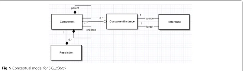
Figure 9 presents DCL2Check conceptual model show-ing its main entities (Component, ComponentInstance,
Reference,Restriction).
• Component:it is the main model entity for DCL 2.0.
We useComponent to represent conceptual elements from the system. This entity possesses two self-relations (parent and children), to allow a hierarchical specification and navigation through the architectural components.
• ComponentInstance:entity that represents source
code portion related to a specific component.
• Reference:entity that represents a relation between
two component instances (i.e., model a dependency between a source component instance and a target one).
• Restriction:entity that represents rules, restrictions,
or constraints applied to a specific component.
Features
In this section, we present the following main fea-tures implemented by our tool: specification editor (the “Specification editor” section), architectural verifica-tion (the “Architectural verificaverifica-tion” secverifica-tion), and visual-ization (the “Visualvisual-ization” section).
Specification editor
The tool has built in editor specifically designed to handle architectural specifications in DCL 2.0. The editor offers syntax highlight, cross-reference, and autocomplete to aid in the writing of specifications. Moreover, the editor also validates the specification automatically, showing syntax errors just in time. These functionalities attached to the editor are important to improve the usability and ease the learning curve to new users.
Architectural verification
For the architectural conformance task, our tool offers explicitly designed features to handle it. The user can enable the architectural verification for each Eclipse project in theconfigurationmenu. Once enabled, the ver-ification task can be executed in the following ways: (i)
Fig. 9Conceptual model forDCL2Check
artifact is modified; (ii) build feedback, which the veri-fication is processed when the project is compiled; and (iii)off-line feedback, which the architectural verification is only performed by demand, i.e., only when the user explicitly invokes the tool command (in the Eclipse IDE) to perform the architectural compliance check.
Figure 10 shows a violation in theEntPersonclass. The tool marks the source code line on the artifact that caused the violation. A textual message is also showed to explain the violation found by our tool. The message is to facili-tate the users’ understanding. We think it is noteworthy to point out that these messages can be customized and defined using DCL 2.0.
Visualization
As we showed in the architectural conformance tech-niques comparison (the “Architectural conformance checking” section), not every technique provides a visu-alization feature. We claim visuvisu-alization is important to aid the development team in better understanding the designed architecture. Therefore, we implement in our tool three types of visualizations: (i) textual shape, (ii) component tree, and (iii) code artifacts and their respec-tive architectural component.
The visualization types provided by DCL2Check are independent from the architecture specification, which allows new tools or extensions to provide more visualiza-tion opvisualiza-tions for DCL 2.0 in the future. Moreover, our tool
Fig. 10Architectural violation
visualizations reflect the modeled architecture that is dif-ferent than the common package overview provided by IDEs.
The tool also uses Eclipse’sView ConsoleandProblems
to show details on the architectural violations. We also show theArchitectural Coverage for each project under the project’s properties.
Evaluation
In this section, we report a case study where we applied an architectural conformance check using DCL 2.0 to a large system. The system is maintained by PRODEMGE, which is a government information technology company from the state of Minas Gerais, Brazil.
Research questions
The main objectives behind our research ques-tions is to understand the architectural erosion phenomenon (RQ#1) and to evaluate the DCL 2.0 lan-guage (RQ#2).
Research questions related to architectural erosion:
RQ# 1.1:Why do architectural violations occur?
RQ# 1.2:How does the development team handle
the violations?
Research questions related to DCL 2.0:
RQ# 2.1:Can DCL 2.0 be used to avoid architectural
violations?
RQ# 2.2:Do the new concepts and features
introduced by DCL 2.0 improve the architectural verification process?
RQ# 2.3:CanDCL2Check tool be used in real
software development process to perform architectural verification?
Methodology
section). Finally, we show a detailed conformance archi-tecture process for the case study (the “Process definition” section).
System selection
There are studies arguing the necessity to evaluate new researches in real systems [20, 34]. Therefore, we chose to verify the applicability of DCL 2.0 by using a real system and their development team. We defined the following criteria to select a PRODEMGE system that was more appropriate to our context of architectural conformance:
• The system needs to be of medium or large size because larger systems are more inclined to have architectural violations [35].
• The system’s source code language should be Java. Although DCL concepts and its architectural conformance can be applied to any object-oriented system, the original DCL 1.0 has already a Java implementation.
• The system should be under development, since it is less likely for stable and mature systems to present violations.
• The development team should be medium sized. Small teams are less likely to deviate from the planned architecture; usually, the same team who defines the architecture is also the one who implements the system.
• The development team should be heterogeneous. The main reason is to avoid a biased team composed mostly of very experienced developers or
inexperienced ones.
Therefore, we selected theSSC-ADMIN system, which is an administration module for theSSCsystem. TheSSC
system is used by government agencies to manage digital identities from the Minas Gerais state. The target sys-tem is coded in Java and its main functionalities include the general management of unities (government branches, commissions, etc.), systems, users, profiles, resources, and auditing.
Metrics
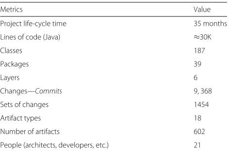
Table 3 summarizes theSSC-ADMINsystem metrics that we uncovered during our analysis.
We would like to clarify some of the summarized met-rics presented in Table 3. First, the project life-cycle time accounts for the conceptual of the system, the approval of the project by the company, the development time, and maintenance (for correction and enhancement). We also would like to note that since this project was developed in a government branch, there is some bureaucracy that affects the project time. The first release of the system was around 6 months after the beginning of the project. The lines of code, classes, and packages only account
Table 3SSC-ADMIN metrics
Metrics Value
Project life-cycle time 35 months
Lines of code (Java) ≈30K
Classes 187
Packages 39
Layers 6
Changes—Commits 9, 368
Sets of changes 1454
Artifact types 18
Number of artifacts 602
People (architects, developers, etc.) 21
for Java artifacts because we used an automated tool to acquire such information. However, there are many non-java artifacts that were not accounted for (e.g., web pages, documentations, xml, etc.). The people involved with the project account for developers, architects, interns, and any person who had some contact with the system. It is noteworthy that not all of them worked at the project at the same time, but during the course of the case study (35 months). In fact, new developers arriving to replace more experienced ones was one the reasons that con-tributed for the inclusion of architectural violations.
Process definition
Our evaluation process was inspired by other researches on architectural violations [4, 36]. We adapted the pro-cess to make it more iterative and incremental, as shown in Fig. 11. Our defined process for the case study included the following steps:
1. Development team preparation. 2. Source code preparation. 3. Architecture formalization.
4. Architectural verification and violation analysis. 5. Violations removal.
6. Generate a new system’s version. 7. Monitoring and evolution.
1. Development team preparation: In this step, we explained the DCL 2.0 language to the team. We also sepa-rated the development team into two groups. Group 1 was composed of architects who are responsible to specify the system architecture in DCL 2.0. Group 1 is also responsi-ble to refactor the code to remove architectural violations. Group 2 is composed of developers that keep the standard software development process followed by the company.
Fig. 11Defined process for the case study
3. Architecture formalization: Group 1 (architects) spec-ifies the system’s architecture using DCL 2.0 language and our tool (DCL2Check), which should map architectural components into code elements. The architects specified the system based on the common stereotypes employed by their company to map the components. For instance, a
PersonCtrclass (as well as any class with the “Ctr” suffix in their name) should be mapped to theControlcomponent.
4. Architectural verification and violation analysis: After the architecture formalization (step 3) , the architects (group 1) execute DCL2Check to compare the planned architecture to the implemented code and to reveal the architectural violations.
Since the architects are working on a large system, there is a strategy to handle violations. The strategy is to ver-ify each module in sequence—starting with the module with the smaller number of dependencies—, to analyze the violations, and to schedule for the code or architectural changes.
5. Violations removal: The violations found on the last step are removed. More specifically, each violation is fixed, documented, and committed to the repository. The violation can be removed by modifying artifacts to fit into planned the planned architecture, or the archi-tectural specification can be adapted. Group 1 repeats steps 2, 3, 4, and 5 for each module until all system’s viola-tions are fixed.
6. Generate a new system’s version: After all violations are removed from the secondary branch, the changes are pushed to the main branch to create a new version of the system. After joining the two branches,DCL2Checkis installed on group 2 machines to inhibit further violations.
7. Monitoring and evolution: After group 1 creates a new system’s version, the resulting architecture is presented to the entire development team. We also analyze the result-ing architecture for the case study. After that, the archi-tects keep track of the system’s architecture for adaptation, evolution, and correction. The architects should also aid the developers to understand the planned architecture and the violation warnings provided byDCL2Check.
Case study execution
Team preparation
We explained DCL 2.0 to the development team and divided them into two groups: group 1 with two architects and group 2 with eight developers.
Source code preparation
The development company, PRODEMGE, employs two major tools: (i) IBM-RTC (jazz.net/products/rational-team-concert) (Rational Team Concert) and (ii) Maven
(maven.apache.org). The first tool is used for version con-trol and the second tool for dependencies management. The tools were used to manage source code artifacts (e.g., java, js, and xml files) as well as architectural specification (e.g., asml files).
Architectural formalization
SSC-ADMIN system is divided into layers, where each layer is an independent module responsible for a spe-cific architectural functionality. The DCL 2.0 spespe-cifica- specifica-tion followed the same decomposispecifica-tion into layers, i.e., the architects created DCL specification for each layer of the SSC-ADMIN system. The system layers are the fol-lowing:common,domain,interfaces,infrastructure, busi-ness, andweb. Each of those layers is associated with an Eclipse project. Figure 12 shows the layers and the Eclipse projects.
According to our methodology, thecommonlayer was the first to be formally specified because it has the smallest number of dependencies. On the other hand,webwas the last to be specified because it has the largest number of dependencies.
Fig. 12 a,bComponent layers forSSC-ADMINsystem
classes were mapped according to their layer. There were JavaScript and XML files that also needed to be mapped into architectural components by the architects.
Listing 4 shows the final architectural specification defined in DCL 2.0 for the domainlayer. We made the architectural specifications for the remaining layers pub-lic available (https://github.com/aserg-ufmg/sbcars2016). We can observe the mapping of classes into components by using the matching keyword. In lines 7 and 8, the mapping defines theEntityandAudityEntitycomponents, respectively. More specifically, the declarations state that any artifact whose name ends withVObelongs to com-ponent Entity, and any artifact whose name ends with
AudVObelong to theAuditEntitycomponent. For exam-ple, class UserVObelongs to theEntitycomponent, and theAuditoryAudVOclass belongs to theAuditEntity com-ponent. It is important to highlight that DCL 2.0 tool always matches artifacts to the most related component according to its specification pattern. For instance, even thoughAuditoryAudVOcould match the pattern defined for Entity, it has a much higher correlation to the pat-tern defined forAuditEntityand hence it is assigned to the
AuditEntitycomponent.
Almost every component from the target system were mapped by usingnaming standards. However, there were a few cases were we mapped components by their file
Table 4Coverage by architectural layer
Coverage
Project (layer) Components no. Artifacts % Lines %
Web 25 82 97
Business 21 63 94
Infrastructure 11 50 77
Interfaces 14 53 77
Domain 10 67 93
Common 7 33 47
Total 88
extension. Table 4 reports the number of components and the coverage percentage for each layer. We can see that the coverage may vary greatly for each module. The main reason for the coverage to be lower in smaller projects (e.g., common and infrastructure) is because the archi-tects decided to ignore configuration files related to IDE and integration plugins (e.g., Maven, JBoss, and RTC). Therefore, for smaller projects, the ignored files have a bigger impact on its coverage.
Architectural verification and violation analysis
In this step, the architects define the constraints modeling the relations between modules. Table 5 reports the layers, number of constraints, and the number of references specified in DCL 2.0. For example, Listing 5 presents the
Entity component (previously mentioned in Listing 4)
after the architects defined constraints indicating that entities should be serializable (line 4) and must extend
Table 5Constraints and references
Internal components
Project (layer) Constraints no. References no.
Web 8 42
Business 11 72
Infrastructure 11 31
Interfaces 8 20
Domain 8 22
Common 2 6
Total 45 193
amount of repeated references to external components (147 to be exact) during the definition of architectural rules. For this reason, we advised the architects to specify components related to frameworks, APIs and Java stan-dard libraries into a specific project to promote reuse and decouple these external components.
In the previous step (architectural formalization), the hierarchical restrictions were already defined because the architectural specification implicitly imposes restrictions to insert components to the structure. Therefore, code artifacts that do not fit into a hierarchical model represent violations.
At first, we observed a high number of structural violations (91%) when compared to number of relation violations (9%). The architect analysis detected two defi-ciencies: (i) code elements that did not have correspond-ing architectural components, e.g., FunctionalTypeTest
class was considered to be part of an unknown compo-nent; and (ii) code elements that do not fit to the naming standards, e.g., classMailServicehad the characteristics of a persistence class and hence it was renamed to Notifica-tionDAO. More specifically, in the PRODEMGE company all helper and testing classes are considered to be a part of system architecture and hence these classes should be modeled into relevant architecture components.
Violations removal
The system showed a high number of violations of two types: unknown component and unknown reference. For
this reason, the architects followed two major actions: (i) alter and adapt the architectural specification in DCL 2.0; and (ii) adjust the source artifacts by refactoring the arti-facts that do not fit the architectural components.
After that, the architects started to remove the remain-ing violations until 80% were fixed. A portion of the violations could not be removed because they were con-sidered high risk. Therefore, the architects used the filter feature from DCL 2.0 to avoid these violations to be reported to the development team. However, these high-risk violations were documented and presented to the project managers. The project managers assured they will make plans to carefully remove these violations in the near future. Most of these violations werestructural violationsoccurring in non-java artifacts, which corrob-orates our hypothesis that it is not sufficient to apply architectural conformance only to the main source code language.
Generate a new system’s version
After the architects removed the violations, they were required to join the source code branches. The mod-ules went through another architectural conformance check to capture new possible violations. In total, 11 new violations were detected and removed. After the refactoring, we created a new version for the archi-tectural specification and the source code. Then, we installed DCL2Check in group 2 (developers) machines to assure the architectural conformance from this point forward.
Monitoring and evolution
In the first weeks, the architects identified code violations that should not be occurring sinceDCL2Check tool was installed in the developers’ computers. The architects ver-ified the problem and realized that the developers were disabling the validation tool in Eclipse IDE for perfor-mance issues. On average, the tool required between one and eight seconds (usually, one second for small modules and eight for bigger ones).
To avoid this issue, we adapted the DCL2Check with the possibility to perform a architectural verification on demand or when the project is built (i.e., a com-plete project compilation) besides the incremental just-in-time verification. We already described those verification options in section 2, respectively asoff-line feedbackand
Results
The results presented in this section are extracted from the development history of the target system, between June 2013 and April 2016 (35 months). The architectural specifications and violations removal process began in July 2, 2015 and lasted until August 27, 2015 (58 days). During this period, DCL 2.0 was employed to reveal vio-lations that may have occurred since the initial system development. After the violations removal, the DCL 2.0 verification tool was installed on the development team computers. We followed this step from September 2015 to April 2016 (8 months).
As we previously discussed, there was a high number of architectural violations of two types: unknown com-ponent and unknown reference. Figure 13 reports the violations found by our tool and classified them into three categories: (1) unknown component and unknown ref-erence violations; (2) other DCL 2.0 violations; and (3) DCL 1.0 violations. We can observe that other types of violations increases when we remove violations from cate-gory 1 (i.e., unknown component and unknown reference violations). This observation reinforces our hypothesis that unknown component and unknown reference viola-tions may, in fact, mask other types of violaviola-tions.
Figure 14 reports the number of commits that pre-sented (or not) architectural violations. In this figure, we highlight two dates: (i) July 2015 marks the beginning of DCL 2.0 specification, and (ii)September 2015marks when DCL 2.0 verification started. There is no direct rela-tion between the number of commits and the number of violations. For instance, Fig. 14 shows periods with high number of commits and few violations, and vice versa.
We observed a trending pattern of new violations dur-ing the development. More specifically, the first 2 months showed in Fig. 14, 2013/06 (June) and 2013/07 (July), show a great number of violations because during this time period most classes were added to the project.
Cat.1 (DCL 2.0)
Cat.2 (DCL 2.0)
Cat.3 (DCL 1.0)
Violations
0
100
200
300
400
350
67
207 227
57 194 Before After
Fig. 13Violations found before and after the removal step
During January 2015 to April 2015, two main fac-tors related to evolution maintenance contributed to the increase in violations: (i) the system was enhanced with new features related to functional requirements; and (ii) new code added for a JSON framework exten-sion. Figure 15 shows the number of features added to the system. We can observe a positive relation between adding new features and introducing architectural viola-tions. We run Spearman’s rho test to measure the strength of this association (from July 2013 to June 2015), which was considered strong (rho = 0.694). The violations were accumulated until DCL 2.0 was incorporated to the development process, after that, violations were removed constantly. In summary, adding new features creates more violations than periods where corrective maintenance were applied to existing features. We can also observe the importance of an architectural conformance in the devel-opment process because after August 2015 the number of violations greatly decreases.
Figure 16 shows changes and violations on the source related to developers’ profile. We can see that all pro-files introduce architectural violations. Moreover, if we observe violations related to complex code changes,senior
developers introduced approximately ten times more vio-lations than other profiles. The reason for this occurrence is becauseseniordevelopers are delegated to more com-plex coding tasks, which have a higher probability to impact on the architecture.
Figure 17 shows the amount of development tasks each profile accomplished. We can see that senior develop-ers are responsible for more tasks than other profiles. If we compare both Figs. 16 and 17, we can notice the more tasks a developer implements on the system, more architectural violations are also introduced.
Discussion
In this section, we answer our research questions defined in the beginning of this case study.
RQ#1.1) Why do architectural violations occur? When we analyze the results, we can see that architectural violations can occur in the earlier stages of software development. Moreover, the architectural degra-dation does not fit into a linear pattern. The results show a clear relation between violations and adding new features to the system, i.e., code changes that adds new functional-ities are more likely to spawn architectural violations than those changes that only maintain an already implemented functionality.
# of Commits
0
200
400
600
800
1000
13−06 13−07 13−08 13−09 13−10 13−11 13−12 14−01 14−02 14−03 14−04 14−05 14−06 14−07 14−08 14−09 14−10 14−11 14−12 15−01 15−02 15−03 15−04 15−05 15−06 15−0715−07 15−08 15−0915−09 15−10 15−11 15−12 16−01 16−02 16−03 16−04
39
106
24 8
14
4
10 18
10
26 7
5
6 2
11 20
7 10 81 75
26 36 7
10 2
5 37
3
9 4
789 606
443 479 710 304 279 284 202 168 92 108 173 84 66 165 224 188 171 204 207
154 168 193 224 955 474487284 167 47 47 145 162 133
Commits with Violations Commits without Violations
Fig. 14Commits and violations
from the development team and according to them the main causes of introducing architectural violations are the following: (i) lack of knowledge and understanding of the architectural conventions adopt for the system, mostly because the extensive documentation; and (ii) lack of architectural evolution, because developers when faced with a limitation imposed by the planned architecture would built their own solution without asking the archi-tect and adapting the archiarchi-tecture.
The developers also associated stressing over project’s deadlines as a secondary factor to architectural diver-gence. Developers stated that they do not contradict architectural conventions on purpose. However, the developers also stated that the pressure and stress related to fulfill work deadlines may have inhibited them to seek more information about the architecture when needed.
0
100
200
300
400
500
600
# of f
eatures/violations
13−06 13−07 13−08 13−09 13−10 13−11 13−12 14−01 14−02 14−03 14−04 14−05 14−06 14−07 14−08 14−09 14−10 14−11 14−12 15−01 15−02 15−03 15−04 15−05 15−06 15−07 15−08 15−09 15−10 15−11 15−12 16−01 16−02 16−03 16−0415−07 Beginning of DCL 2.0 Features
Violations
Fig. 15New features and violations
RQ#1.2) How does the development team handle the violations?
When we analyzed the history of changes for the system, we can see that violations were removed even before the installation of our tool. Therefore, the development team fixed violations without a proper process or planning. However, most of the violations removed before DCL 2.0 had low complexity, which leaves higher complexity vio-lations present in the system. The developers stated the main factor to not remove more complex violations is the risk to introduce bugs into the system.
The developers also stated that not having tool support to find architectural violations since the beginning of the development as a difficulty factor to not removing them,
Senior Developer
Full Developer
Junior Developer
# of Violations per Comple
xity
0
5
0
1
00
150
200
250
300
66 74
140 280
6 48
111 165
4 40
88 132 High Medium Low Total
![Fig. 2 DCL constraints (adapted from [12])](https://thumb-us.123doks.com/thumbv2/123dok_us/857177.1583308/7.595.58.292.616.719/fig-dcl-constraints-adapted-from.webp)