IPSJ Transactions on Computer
Vision and Applications
Kagaet al. IPSJ Transactions on Computer Vision and Applications (2019) 11:8
https://doi.org/10.1186/s41074-019-0060-4
E X P R E S S P A P E R
Open Access
Thermal non-line-of-sight imaging from
specular and diffuse reflections
Masaki Kaga
*, Takahiro Kushida, Tsuyoshi Takatani, Kenichiro Tanaka, Takuya Funatomi and Yasuhiro
Mukaigawa
Abstract
This paper presents a non-line-of-sight technique to estimate the position and temperature of an occluded object from a camera via reflection on a wall. Because objects with heat emit far infrared light with respect to their
temperature, positions and temperatures are estimated from reflections on a wall. A key idea is that light paths from a hidden object to the camera depend on the position of the hidden object. The position of the object is recovered from the angular distribution of specular and diffuse reflection component, and the temperature of the heat source is recovered from the estimated position and the intensity of reflection. The effectiveness of our method is evaluated by conducting real-world experiments, showing that the position and the temperature of the hidden object can be recovered from the reflection destination of the wall by using a conventional thermal camera.
Keywords: Non-Line-of-Sight, Thermal Imaging, Far Infrared
1 Introduction
Measuring objects that are hidden from the view of a cam-era is an important problem in many research fields such as robotic vision, autonomous driving, medical imaging, and remote sensing. Non-line-of-sight (NLOS) imaging is a technique to deal with the problem, which reconstructs the position, shape, and reflectance of the hidden objects from indirect light paths. Light emitted from a light source is reflected off objects multiple times in both line-of-sight (LOS) and NLOS scenes and then detected by the cam-era. Although the indirect light paths including reflection from the hidden objects can be a clue to recover images of the NLOS scene, such an inverse problem is a challenging task.
In order to tackle this task, most NLOS imaging tech-niques require a controllable light source. On the other hand, we propose a passive NLOS imaging technique using far infrared (FIR) light. Because all thermal objects radiate FIR light with respect to their temperature, any object in the real world can be regarded as a light source in the FIR wavelengths. We realized this makes the inverse problem simpler. That is, we can formulate it as the one-bounce problem, in which a light ray is assumed to be
*Correspondence:[email protected]
Nara Institute of Science and Technology (NAIST), Ikoma, Nara, Japan
reflected only once, while the active techniques assume a three-bounce problem. In our formulation, the light emit-ted from a hidden object is reflecemit-ted off a wall in the LOS scene and then observed by the camera. We assume that the reflection on the wall can be separated into diffuse and specular components, whose light paths depend on the position of the hidden object, and the intensities relate to the temperature. Thus, separating both the components enables to reconstruct the position and the temperature of the hidden object, as shown in Fig.1. Experimental results show the effectiveness of the proposed method by using a conventional thermal camera.
2 Related work
2.1 Active NLOS imaging
Most NLOS imaging techniques rely on time-resolved imaging using a controllable light source. The early study used a femtosecond-laser to illuminate a scene and a picosecond-resolution streak camera to obtain time-resolved images [1]. Homodyne time-of-flight sensors are also available to obtain time-resolved images [2] and thus to be applied for NLOS imaging [3]. After the avail-ability of single-photon avalanche diode detectors with time-correlated single-photon counting has increased, it is often used for NLOS imaging [4,5].
Kagaet al. IPSJ Transactions on Computer Vision and Applications (2019) 11:8 Page 2 of 6
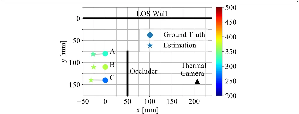
Fig. 1Experimental results of the position and temperature estimation. Although the target objects are located beyond the occluder, the estimated positions are close to the ground truth. Moreover, the estimated temperatures, shown by color, are consistent with the actual temperatures
2.2 Passive NLOS imaging
A few passive NLOS imaging techniques have been pro-posed, recently. Torralba and Freeman [6] showed that an accidental camera can image a NLOS scene. Bouman et al. [7] showed that obstructions with edges, e.g., walls, can be exploited as a camera that reveals the NLOS scene beyond them. Saunders et al. [8] proposed a passive NLOS imaging which requires only a single image captured with an ordinary camera to recover a partially hidden scene and the position of an opaque object in the NLOS scene. Beckus et al. [9] also proposed a passive NLOS imaging by a multi-modal fusion of the intensity and the spatial coherence function.
All the existing NLOS imaging techniques expect from the visible to near infrared light to illuminate the scenes. On the other hand, we utilize FIR light to enable the pas-sive NLOS imaging that recovers not only the position but also the temperature of the hidden object.
3 Thermal NLOS imaging
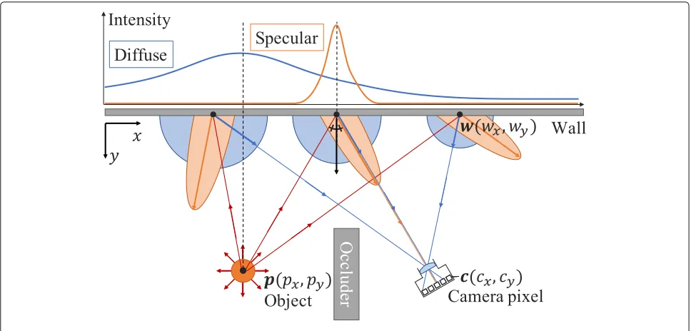
We assume that a target thermal object is located beyond an occluder outside the view of a thermal camera. The camera observes a flat wall in a LOS scene on which the FIR light emitted from the hidden object is reflected. We assume that the reflection of FIR light can be separated into diffuse and specular reflections, as well as the visible light, and the geometry of the wall and the camera is given. Figure2shows the geometry of the scene. To simplify the problem, we assume that the hidden object is sizeless.
The goal of this work is to estimate the position and temperature of the hidden object from a single thermal image. The key idea is that peaks in the intensity distribu-tion on the wall depends on the posidistribu-tion of the object. An observed intensity on the image plane can be projected
onto the wall because of the known geometry. Consider-ing specular and diffuse components separately, a peak in the intensity distribution based on the specular compo-nent is around the position where the incident angle is equal to the outgoing angle, as shown in Fig.2. On the other hand, a peak in the distribution based on the dif-fuse component is around the position where the distance between the object and wall is minimal. Therefore, once both the distributions are separated, we can estimate the position of the hidden object via the backprojection of expected light paths.
3.1 Separation of diffuse and specular reflections
The observed intensity in the image consists of not only the diffuse and specular but also an ambient components. However, the ambient component can easily be removed by subtracting an observation without the hidden object. The separation of diffuse and specular reflections is per-formed on the 1D distribution of intensities on the wall. Because a camera pixelcand a point on the wallware cor-responding to one to one, we can transform the observed intensity into the intensity on the wall via geometric and radiometric corrections. The intensity on the wall can be represented as below:
Iw(wx)=Dw(wx)+Sw(wx), (1)
where Dw and Sw are the diffuse and specular
compo-nents, respectively.
Kagaet al. IPSJ Transactions on Computer Vision and Applications (2019) 11:8 Page 3 of 6
Fig. 2Geometry of the setup and concept
Dw(wx)=adexp
−(wx−μd)2
2σd2
, (2)
Sw(wx)=asexp
−(wx−μs)2
2σ2 s
, (3)
where ad, μd, and σd2 are the scale, the mean, and the
variance of the diffuse component andas,μs, andσs2are
those of the specular component. There is the constraint;
σd> σs, because the spatial spreading of diffuse reflection
is always larger than that of specular reflection. In order to separate both the components, we optimize:
[μd,μs,σd,σs,ad,as]=
argmin
μd,μs,σd,σs,,ad,as
wx
Iw(wx)− ˆIw(wx|μd,μs,σd,σs,ad,as) 2
,
(4)
where Iˆw(wx) is the reconstructed intensity. Figure 3
shows an example of separation.
3.2 Position estimation
The position of the hidden object is estimated using the separated diffuse and specular distributions. Because the outgoing angle of specular reflection is equal to the inci-dent angle, a light path from a point on the wallwto the object point is expected as:
l= w−c
w−c2−2
w−c
w−c2·n
n, (5)
where n is the normal direction of the wall. In general, specular reflection on a real-world material has blurry lobes. Thus, we apply a voting manner to compute the probability distribution of the position. A light path of
specular reflection at each point on the wall is tracked along a directionlin a voting spaceVwhosey-axis is the normal direction of the wallnand the origin ofyis on the wall. Although light paths of diffuse reflection are possi-bly distributed in all directions, the intensity is expected to depend on the distance between the object point and the point on the wall. Thus, a light path of diffuse reflection at each point on the wall is tracked along the normal direc-tion of the wall. We define a voting valuevat a position
(x,y)∈Vas:
v(x,y)=vd(x)+vs(x,y), (6)
where vd and vs are voting intensities derived from the
diffuse and specular components, respectively. The vot-ing intensity from the specular component at the position
(x,y) is based on the corresponding point on the wall, which is determined by wx = cxcyy++cyyx. Thus, both the
voting intensities are defined as:
vd(x,y)=Dw(x), (7)
vs(x,y)=Sw
cxy+cyx
cy+y
. (8)
Normalizing the voting space makes the probability distribution as:
p(x,y)= v(x,y)
x
yv(x,y)
. (9)
Kagaet al. IPSJ Transactions on Computer Vision and Applications (2019) 11:8 Page 4 of 6
Fig. 3Separation result. The observed intensity (green) is separated into diffuse component (blue) and specular component (orange)
3.3 Temperature estimation
The temperature of the hidden object is estimated the the separated diffuse distribution and the estimated posi-tion. FIR light energyEradiated from a thermal object is directly proportional to the fourth power of the object’s thermodynamic temperatureT, according to the Stefan-Boltzmann law:
E=σT4, (10)
whereσ is the Stefan-Boltzmann constant. The radiated light eventually reaches to the LOS wall but is attenuated along the travelling path. The attenuation rate is depen-dent on its distance, which is explained by the inverse-square law. The reached light is diffusely reflected from the wall and then observed by the camera. Thus, the scale adof the diffuse distribution can be expressed as:
ad =
Ekd
ˆ
y2 , (11)
wherekdis the diffuse reflectance of the wall andyˆis the
estimated distance between the object and the wall. Once the reflectance is measured, e.g., by calculating from the estimated scale under the known distance and the tem-perature, the temperature of the hidden object can be estimated as:
T=
adyˆ2
kdσ
1 4
. (12)
4 Experiments
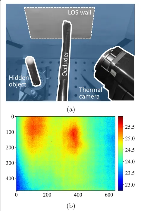
We demonstrate estimations of the position the temper-ature of a hidden object. In the experimental setup, as shown in Fig. 4a, a thermal camera (Nippon Avionics, InfRec R500) observes a flat melamine wall in a LOS scene, on which printing paper is put, and a hidden object is located beyond a black board in a NLOS scene. Two
objects are used as the hidden object: a soldering iron and a hand warmer. The iron can keep different tem-peratures of 270, 320, and 370◦C and the hand warmer warms up to around 50◦C when plugged in. An observed image is shown in Fig.4b in a case of the hand warmer.
Kagaet al. IPSJ Transactions on Computer Vision and Applications (2019) 11:8 Page 5 of 6
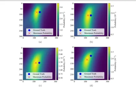
Fig. 5Experimental results of the position estimation.a–cProbability distributions for the position of the soldering iron at the position A, B, and C, respectively.dProbability distribution of the hand warmer at the position A. The blue circle and red cross denote the ground truth and the maximum probability positions, respectively
An aluminum board with grid holes is used for calibrat-ing the camera intrinsic parameters and the geometry between the wall and the camera. The camera and objects are adequately warmed up before starting experiments, and the ambient temperature is kept constant during the experiments.
4.1 Position estimation
First, we evaluate the position estimation of the hidden object. We locate the iron with the temperature of 370◦C at three different positions A, B, and C in the NLOS scene, as shown in Fig.1. An observed image is separated into diffuse and specular components for each horizontal line, and then, the voting is performed to get the probability distribution. The probability distribution for each posi-tion is shown in Fig.5a–c, where the blue circle and red cross denote the ground truth and the maximum proba-bility positions, respectively. The errors in the estimated positions for A, B, and C are 27.41, 26.07, and 31.94 mm, respectively. Second, the hand warmer, whose tempera-ture order is close to human body temperatempera-ture, is located at the position A. The computed probability distribution
is shown in Fig.5d, and the error of the estimated position is 38.08 mm. The results say that the proposed method can reconstruct the position of a hidden object even at a low temperature.
4.2 Temperature estimation
We demonstrate the temperature estimation of the hid-den object. The temperature of the iron is set to 270, 320, and 370◦C for each of the positions A, B, and C. After the positions are estimated, the temperatures are estimated using Eq. (12). The diffuse reflectancekd is ahead
Kagaet al. IPSJ Transactions on Computer Vision and Applications (2019) 11:8 Page 6 of 6
Table 1Experimental results of the temperature estimation
270◦C 320◦C 370◦C
Position A 280◦C (27.77 mm) 335◦C (27.41 mm) 351◦C (24.94 mm)
Position B 283◦C (23.79 mm) N/A (22.98 mm) 365◦C (26.07 mm)
Position C 365◦C (31.94 mm) 441◦C (40.19 mm) 473◦C (36.35 mm)
Because the accuracy depends on the position estimation, the error in the position estimation is shown below the estimated temperature
5 Conclusion
We proposed thermal NLOS imaging to estimate the posi-tion and temperature of a hidden object located beyond an occluder. An observed thermal image is separated into diffuse and specular components. Voting values along all possible light paths for both the components gives us a probability distribution of position. Once the distance between the object and wall is estimated, the temperature of the hidden object can inversely be estimated from the diffuse intensity. Experimental results show that the pro-posed method can estimate the position and temperature of a soldering iron located at the different positions with the different temperatures, and the position of the hand warmer, whose temperature order is close to human body.
5.1 Limitations
In this paper, we assumed a single object in a NLOS scene and its shape is adequately simple, e.g., a cylindrical shape. Because FIR light radiated from objects is attenuated in the air, the work distance of our method is limited, which is currently less than 200 mm. When the temperature of a hidden object is low, it is difficult to apply our method because the signal-to-noise ratio of observations is low as well. The FIR reflection model is empirically built, cur-rently, but it could be derived from thermal physics and optics, which will be our future work.
Authors’ contributions
MK, TK, and TT contributed to the concept, conducted experiments, and wrote the manuscript. KT is a co-supervisor and contributed to the concept. TF is a co-supervisor and edited the manuscript. YM is a supervisor and edited the manuscript. All authors reviewed and approved the final manuscript.
Funding
This work is partly supported by JSPS KAKEN grant JP18H03265, JP17J05602, and JST CREST Grant Number JPMJCR1764.
Availability of data and materials
The data in this manuscript will not officially be shared because of the originality of its file format.
Competing interests
The authors declare that they have no competing interests.
Received: 12 April 2019 Accepted: 20 September 2019
References
1. Kirmani A, Hutchison T, Davis J, Raskar R (2009) Looking around the corner using transient imaging. In: IEEE International Conference on Computer Vision. pp 159–166.https://doi.org/10.1109/ICCV.2009.5459160
2. Kitano K, Okamoto T, Tanaka K, Aoto T, Kubo H, Funatomi T, Mukaigawa Y (2017) Recovering temporal psf using tof camera with delayed light emission. IPSJ Trans Comput Vis Appl 9(1):1–6.https://doi.org/10.1186/ s41074-017-0026-3
3. Kadambi A, Zhao H, Shi B, Raskar R (2016) Occluded imaging with time-of-flight sensors. ACM Trans Graph 35(2):1–12.https://doi.org/10. 1145/2836164
4. Tsai C, Kutulakos KN, Narasimhan SG, Sankaranarayanan AC (2017) The geometry of first-returning photons for non-line-of-sight imaging. In: IEEE Conference on Computer Vision and Pattern Recognition. pp 2336–2344.
https://doi.org/10.1109/CVPR.2017.251
5. O’Toole M, Lindell DB, Wetzstein G (2018) Confocal non-line-of-sight imaging based on the light-cone transform. Nature 555(7696):338–341.
https://doi.org/10.1038/nature25489
6. Torralba A, Freeman WT (2014) Accidental pinhole and pinspeck cameras. IJCV 110(2):92–112.https://doi.org/10.1007/s11263-014-0697-5
7. Bouman KL, Ye V, Yedidia AB, Durand F, Wornell GW, Torralba A, Freeman WT (2017) Turning corners into cameras: principles and methods. In: IEEE International Conference on Computer Vision. pp 2289–2297.https://doi. org/10.1109/ICCV.2017.249
8. Saunders C, Murray-Bruce J, Goyal VK (2019) Computational periscopy with an ordinary digital camera. Nature 565(7740):472–475.https://doi.org/10. 1038/s41586-018-0868-6
9. Beckus A, Tamasan A, Atia GK (2019) Multi-modal non-line-of-sight passive imaging. IEEE Trans Image Process 28(7):3372–3382.https://doi.org/10. 1109/TIP.2019.2896517
Publisher’s Note