LU Jiu-ru, HANG Lu-bin, QIN wei
(College of Mechanical Engineering, Shanghai University of Engineering Science, Shanghai 201620)
Abstract
: Kinematic analysis of mechanism is the fundamental work of force feedback device research.The composition of Delta mechanism based on Omega.7 force feedback device was illustrated in this paper.The kinematic loop equations of Delta mechanism was established according to its geometric relationship,also the inverse kinematics solution of Delta mechanism were obtained. And the numerical forward kinematics were calculated by Newton iteration algorithm.Finally,The analysis of velocity and acceleration was carried out through matrix operations.Kinematic analysis of Delta mechanism provides a theoretical basis for following study.Keywords
:Force Feedback Device; Delta Mechanism; Forward Kinematics; Inverse KinematicsI.
Introduction
The force feedback device, which based on the high performance data processing computer and information communication technology, can realize the operator’s action input by adding force feedback on the base of the traditional human-computer interaction[1], and the force feedback device can use the haptic rendering to enhance the man-machine communication, which is widely used in many fields,such as aviation, medical, military, manufacturing, entertainment.[2~4]
The interaction mechanism of the force feedback device is a human-computer interaction interface, which has a higher demand for the configuration of the mechanism. Because of the high system stiffness, small cumulative error, high positioning accuracy, large working space, and all the joints are rotation joints, the moving linkages can be made of light material. The drive motor is installed on the static platform,so the system’s inertia is low.These greatly satisfy the requirements of force feedback device. The excellent characteristic of Delta mechanism make it widely used in the field of force feedback.[5]
The force feedback device collects a series of motion data through the joint actuated encoder, but these data can not directly reflect the user's operation, the kinematic analysis of the interaction mechanism should be carried on, and the kinematic relationship between the end of the moving platform and the joint actuated should be established, so that the coordinate parameters of the real-time position of the operator can be calculated.
The kinematic analysis of mechanism is to study the correlation and regularity of displacement, velocity and acceleration between the input link and the output link without considering the movement generated by force and torque, and kinematic analysis is the basis of some succeeding researches such as dynamic analysis and workspace analysis.[6~7]
In this paper, the Delta mechanism of the force feedback device Omega.7 which is manufactured by Force Dimension is taken as the research object, kinematic equations are established to solve the forward and inverse kinematics according to the geometrical-restriction relation, and this provides a theoretical basis for the succeeding analysis of dynamics and workspace .
II.
The Delta Mechanism Based on Omega.7 Force Feedback Device
2.1 Omega.7 Force Feedback DeviceFig.1 The graph of Omega.7
The number of DOF of the interaction mechanism is 7, it can be considered as a mechanism series connected of Delta parallel mechanism, wrist joint mechanism and holding jaw mechanism, and the use of the Delta parallel mechanism is to provide three degrees translation and obtain the operating arm’s moving position.
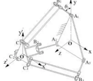
Fig.2 The Delta mechanism of Omega.7
Fig.3 Wrist joint mechanism and holding jaw mechanism
2.2 Structure analysis of the Delta mechanism
The Delta mechanism is composed of static platform, moving platform and the three links which connected the static platform and the moving platform[9], and the mechanism sketch of Delta mechanism is shown in Figure.4, as is shown in it, the structure of each branched chain are same, and it series connected of active arm and driven arm.The active arm is a planar linkage with rotation joint on the two sides, the driven arm is a parallelogram mechanism, and the two parallel links in the parallelogram mechanism of the driven arm connect the active arm and the moving platform through the rotation joints. The three parallelogram mechanisms in the Delta mechanism restrict all the rotations, so the motion of moving platform is a pure translation in the space.
origin O to the pointA1, the positive direction of xaxis is horizontal to the right, and the direction of z axis can be defined according to the right-hand rule.
Fig .5 The space coordinates of Delta mechanism
The radius of the center circle of the base shaft is denoted by r1,and is the radius of the center circle of the
moving platform is denoted by r2, l1andl2 respectively represent the length of the active arm and the driven
arm.
1
i
OA r;O C' i r2;A Bi i l1;B Ci i l2; (1)
The angle between the active arm A Bi i and plane
xoy
is denoted byi,
x y z, ,
is the coordinate ofthe center point of the moving platform in the coordinates O xyz .
III.
The position analysis of Delta mechanism
3.1 The inverse kinematics analysis of Delta mechanismThe analysis of inverse kinematics is to solve the input angles
1, 2, 3
of the active arm, as the centerposition coordinates
x y z, ,
of the moving platform are provided.[10~11]The projection relations of static platform in planar xoy and the projections relations of moving platform in planar x o y' ' 'are shown in Figure.6 and Figure.7 respectively. Let ibe the angle between OAiand the
positive direction of xaxis, and the angle between O A i and the positive direction of xaxis equalsi,
1, 2,3
i .
Fig.7 The projection relation of moving platform
It can be derived from the geometric relation: 2
3 6
i i
(2)The position vector of point Ai in the static platform:
1 cos sin 0 i i i OA r (3)
The position vector of point Bi in the static platform:
1 1
cos cos cos
sin cos sin
0 sin
i i i
i i i i i i i
i
OB OA A B r l
(4)
The position vector of point Ci in the static platform:
2
cos
' ' sin
0
i
i i i
x
OC OO O C y r
z (5)
The vector loop relationship can be established by the geometric relation:
i i i i
OCOB B C (6) The equation can be established according to the constraint of rod lengthB Ci i l2:
2 2
2 1 1 2 1 1
2 2
1 2
cos
cos
cos
cos
sin
sin
cos
sin
sin
i i i i i i i i
i
x
r
r
l
y
r
r
l
z l
l
(7)
Expand the formula 7 and obtain:
2 2 2 2 2 2
2 1 1 2 2 1
1 2 1 1
( ) 2( )( cos sin )
2 ( cos sin ) cos 2 sin 0
i i
i i i i
x y z r r l l r r x y
l r r x y zl
(8)
By using the trigonometrical transform:
2
2 2 2
2 tan 1 tan tan
2 2 2
sin ;cos ; tan ;
1 tan 1 tan 1 tan
2 2 2
a a a
a a a
a a a
(9)
Transform the formula 8 into the equation for ti( tan
2
i i
t ):
2 2 2 2 2
2 1 2 1 1 2 1
2 2 2 2 2 2
2 1 2 1 1 2 1
1
[ ( )] 2[ ( )]( cos sin )
{ [ ( )] 2[ ( )]( cos sin )}tan
2
4 tan 0
2
i i
i i i i
x y z l l r r l r r x y
x y z l l r r l r r x y
zl (10)
Transform the formula 10 into the quadratic equation for ti:
2 0
i i i i i
According to the formula of root of quadratic equation:
2 4
2
i i i i
i
i
b b a c
t
a
;
When the center position coordinate
x y z, ,
of the moving platform of the Delta mechanism are provided, according to i 2 arctanti, the inverse positional problem of two positions can be calculated, then the unique solution can be determined by the initial position and the continuous change rule of active arm’s movement.3.2 The forward kinematics analysis of Delta mechanism
The forward kinematics analysis of Delta mechanism is to solve the coordinate
x y z, ,
of the center position of moving platform, in the case of the active arm’s input angle
1, 2, 3
are provided.Because of thecomplexity of the parallel mechanism, it is difficult to get the analytic solution, so the question of solving forward kinematics is generally converted to the question of obtaining the numerical solution of nonlinear equations. In this paper, the forward kinematics solution is solved by the Newton iteration method.[12]
Equation 7 is the constraint equation established based on the Delta mechanism’s vector loop and the three elements nonlinear equations of variables x, y, z can be got by equation 7:
2 2 2 2
1 1 1 2
2 2 2 2
2 2 2 2
2 2 2 2
3 3 3 2
( ) ( ) ( ) 0;
( ) ( ) ( ) 0;
( ) ( ) ( ) 0;
x A y B z C l
x A y B z C l
x A y B z C l
(13)
Some these are replaced byAi (r2 r1 l1cos ) cosi i;Bi(r2 r1 l1cos )sini i;Ci l1sini;
Letf x y zi( , , )(xAi)2(yBi)2 (z Ci)2l22 ,
1 2 3
T
f f f
F ; the nonlinear equations 13 can be expressed as follows in further steps:
( )0
F x (14)
Let F x( )be the Jacobian Matrix of the vector function F x( )(namely the derivative of F x( )), F x( )1 is the inversion of the Jacobian Matrix of F x( ).
1 1 1
1 1 1
2 2 2
2 2 2
3 3 3
3 3 3
( ) ( ) ( )
2( ) 2( ) 2( )
( ) ( ) ( )
( ) 2( ) 2( ) 2( )
2( ) 2( ) 2( )
( ) ( ) ( )
f f f
x y z
x A y B z C
f f f
x A y B z C
x y z
x A y B z C
f f f
x y z
x x x
x x x
F x
x x x
(15)
Apply the Newton method of the single equation on equation 14, then we can obtain the Newton iterative method for nonlinear equations:
( 1) ( ) ( ) 1 ( )
( ) ( ), 0,1, ,
k k k k
k
x x F x F x (16)
Suppose (k1) ( )k ( )k
x x x , the linear equation F x( ( )k )x( )k F x( ( )k )
need to be solved to find out the vector of ( )k
x , then let (k1) ( )k ( )k
x x x , each step includes the calculations of vector F x( ( )k) and the
matrix F x( ( )k ).
IV.
Velocity and acceleration analysis of Delta mechanism
4.1 Velocity analysis of Delta mechanismAfter derivation calculus to formula 8, we can get[13]:
2 1 1 2 1 1 1
2 1 1
[ ( cos ) cos ] [ ( cos ) sin ] ( sin )
[( cos sin ) sin cos ]
i i i i i
i i i i i
x r r l x y r r l y z l z
x y r r z l (17)
Suppose Di[( cosx iysini r2 r1)sinizcos ]i l1, then transform formula 16 as a matrix:
1 1 1 1 1
2 2 2 2 2
3 3 3 3 3
0 0 0 0 0 0
x A y B z C x D
x A y B z C y D
x A y B z C z D
(18)
Denoted by:
1 1 1
2 2 2
3 3 3
x
x A y B z C
J x A y B z C
x A y B z C
、 1 2 3 0 0 0 0 0 0 q D J D D
; x
x y z
T ;1 2 3
T
q ;
Formula 17 can be expressed as:
x q
J x J q (19)
Then forward solution of velocity of Delta mechanism can be expressed as:
1
Jx Jq
x q (20)
The inverse solution of velocity of Delta mechanism can be expressed as:
1
Jq Jx
q x (21)
4.2 Acceleration analysis of Delta mechanism
After two-order derivation calculus to formula 19, we can get:
x x q q
J x J x J q J q (22)
Then forward solution of acceleration of Delta mechanism can be expressed as:
1
( )
x Jx Jqq Jqq Jxx (23)
The inverse solution of acceleration of Delta mechanism can be expressed as:
1
( )
Jq Jx Jx Jq
q x x q (24)
Of which:
1 1 1
2 2 2
3 3 3
x
x A y B z C
J x A y B z C
x A y B z C
, 1 2 3 0 0 0 0 0 0 q D J D D , 1 1 1 1
cos sin ;
sin sin ;
cos ;
{( cos sin ) sin [( ) ]cos }
i i i i
i i i i
i i i
i i i i i i i i
A l
B l
C l
D x y z r z l
dynamics and workspace.
VI.
Acknowledgement
The paper is financially supported by Shanghai University of Engineering Science.
References
[1] Yang Liying. Research on Robot Teleoperation System Based on Force Feedback [D]. Guangzhou: South China University of Technology, 2011: 1-11
[2] Song Aiguo. Force Telepresence Telerobot(1):Review of the history and development[J]. Journal of Nanjing University of Information Science and Technology: Natural Science Edition,2013,5(1):1-19
[3] Li Jiajia. A Review of the Research and Applications of Force Feedback Devices Based on Virtual Reality[J]. Mechanical Science and Technology for Aerospace Engineering. 2011,30(7):1107-1111
[4] Zhang Yan. The Research And Development of Virtual Surgery Device with Force Feedback [D]. Shanghai, Shanghai Jiao Tong University, 2008:1-14
[5] Gao Xiaoxue.Research on Kinematic and Dynamic Performance of 3-PPR Planar Parallel Mechanism [D].Taiyuan: North University Of China. 2014:3-6
[6] Ai Qinglin.Review of Kinematic and Singularity of Parallel Manipulator [J].Journal of Zhejiang University. 2012. 46(8):1345-1347
[7] Introduction Handbook of Force Dimension’s haptic feedback device Omega.7. Beijing. 2010
[8] Gao Feng. The Study of Haptic Representation System of Teleoperation Mis Robot [D]. Zhengzhou: Henan University of Technology. 2011:18-24
[9] Peng Yu.Digital Design and Workspace Analysis of Delta Robot [D].Wuhu: Anhui Polytechnic University.2014:13-16 [10] Lei Gaili. Inverse Kinematic Analysis for Delta Parallel Mechanism [J].Equipment Manufacturing Technology.2011.3:16-18 [11] Fu Zhiyu. Application Research of Virtual Reality Haptic Feedback System [D].Shanghai: Shanghai University of Engineering
Science,2015:11-12
[12] Li Qingyang. Numerical Analysis [M].Beijing:Tsinghua University Press. 2012