Cooperative Adaptive Cruise Control: An
Intelligent Mobility Solution with Adaptive Cruise
Control
Rishikesh Pilangad Harikrishnan Assistant Professor
MITS, Varikoli P.O, Puthencruz, Ernakulam, Kerala-682308, India
Abstract
Research is booming in the field of vehicle automation with prime motivation in improving driving comfort. The road traffic issues are booming to a new height as the number of vehicles is increasing day by day. Driving through an urban area is tiresome. If a control system can take you through this traffic congestion it will be a boon to car drivers whose life is depending on mobility. Cruise Control (CC) [1] was the first driver assistant launched into the market which can monitor the speed of the car. Later on CC was improved to Adaptive Cruise Control (ACC) [1] with additional radars [11] and cameras. The entire control system has been remodelled in such a way that even the system takes the control of the car in locations where it is stressful to manoeuvre. Things moved into a new breed of control system on advancing ACC to Cooperative Adaptive Cruise Control (CACC) [2] [3]. The concept of platoon with inter-vehicle communication system and utilizing GPS [15] for precise manoeuvring along with String Stability has improved the vehicle density with drastic reduction in road accidents. The report gives an insight to CACC through ACC.
Keywords: ACC, CACC, Vehicle Following, Vehicle-Vehicle Communication
________________________________________________________________________________________________________
I. INTRODUCTION
Driving in heavy traffic is hard work. The driver needs to concentrate at all time to respond quickly to new situations and react by braking or accelerating. With Adaptive Cruise Control (ACC), the driving will be more relaxed. ACC can take the pressure of the driver during the journey by adapting the speed of the vehicle to the flow of the traffic. [1]
The driver selects the desired speed and sets the distance to be maintained from the vehicle ahead. This distance can be set at several levels, adapting to the driving situation and individual driving style. Long range radar sensor is used to monitor the driving situations in-front of the vehicle.
Fig. 1: Long Range Radar [8]
Once the road ahead is clear, ACC automatically accelerates the vehicle to the speed that is preset by the driver. ACC can support different types of traffic conditions like harmonious or discord traffic flow on the roads. Even if the ACC is switched ON to monitor the driving, it is still the driver’s responsibility to monitor the distance and speed relative to the vehicle ahead at all times. The drivers have the priority to turn-off or override the ACC function at any time. The standard ACC can be activated from speeds of around 30kmph upward and can support the driver particularly on cross country journeys or on freeways up-to a speeds of around 200kmph. [1]
The ACC’s stop and go version is also active at speeds less than 30kmph, right down to vehicle stand still. The system can maintain the set distance to the preceding vehicle even at low slow speeds and can break down to complete vehicle stand still. When the vehicle in-front moves forward within a few seconds, the ACC vehicle follows automatically. When waiting times are longer, the driver needs only to reactivate the system by a slight throttle to return to ACC mode. In this way “ACC stop and go” [1] is a boon to drivers who spends most of their time on roads with heavy traffic and traffic jams. [1]
Both ACC versions can be realized by using just one long range radar sensor. The tried and tested ACC functions can be further optimized by intelligent networking with surround sensors already installed in the vehicle or by integrating additional video or radar sensor technology. This enables the ACC speed range to be extended from 200kmph to 250kmph and offers increased dynamics when driving off from stand still. [1]
The next advancement in ACC is Cooperative Adaptive Cruise Control (CACC). This is an add-on type of ACC with inter vehicle communication system to bring up a group of vehicle to the Cruise Control strategy with optimized speed and to reduce the traffic congestion. The flow from ACC to CACC is described in this paper.
Fig. 2: Driver assistance systems [1] II. LITERATURE REVIEW
Vehicle intelligence is now becoming an inseparable part in automobile technology. Artificial intelligence with neural networ ks is taking the place of intelligent driving as assistance to automobile drivers. But there are areas in which human intelligen ce has to overdrive the computing capability of artificial intelligence to avoid disasters. Many methods have been implemented in automatic maneuvering to assist the driver in order to avoid fatigue due to long duration drive.
The first of its kind is HIL (Hardware in the Loop) [2] as a control for a fleet of cars. As the advancement in wireless technology reached a satisfactory level, it was tried for platooning vehicles for a Cooperative Adaptive Cruise Control (CACC ) approach. Being a decentralized approach, there were always problems while an algorithm is run in vehicle management between vehicles in a lane. In this case each vehicle can communicate with each other, but only with the vehicles in fleet. Now this system is a dynamical network system. Hence, it is always a tedious task for the developers to create an asymptotically stable network control system [2]. The research is going on to develop an algorithm having String Stability [2].
The traffic dynamics will vary according to the location like highways and city areas. The vehicles equipped with CACC will respond according to the algorithm with which it is programmed. This approach is not suitable as the inter vehicle distance must be altered in different road conditions in order to cope up with the vehicle density at different locations. Also it must be varied according to the type of drivers as the response time varies from 0.8sec to 1sec from aggressive young drivers to aged drivers. So a flexible approach is mandatory to makeup this difference. [3]
FAST (flexible agent-based simulator of traffic) [3] is a simulator model to study the response of vehicles fitted with CACC at different traffic conditions. It is an object-oriented micro simulator with java platform and different road conditions with variable road traffic conditions. In this they utilized a separate lane known as HOV (high-occupancy vehicle) for vehicles fitted with CACC. The result was fruitful with very high vehicle flow with least traffic congestion. [3]
and the distance between the vehicles are optimized according to the traffic conditions and the vehicles in the platoon will be updated with the vehicle parameters and other traffic parameters for a safe movement with least congestion.
The aim of developing an algorithm is to converge the result to a satisfactory output and to make the error in a closed loop system to zero level. PID controllers [13] are generally used in cruise control systems and adaptive cruise control systems. The difference between these two controls is the type of settings that it relies on and the mode of operation.
In the case of ACC equipped cars the dynamics has to be modified according to the traffic flow. For that a sliding mode approach is followed. A variable S will be added to the feedback loop in such a way that the result always converges to a zero error possibility that too with minimal time delay. This creates a good response and an active adaptation capability for the vehicle. [4]
To design controllers for maintaining cruise control is not an easy task. The vehicle dynamics will be different during acceleration and braking. The throttle response will vary according to the type of transmission used in the car. The concept of a hybrid controller that can adjust the scheme of operation according to the requirement with least effort is gaining high priority in vehicle automation. From the conventional PID controller a modified version, FOC (fractional-order control) [5] that can switch between controllers according to the dynamics has gained importance in the design of CACC.
III. ACC IN BRIEF
ACC is one among the two subsystems in CACC. The ACC in CACC system is having the control to the braking system of the CACC equipped vehicle also to the steering angle and yaw rate sensor to detect the lane on which the car is moving and to detect road curves. The communication subsystem, the second subsystem in CACC, will be handling the data transfer among the vehicles in the pool.
The ACC subsystem is equipped with a RADAR sensor along with LIDAR [12], stereoscopic camera, tyre speed sensor, and brake pad monitor sensor for advanced monitoring. The RADAR sensor determines the speed and distance of the vehicle ahead. If the calculated distance is greater than the desired one the vehicle is accelerated to achieve the desired distance and speed is achieved and if the distance between the vehicles is less than the desired distance, the vehicle in consideration is decelerated by reducing the throttle, pulling down gear and by applying brakes in worst case. The braking capability is restricted to approximately 25% of the maximum deceleration potential of the brake system (full braking) in -order to avoid sudden jerking and to ensure a soft commute.
The RADAR signals will have noise embedded on its received signal and possibilities of losses are very high. Radar performance is also diminished by rain, spray and slush. This reduces the monitoring capability as complex filtering and processing is required to the reflected signal from the preceding vehicle. In this case as a support to RADAR, stereo vision cameras with its image processing power is used. This helps in lane keeping and during road curves to determine the actual vehicle with which manoeuvring has to be done for safe commute.
The CACC feature will be beneficial in urban areas were stop-and-go traffic is a usual routine. The technology has advanced and is now equipped with the ability to stop the car completely to gain fuel efficiency, when sitting in traffic. The system re-starts the vehicle and follows the car in front when the traffic begins to move again. This type of control action will assist the driver in heavy traffic, thereby reducing fatigue.
In certain traffic situations, the driver intervention for active braking may be required to avoid collision.
IV. HARDWARE ARCHITECTURE OF CACC
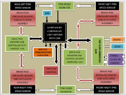
The hardware architecture of CACC is given in figure-3. The front end consists of RADAR, LIDAR and a stereoscopic camera. The navigation units are controlled by a DSP that can process the signals in real time. The tachometers connected to the tyres measures the real speed at which the vehicle is running. The signal from DSP and tyre speed controller is taken to 32-bit MCU [14] through CAN Bus [10].
The CAN Bus is a serial bus protocol for data transfer among individual systems and sensors. With CAN the automotive components can communicate on a single or dual-wire networked data bus up to 1Mbps. The CAN bus is shown in black arrow in figure-3.
Fig. 3: Cooperative Adaptive Cruise Control (CACC) Hardware Layout.
In a CACC system the difference from ACC is the presence of communication systems. There will be a GPS system for satellite navigation. The dedicated wireless communication system is used for vehicle to vehicle communication. Since there is no central unit in HIL system, the protocol used for string stability will be optimized for automotive application.
V. WORKING OF CACC
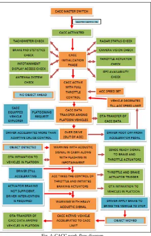
The CACC system is an autonomous driver assistive system in vehicles to reduce fatigue during long drives. The two parts in CACC are ACC and OTA (On the Air) [17] wireless communication system; can work in pool for CACC or as ACC alone. The CACC work-flow diagram is shown in figure-4.The vehicle equipped with CACC system requires three parameters (Distance, Speed and Position) of the preceding vehicle for its fluidic performance.
The distance and speed of preceding vehicle is calculated with the help of long range radars. The time difference between the transmitted and reflected signals at the radar sensor will be used to measure the distance and the effect of Doppler shift can be utilised to determine if the preceding vehicle is accelerating or decelerating.
To determine the position of the preceding vehicle (relative position), the relative angle of the preceding vehicle must be calculated. Three-beam radars can be utilized for this purpose, with which the ratio of signal amplitudes of transmitted and received signals of the individual lobes can be determined and hence the relative position of the preceding vehicle.
Fig. 4: CACC work-flow diagram
The active system in CACC the driver can control is the ACC alone, as it monitors the plant parameters and optimizes the plant for safe commute. The wireless communication subsystem that takes the platooning procedure is not the driver’s part of control. The vehicle can initialize the platooning procedure only if it is the first vehicle, and it is stabilized with ACC limits, otherwise it can join a pool with CACC. The driver can accept or reject a platoon at any time.
In the presence of objects the ACC waits for the driver response. If within the calculated safe period the driver is not responding, the ACC will initialize the braking procedure by intimating the driver with acoustic notification in the cabin. If the brake actuation is not sufficient for the situation, the ACC intimates the driver to take control of brake and warns for the emergency braking to avoid collision. Once if the object is removed the ACC automatically accelerates the car to the set speed in ACC console and platooning procedure will be initialized.
For a CACC system the entire flow diagram is valid for its operation. The add on in this case is the following vehicles will be intimated with the leading vehicle’s position, velocity, and acceleration so that the following vehicle’s ACC can optimize the parameters in its plant(car) for a safe commute in platoon. Denote by zi, vi, and ai the ith (i = 0… n−1) vehicle’s position, velocity, and acceleration, with i = 0 standing for the lead vehicle and the others being followers. δi is the spacing error between vehicles that gets pile-up which in turn ends up in improper parameter calculations. This can even lead to collisions on crucial decision making situations. In this case, human intervention that could take to over drive will solve the problem. The spacing error can be represented as, [9]
δi = zi−1 − zi − Li − hvi − d0(z0 = 0 in δ1)[9]
The dedicated wireless communication system will be doing this procedure.
VI. CONCLUSION
Vehicle intelligence is still in its nascent stage. It is not a substitute for human intelligence, but it can be utilized for assistive purpose. There will be situations in road were human intelligence can only prevent the plant from collision. So the system must be treated only as an assistive system. Since wireless communication is not fool proof, there are chances for improper data delivery, loss in data packets and delay in platooning. So it’s better for the driver to be even if the vehicle is equipped with CACC.
REFERENCES
[1] http://www.bosch-mobility-solutions.com/
[2] Umberto Montanaro, Manuela Tufo, Giovanni Fiengo,and Stefania Santini, A novel Cooperative Adaptive Cruise Control approach: theory and Hardware in the loop experimental validation, 2014 22nd Mediterranean Conference on Control and Automation (MED), University of Palermo. June 16-19, 2014. Palermo, Italy
[3] Georges M. Arnaout, Shannon Bowling, A Progressive Deployment Strategy for Cooperative Adaptive Cruise Control to Improve Traffic Dynamics.International Journal of Automation and Computing, 11(1), February 2014, 10-18
[4] Behnam Ganji, Abbas Z. Kouzani, Member, IEEE, Sui Yang Khoo, Member, IEEE, and Mojdeh Nasir, A Sliding-Mode-Control-Based Adaptive Cruise Controller, 2014 11th IEEE International Conference on Control & Automation (ICCA) June 18-20, 2014. Taichung, Taiwan.
[5] S. Hassan Hosseinnia, Inés Tejado, Vicente Milanés, Jorge Villagrá, and Blas M. Vinagre, Experimental Application of Hybrid Fractional-Order Adaptive Cruise Control at Low Speed, IEEE Transactions on control systems technology, Vol. 22, No. 6, November 2014.
[6] Vicente Milanés, Steven E. Shladover, John Spring, Christopher Nowakowski,Hiroshi Kawazoe, and Masahide Nakamura. Cooperative Adaptive Cruise Control in Real Traffic Situations, IEEE Transactions On Intelligent Transportation Systems, Vol. 15, No. 1, February 2014
[7] http://forum.a8parts.co.uk/attachment.php?attachmentid=4812&d=1348136382 [8] Karen Lie, Cruise Control System in Vehicle, Calvin College.
[9] Ge Guo, Member, IEEE, and Wei Yue, Sampled-Data Cooperative Adaptive Cruise Control of Vehicles With Sensor Failures, IEEE Transactions On Intelligent Transportation Systems, Vol. 15, No. 6, December 2014
[10] https://www.accuratetechnologies.com/CANBusInterfaces
[11] http://www.volkswagen.co.uk/technology/adaptive-cruise-control-acc
[12] http://www.digitaltrends.com/cars/lidar-lasers-and-beefed-up-computers-the-intricate-anatomy-of-an-autonomous-vehicle/ [13] http://www.facstaff.bucknell.edu/mastascu/econtrolhtml/PID/PID3.html
[14] http://www.ti.com/lsds/ti/microcontrollers_16-bit_32-bit/overview.page [15] http://rt.com/usa/ford-vp-auto-surveillance-382/
![Fig. 1: Long Range Radar [8]](https://thumb-us.123doks.com/thumbv2/123dok_us/7808661.1662197/1.612.148.464.455.670/fig-long-range-radar.webp)
![Fig. 2: Driver assistance systems [1]](https://thumb-us.123doks.com/thumbv2/123dok_us/7808661.1662197/2.612.145.470.261.442/fig-driver-assistance-systems.webp)