Finite Element Method Simulation and
Comparison of a Segmented-PM Motor and a
Whole-PM Motor
Chunyan Li*
Department of Mechanical and Electrical Engineering, Heilongjiang University, Harbin, China [email protected]
Chunhong Li and Zhongxian Wang*
Department of Physics and Electronic Technology, Liaoning Normal University, Dalian, China; Department of Mechanical and Electrical Engineering, Heilongjiang University, Harbin, China
[email protected]; [email protected]
Abstract—A permanent magnet synchronous motor (PMSM)
with rotor embedded segmented permanent magnet was analyzed. The structural features and flux weakening principle are introduced. The shape of the rotor is optimized to get a sinusoidal air gap magnetic density waveform and reduce the toque ripple. The whole-permanent-magnet (PM) motor and the segmented-permanent-magnet motor are compared from the aspects of the no-load performance, the rated load performance and the flux-weakening performance by finite element method (FEM). The theoretical analysis and simulation by FEM indicate the availability and validity of flux-weakening for the segmented-PM motor.
Index Terms—permanent magnet synchronous motor;
segmented permanent magnet; d-axis inductance; flux weakening
I. INTRODUCTION
Permanent magnet synchronous motors have been focused on in several applications such as electric vehicles, numerical control machine tool, and wind power generation systems in recent years [1-5]. Permanent magnet synchronous motors are attractive for the advantages of low volume and weight, high efficiency, and high torque-to-mass ratio. However, the excitation of the permanent magnet of the PM motor cannot be adjusted; the difficulty lies in adjusting the magnetic flux inherent in operating at constant power over broad speed range. In order to solve this problem, they control the armature current to create a magnetic flux opposite that created by the permanent magnets. This method leads to more copper loss and lower efficiency. In addition, the risk is in demagnetizing
the permanent magnet due to minus d-axis current armature reaction magnetic flux through the permanent magnets. Consequently, the scholars at home and abroad have done a lot of work on how to widen the constant power operation range. On the one hand, many special motors are presented from the point of view of motor design, such as the compound rotor [6-8], the composite field excitation motor [9], the double winding structure [10], the PMSM with variable magnetic reluctance [11] and the motor with a mechanical device [12]. On the other hand, from the point of view of motor control, the control methods are focus on vector control and direct torque control [13], such as a six-step voltage method[14] and a forward feedback flux- weakening method[15-16]. Therefore, flux weakening of permanent magnet synchonous motor is still a hotspot issues in variable frequency driving system.
In the present paper, we analyze a study of a PMSM with segmented permanent magnet,which is used for widening the flux-weakening range at constant power operation. The segmented-PM motor is analyzed by finite element method. This novelty of this segmented-PM motor lies in good adjustment of increasing or flux-weakening operation according to speed of the motor. The permanent magnet devides into several pieces, instead of a piece of wide permanent magnet. So there are some magneatic brides between the adjecent permanet magent for the segmented-PM motor. The function of the magentic bridge is to provide a magnetic flux path. The armature current is used for control the direction of the magnetic flux that go through the magnetic bridges according to speed. We can get a good flux-weakening result, which widens four times of rated speed for the segmented-PM motor by finite element method. The segmented-PM motor provides a new way to solve flux weakening for permanent magnet motor.
In the paper, firstly we introduce the motor structures and flux-weakening principle in section II, secondly optimize the rotor shape for the segmented-PM motor in
Manuscript received December 1st, 2013; revised Feburary 12, 2014; accepted Feburary 25, 2014.
This work was supported by National Science Foundation of China (Grant No. 51307045). This work was supported by Research Foundation of Education Bureau of Heilongjiang Province (Grant No.12521407 ).
section III, thirdly compare the the Whole-PM Motor and the Segmented-PM Motor from no-load performance, rated load performance and high speed performance by FEM in section IV , at last draw a conclusion of flux-weakening for the motor in section V.
II. THE MOTOR STRUCTURE
Rectangular permanent magnets embedded in the rotor are generally the most common type of the permanent magnet motor. In this paper, the permanent magnets are set in “V” shape in the rotor to provide more magnetic flux. Each pole composes of the two rectangular permanent magnets for the traditional motor, which is shown in (a) of Fig.1. The permanent magnets of the segmented-PM motor divide into several pieces, which is shown in (b) of Fig.1. There is a magnetic bridge between the adjacent segments. The torque performance at low speed and the flux-weakening performance at high speed will be discussed for the two PMSMs.
(a) The whole-PM motor (b) The segmented-PM motor Fig.1 The structure of the two motors
The torque in d-q-axis system is shown as
[ f q ( d q)d q]
T = pψ i + L −L i i
(1) Where p, f, Ld, Lq, id and iq are the pole pairs, magnetic flux provided by permanent magnets, d-axis inductance, q-axis inductance, d-axis current and q-axis current, respectively. For the d-axis inductance is smaller than q-axis inductance for most PM motors, the minus d-axis current is inputted to get a positive reluctance torque, which increase the total torque.
The speed in d-q axis is expressed as
lim
2 2
( f d d) ( q q) U
n
p ψ L i L i
=
+ + (2)
Where, Ulim is the maximum voltage. The speed
reaches to maximum speed when minus d-axis current is the maximum current, on the condition of this, the output torque is zero. The maximum speed is expressed as
lim max
lim
( f d )
U n
pψ L i
= −
(3) The magnetic bridge between the adjacent permanent- magnet segment leads to a little leakage flux but not too much. Hence, the electromagnetic torque of the whole-PM motor may be a little larger than that of segmented-PM motor due to the leakage flux. But both of the two motors can output the rated torque.
Though the magnetic bridge produces leakage flux, it helps the motor to realize increasing or
flux-weakening that depends on speed of the motor. On the one hand, the magnetic flux provided by winding current are controlled the direction as same as the magnetic flux provided by the permanent magnet, which makes sure the segmented-PM motor can output the enough torque. On the other hand, the direction is opposite, which reduces the air gap magnetic flux, the speed range is widened.
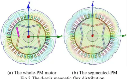
(a) The whole-PM motor (b) The segmented-PM Fig.2 The d-axis magnetic flux distribution
In addition, on the condition of same permanent magnet size, the d-axis inductance for the segmented-PM motor is larger than the whole-PM motor due to the magnetic bridge between the adjacent segmented permanent magnet. The d-axis magnetic flux distributions of the two motors are shown in Fig.2. The magnetic flux goes through the magnetic bridge and the d-axis magnetic flux is larger. Larger d-axis inductance is good for getting a higher maximum speed according to Eq. (3). So the segmented-PM motor has a wider flux-weakening range compared with the whole-PM motor. Table.1 shows the comparison of torque and maximum speed for the two motors.
TABLE I.
THE TORQUE AND SPEED PERFORMANCE
(1)The Whole-PM motor (2)The Segmented-PM motor
Ld Ld1 <Ld2 Constant torque Operation
id <0 >0
T T1>T2
Constant power Operation
id <0 <0
nmax nmax 1< nmax2
III. COMPARISION OF THE SEGMENTED-PMMOTORS WITH A CIRCULAR ROTOR AND A NON-CIRCULAR ROTOR
(a) The circular shape rotor
(b) The non-circular shape rotor
Fig.4 The no-load air gap magnetic density distribution
For PMSM, in order to get a small torque ripple, the sinusoidal air gap magnetic field is required for the input current is sinusoidal. However, the air gap magnetic density of a circular-shape rotor for PMSM is trapezoid, which is shown in (a) of Fig.4. The rotor shape is changed to improve the air gap magnetic density waveform. The motor with a non-circular shape rotor has a better sinusoidal air gap magnetic field waveform, which is more suitable for PMSM. Fig.5 verifies the motor with a non-circular shape rotor has a smaller no-load torque ripple.
Fig.5 The no-load torque of the two motors
IV. COMPARISION OF THE WHOLE-PMMOTOR AND THE
SEGMENTED-PMMOTOR
The rated data of the two motors is shown in Table.2. The no-load performance, the rated load performance and the flux weakening performance of the two motors are compared by finite element method.
TABLE II. THE RATED DATA
The segmented-
PM motor The whole-PM motor Rated power (kW) 7.5
Rated speed (rpm) 2000 Rated torque (Nm) 35.8 Rated voltage (V) 380 Rated current (A) 16.7 15 Maximum speed (rpm) 8000 <8000
A. The No-load Performance (n=2000rpm)
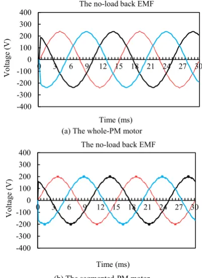
The no-load back electromotive force (EMF) is an important parameter that it reflects the quantity of the air gap magnetic density of the motor. The high ratio of the no-load back EMF to the terminal voltage is usually designed for achieving high power density at the rated speed. The no-load back EMF of the two motors is shown in Fig.6. The root-mean-square (RMS) of the no-load back EMF voltage for the whole-PM motor and the segmented-PM motor are 195V and 137.9V, respectively. The no-load back EMF of the whole-PM motor is larger than that of the segmented-PM motor. There is more leakage flux between the adjacent segment permanent magnets that is the reason for lower no-load back EMF.
(a) The whole-PM motor
(b) The segmented-PM motor Fig.6 The no-load back EMF waveform
The fast fourier transform (FFT) of the no-load back EMF of the two motors is shown in Fig.7. The fundamental frequency at the rated speed is 66.67Hz. The ratio of magnitudes of the second-harmonic wave, the third-harmonic wave and the fourth-harmonic wave to the fundamental wave magnitude for the segmented-PM motor are 0.9%, 1.67% and 0.29%, respectively. They are 2.7%, 1.71%, 0.95%, respectively, for the whole-PM
-1.5 -1 -0.5 0 0.5 1 1.5
m
agnetic dneisty
(T)
Distance The air gap magnetic dnesity
-1.5 -1 -0.5 0 0.5 1 1.5
m
agnetic dneisty
(T)
Distance The air gap magnetic dnesity
-1000 -750 -500 -250 0 250 500 750 1000
0 6 12 18 24 30
T (m
N
m
)
Time (ms)
The circular-shape rotor
The non-circular shape rotor
-400 -300 -200 -100 0 100 200 300 400
0 3 6 9 12 15 18 21 24 27 30
Voltage (V)
Time (ms) The no-load back EMF
-400 -300 -200 -100 0 100 200 300 400
0 3 6 9 12 15 18 21 24 27 30
Voltage (V)
motor. It indicates that the segmented-PM motor has a better sinusoidal waveform.
(a) The whole-PM motor
(b) The segmented-PM motor
Fig.7 The FFT of the no-load back EMF
(a) The whole-PM motor
(b) The segmented-PM motor Fig.8 The no-load torque ripple
Torque ripple affects the control accuracy of the motors. It includes the no-load ripple and the load ripple. The no-load ripples of the two motors with the same permanent-magnet width are shown in Fig.8. The magnitudes of the no-load torques of the whole-PM and the segmented-PM motor are 0.399Nm and 0.276Nm, respectively. The rated torque of the motor is 35.8Nm. The no-load ripples are 1.11% and 0.77%, respectively. The two motors are both of a small no-load ripple and the segmented-PM motor is smaller. The reason for a lower no-load ripple is a small magnetic density due to leakage
flux between the two adjacent permanent magnets at the constant torque operation.
(a) The whole-PM motor (b)The segmented-PM motor
Fig.9 The magnetic density of the motors at no-load operation:
(a) The whole-PM motor (b)The segmented-PM motor Fig.10 The magnetic flux of the motors at no-load operation
Fig.9 and Fig.10 show the no-load magnetic density distribution and magnetic flux distribution of the two motors. The magnetic density of the segmented-PM motor is a little smaller than that of the whole-PM motor. B. The Rated Load Performance (n=2000rpm)
The rated power, the rated speed and the rated torque of the motor are 7.5kW, 2000rpm and 35.8Nm, respectively. The electromagnetic torque is calculated at rated speed by the finite element method which is shown in Fig.11.
(a) The whole-PM motor
(b) The segmented-PM motor Fig.11 The rated load electromagnetic torque 0
50 100 150 200 250
0 667 1333 2000
Voltage (V)
Frequency (Hz) The FFT of the back EMF
0 50 100 150 200 250
0 667 1333 2000
Voltage (V)
Frequency (Hz) The FFT of the back EMF
-600 -450 -300 -1500 150 300 450 600
0 3 6 9 12 15 18 21 24 27 30
To
rque
(m
Nm
)
Time (ms) The cogging torque
-600 -450 -300 -1500 150 300 450 600
0 3 6 9 12 15 18 21 24 27 30
To
rque (
m
Nm
)
Time (ms) The cogging torque
15 20 25 30 35 40
0 3 6 9 12 15 18 21 24 27 30
To
rque (
N
m
)
Time (ms) The rated electromagnetic torque
15 20 25 30 35 40
0 3 6 9 12 15 18 21 24 27 30
To
rque (
N
m
)
The electromagnetic torque includes the rated torque and the no-load friction torque which is shown in the Eq. (4).
Te=TN + Tfriction (4) Where, TN, Te, Tfriction are the rated torque, the electromagnetic torque and the no-load friction torque, respectively. The no-load friction torque is hard to be calculated accurately. It is generally considered as some percent of the rated torque in project. Here, the no-load friction torque occupies 5% of the rated torque that is used for calculating the rated torque of the motors. The average of the output torque at 2000rpm for the segmented-PM motor is 35.4Nm. The load ripple of torque is 5.3%. The whole-PM motor is 35.8Nm and 5.06%, respectively. It is seen that both of the two motors can output the rated torque. However, the input current is different when they output the same rated torque. In this paper, the whole-PM motor needs 15A, but the segmented-PM motor needs 16.7A, but which are shown in Fig.12. It indicates the whole-PM motor is better at the rated speed.
(a) The whole-PM motor
(b) The segmented-PM motor Fig.12 The current at rated speed
Fig.13 shows the load back EMF of the two motors at the rated speed. The RMS of the load back EMF voltage of the segmented-PM motor and whole-PM motor are 203V and 198V, respectively. The voltage increases by 32% compared with working at no-load operation for the segmented-PM motor. The winding current of the segmented-PM motor increases the magnetic flux to provide high air gap magnetic density. It makes sure it can output enough torque at the rated speed.
(a) The whole-PM motor
(b) The segmented-PM motor Fig.13 The rated load back EMF
The magnetic density distribution and the magnetic flux distribution of the two motors are shown in Fig.14 and Fig.15. We can also see from Fig.14 that the winding current increase the magnetic flux density compared with working at no-load operation. The magnetic density of the whole-PM motor is lower due to the winding current is smaller than the segmented-PM motor when they output the same torque. Therefore, the iron loss of segmented-PM motor is larger compared with the whole-PM motor.
(a) The whole-PM motor (b) The segmented-PM motor Fig.14 The magnetic density of the motors at rated load operation
(a) The whole-PM motor (b) The segmented-PM motor Fig.15 The magnetic flux of the motors at rated load operation -40
-30 -20 -10 0 10 20 30 40
0 3 6 9 12 15 18 21 24 27 30
Cu
rren
t (A)
Time (ms) The input current
RMS=15
-40 -30 -20 -10 0 10 20 30 40
0 3 6 9 12 15 18 21 24 27 30
cu
rren
t(A)
Time (ms) The input current
RMS=16.7
-400 -300 -200 -1000 100 200 300 400
0 3 6 9 12 15 18 21 24 27 30
Voltage (V)
Time (ms) The load back EMF
-400 -300 -200 -1000 100 200 300 400
0 3 6 9 12 15 18 21 24 27 30
Voltage (V)
(a) The whole-PM motor
(b) The segmented-PM motor Fig.16 The air gap magnetic density
Fig.16 shows the air gap magnetic density distribution. The magnitude of the air gap magnetic density of the segmeted-PM motor and the whole-PM motor are 1.28T and 1.29T, respectively. it is 0.93T at no-load operation for the segmented-PM motor, which is shown in (b) of Fig.4. The d-axis current is positive, which makes sure the direction of the magnetic flux produced by winding current is as same as the magnetic flux produced by the permanent magnets.
C. The High Speed Performance (n=8000rpm)
The load back EMF is proportional to the speed. The maximum speed the motor can reach is that the load back EMF just cannot meet the requirement of the voltage balance equation. Usually the minus d-axis current is used for reducing the load back EMF and we try to keep the load back EMF lower than the motor’s terminal voltage. The torque will be zero once the minus d-axis current reaches a maximum that usually is the rated current. In order to get a good flux-weakening effect, the more reduction of the back EMF by minus d-axis current is better. Fig.18 shows the back EMF waveform with the rated minus d-axis current at 8000rpm.
Fig.17 The torque at 8000rpm (Id= -Irated)
(a) The whole-PM motor
(b) The segmented-PM motor Fig.18 The load back EMF at 8000rpm (Id=-Irated)
It is seen that there are some concaves in the sinusoidal waveform. The reason is that the minus d-axis current reduces the magnetic flux. The fundamental waveform RMS of each phase back EMF of the whole- PM motor and the segmented-PM motor are 286.2V and 178V, respectively. The back EMF of the whole-PM motor exceeds than the terminal voltage (220V) that means it cannot reach to 8000rpm. However, it is only 178V for the segmented-PM motor. It verifies the segmented-PM motor can get that speed.
(a) The whole-PM motor (b) The segmented-PM motor
Fig.19 The magnetic flux density of the motors at 8000rpm
(a) The whole-PM motor (b) The segmented-PM motor Fig.20 The magnetic flux of the motors at 8000rpm
Fig.19 and Fig.20 show the magnetic flux density distribution and the magnetic flux distribution at 8000rpm.
-1.5 -1 -0.5 0 0.5 1 1.5
m
angetic density
(T
)
Distance air gap magnetic density
-1.5 -1 -0.5 0 0.5 1 1.5
m
agnetic dneisty
(T)
Distance The air gap magnetic dnesity
-10 -7.5 -5 -2.50 2.5 5 7.5 10
0 2 4 6 8 10
T (Nm
)
Time (ms)
-600 -450 -300 -150 0 150 300 450 600
0 1.5 3 4.5 6 7.5
Voltage (V)
Time (ms) The load back EMF
-600 -450 -300 -150 0 150 300 450 600
0 1.5 3 4.5 6
Voltage (V)
The magnetic flux densities of both of them in Fig.19 are much lower than that working at no-load operation at 2000rpm showed in Fig.9, especially for the PM motor. We can draw a conclusion that the segmented-PM motor has a better flux-weakening effect from the load back EMF waveform and the magnetic density distribution. Fig.20 also shows obviously the magnetic flux distribution at 8000rpm is much fewer than that at 2000rpm.
In the q-axis system, the winding current includes d-axis current and q-d-axis current. The electromagnetic torque is related to q-axis current. The electromagnetic torque is 4Nm for the segmented-PM motor, which is shown in Fig.21.The load back EMF waveform of one phase is shown in Fig.22.
Fig.21 The electromagnetic torque at 8000rpm (id< −Irated )
Fig.22 The load back EMF at 8000rpm (id< −Irated )
The concaves in the sinusoidal waveform still exist for effect of flux weakening produced by minus d-axis current. The concaves are not symmetrical for the existence of q-axis current.
The fast fourier transform (FFT) of the load back EMF of the segmented-PM motor is shown in Fig.23. The fundamental frequency is 266.67Hz at 8000rpm. The ratio of magnitudes of the second-harmonic wave, the third-harmonic wave and the fourth-harmonic wave to the fundamental wave magnitude for the segmented-PM motor are 1.65, 88.8%, 4.4%, respectively. It is seen that the third-harmonic is serious for operation at high speed; the sinusoidal waveform of the back EMF is not as good as operation at no-load or rated load. However, the line back EMF is near to sinusoidal. Subtracting phase A to
phase B and get the line back EMF, which is shown in Fig.24. The magnitude of load line back EMF is 501V, and the load effective phase back EMF is 204.5V. The load back EMF can meet the requirement of voltage balanced equation.
Fig.23 The FFT of load back EMF at 8000rpm (id< −Irated )
Fig.24 The line load back EMF at 8000rpm (id< −Irated )
The air gap magnetic flux density is shown in Fig.25. The maximum is 0.66T. It is much lower than that working at no-load operation at 2000rpm showed in (b) of Fig.4. The air gap magnetic flux density verifies the segmented-PM motor has a good effect of flux weakening.
Fig.25 The air gap magnetic density at T=4Nm (id< −Irated )
II. CONCLUSION
The analysis and simulation by FEM indicate:
(1) The PM motor with a circular shape rotor can get a sinusoidal air gap magnetic density waveform, which is good for reducing no-load torque.
0 3 6 9 12 15
0 2 4 6 8 10
To
rque (
N
m
)
Time (ms)
The load electromagnetic torque
-600 -450 -300 -150 0 150 300 450 600
0 1 2 3 4 5 6 7 8 9 10
Voltage (V)
Time (ms) The load back EMF of A
0 50 100 150 200 250 300
0 811 1622 2432 3243 4054 4865
M
agnitude of back E
M
F
(V
)
Frequency (Hz)
FFT The FFT of phase A
-600 -450 -300 -150 0 150 300 450 600
0 1 2 3 4 5 6 7 8 9 10
Voltage (V)
Time (ms) The load back EMF of AB
-1.5 -1 -0.5 0 0.5 1 1.5
B (T)
(2) The positive d-axis current is applied to increase the air gap magnetic density to achieve a larger torque below the rated speed. The minus d-axis is applied to reduce the air gap magnetic density to achieve a wide speed range for the segmented-PM motor.
(3) The segmented-PM motor has a lower no-load back EMF, cogging torque and torque ripple but a larger rated current at the same rated torque due to more leakage flux. (4) The segmented-PM motor has a better effect of flux-weakening effect compared with the whole-PM motor. The speed range is four times wider than the rated speed.
ACKNOWLEDGMENT
This work was supported by National Science Foundation of China. Research on a new PMSM with wide flux weakening speed range and control method (Grant No.51307045). This work was supported by Research Foundation of Education Bureau of Heilongjiang Province. Research on a wide flux weakening permanent magnet synchronous motor. (Grant No.12521407).
REFERENCES
[1] Zhou Guang Xu, Tang Ren Yuan, Lee Dong Hee, Ahn Jin Woo, “Research on the Reactance Parameters of Two Interior Rotor Structures Permanent Magnet Synchronous Motor,” Proceeding of International Conference on Electrical Machines and systems.Korea, pp.1366-1370,2007.
[2] Sun Xiaodong, Chen Long,Yang Zebin. “Overview of bearingless permanent magent synchronous motors,” IEEE transactions on Industrial Electronics. 2013, 60(12):5528-5538.
[3] Li Chunyan, Kou Baoquan, “Research on Electromagnetic Force of a Large Thrust Force PMLSM Used in Space Electromagnetic Launcher,”IEEE transactions on Plasma Science.2013,41(5):1209-1212.
[4] Wang Xiaoyuan, Wang Pingxin, Yan Jiahong, Wang Gengji. “Study the effects of slotted rotor on q-axis direction on permanent magnet synchronous motor,” The 15th International conference on electrical machines and
systems. 2012,pp:1-5.
[5] Ishikawa Takeo, Seki Yutaro, Kurita Nobuyuki. “Analysis for fault detection of Vector-Controlled Permanent Magnet Synchronous Motor with Permanent Magnet Defect”, IEEE Transactions on Magnetics. 2013, 49(5):2331-2334. [6] Li Lian-Bing, Chen Peng, Shi Guang-kui, Wang Hua-Jun,
“Modeling and Simulation of Double Rotor Motor Applied to the System of Hybrid Electric Vehicle,” Electric Machines and Control. 2008,12(4):403~408.
[7] Yan Lan, He Yikang, Yang Derong. “Approach of Flux Weakening Operation Study for a BLDCM with Hybrid Rotor Structure”. Proceedings of the Chinese society of electrical engineering.2003,23(11):155~159
[8] B.J.Chalmers, R.Akmese and L. Musaba. “Design and Field-weakening Performance of Permanent-Magnet/Reluctance Motor with Two-part Rotor”. IEE proceedings Electric Power Applications,1998, 145(2): 133~139
[9] S. Hioui, L. Vido, Y. Amara, M. Gabsi, A. Miraoui. Lecrivain M, “Magnetic Equivalent Circuit Mode of a Hybrid Excitation Synchronous Machine,” The International Journal for Computation and Mathematics in
Electrical and Electronics Engineering. 2008, 27(5): 1000~1015.
[10]Tapia Juan A, Leonardi Franco, Lipo Thoms A, “A Design Procedure for a PM Machine with Extended Field Weakening Capability,” IEEE Industry Applications Society. 2002,Pitts burgh, PA, United states:1928~1935. [11]Kou Baoquan, Li Chunyan, Cheng Shukang. “Flux
weakening charactertic analysis of a new permanent magent synchronous motor used for electric vehicles,” IEEE transactions on Plasma Science.2011,38(1):511-515. [12]Nicola Bianchi, Silverio Bolognai and Brian J. Chakners.
“Salient-Rotor PM Synchronous Motors for an Extended Flux-Weakening Operation Range”. IEEE Transactions on Industry applications, 2000,(36):1118~1125
[13]Casadei Domenico, Serra Giovanni, Stefani Andrea, Tani Angelo, Zarri Luca, “DTC Drives for Wide Speed Range Applications Using a Robust Flux Weakening Algorithm,” IEEE Transactions on Industrial Electronics. 2007, 54(5):2451~2461.
[14]Kwon Tae-Suk, Choi Gi-Young, Kwak Mu-Shin, Sul Seung-Ki. “Novel Flux Weakening Control of IPMSM for Quasi-six-step Operation,” IEEE Transactions on Industry Applications. 2008, 44(6):1722~1731
[15]Jang-Mok Kim, Seung-Ki Sul, “Speed Control of Interior Permanent Magnet Synchronous Motor-Drive for the Flux Weakening Operation,” IEEE Transactions on Industry Applications.1997, 33(4):43~48.
[16]Sarikhani A, Mohammed O.A, “Demagnetization Control for reliable Flux Weakening Control in PM Synchronous Machine,” IEEE Transactions on Energy Conversion.2012, 27(4):1046-1055.
Chunyan Liwas born in Heilongjiang,
China, in 1980. She received B.E. degree in Automation from Heilongjiang University in 2003. She received the M.S. and PhD degrees in electrical engineering from Harbin Institute of Technology in 2005 and 2009.
She is currently a lecturer in Heilongjiang University. She researches on flux weakening of permanent magnet motor, linear motor and driving system. Email: [email protected]
Chunhong Liwas born in Heilongjiang,
China, in 1977. She received the M.S. degree in Communication and Information System from Dalian Maritime University in 2004. She is studying for PhD in Dalian University of Technology since 2013.09.
She is currently a lecturer in Liaoning Normal University. She researches on electrical information engineering.
Email: [email protected]
Zhongxian Wang was born in
Heilongjiang, China, in 1982. He received the M.S. degree in Control and Instrumentation from Wonkwang University in Korea in 2007. He is studying for PhD in Electrical Engineering in Harbin Institute of Technology since 2011.09.
He is currently an engineer in Heilongjiang University. He researches on permanent magnet synchronous motor and driving system.