Analysis and Design of a Filestream Based English
Language Learning System
Mohamed R. Mhereeg
1*, Asma G. Tawil
21 Faculty of Information Technology, University of Tripoli, Tripoli, Libya.
2 Faculty of Engineering Technology, Institute of Computing Technology, Janzoor, Tripoli, Libya.
* Corresponding author. Tel.: 00218918234600; email: [email protected] Manuscript submitted March 5, 2015; accepted May 3, 2015.
doi: 10.17706/jcp.10.4.268-283
Abstract: The paper discusses the feasibility of constructing a SQL Server FILESTREAM based English
language learning system (ELLS). The paper focuses on the analysis and design phase of the system. It explains the prospect of storing and managing unstructured data (e.g. Images, video, Word, Excel, PDF, MP3, etc) for educational purposes using FILESTREAM technique provided by SQL Server 2012, and how to maintain efficient storage and access to BLOB data. However, Storing unstructured data posed many challenges, such as how to maintain transactional consistency between the structured and unstructured data, how to manage backup, restore, and storage performance. The paper seeks to utilise the combination of SQL Server 2012 features and the NTFS (new technology file system) to overcome these issues and attempt to improve the efficiency and performance of the ELLS for children. The system also seeks to maintain the transactional consistency between the unstructured data and corresponding structured data. Several UML analysis techniques have been used to illustrate the analysis of the system requirements such as the Use Case diagrams, Sequence diagrams, Activity diagrams and Class diagrams. The database design of the system is also presented in this paper.
Key words: BLOB, ELLS, filestream, NTFS, unstructured data.
1.
Introduction
In recent years, there has been an explosion in the volume of digital data created and stored by both individuals and organizations [1] Historically, businesses have used computer systems and databases to store most of their business data in structured formats such as relational tables or fixed format files, and software applications have used these structured data stores to perform business tasks. Today however, a large proportion of an organization’s data is typically stored in documents created with productivity tools such as Microsoft Office Excel and Microsoft Office Word, and advances in digital photography, document scanning, video production, and audio formats have further extended the range of unstructured data formats that are used for business data [1]. For example, in the context of relational database systems, it refers to data that can’t be stored in rows and columns. Additionally, dramatic reductions in the cost of hardware storage and memory have significantly affected the amount and type of data that is stored in computer systems, and led to the emergence of a new generation of business application that merges traditional relational data structures with unstructured digital content [2].
needs of relational and non-relational data storage while reducing the cost of managing and building applications for that data [1].
Storing unstructured data such as text documents, images, and videos posed many challenges, such as how to maintain transactional consistency between the structured and unstructured data, how to manage backup and restore, and storage performance and scalability. Architects of applications that required the storage of binary large objects (BLOB) data could either store the data in the database or store it outside of the database with a reference stored in the database [2], [3].
This paper focuses on unstructured data and describes the FILESTREAM feature of SQL Server 2012, which allows storage of and efficient access to BLOB data using a combination of SQL Server 2012 and the NTFS (new technology file system). The study focuses also on the clarification the advantages and disadvantages of the use of this feature with choices for BLOB storage. An English language learning system has been developed in which this features has been applied. The system is intended to offer an excellent supporting material for in-class teaching, developing some language skills like reading, listening, and speaking at a certain level. The system will also allow doing tests and providing feedback to students.
2.
Requirements Analysis
Requirement analysis involves understanding the problem, establishing the system and the constraints under which the system will operate. It is one of the very vital activities in the development of a thesis/project and all later stages depend on it [4]. There are two kinds of requirements in the system:
Functional requirements
Non-functional requirements
2.1.
Functional Requirements
The system has two different types of system users: admin (Teacher) and student, each type of user has specific requirements which are described as the following
Administrator (Teacher)
Login to the system, Add users, View users, Delete users, Edit users, Add level, View level, Delete level, Edit level, Add Question, View Question, Delete Question, Edit Question, Add subject, View subject, Delete subject, Edit subject, Add test/answer, View test/answer, Delete test/answer, Edit test/answer, Add Result, View Result, Add feedback, View feedback.
Students
Login to the system, Change the password, View the numbers, View the letters, View the Lessons, View the results.
2.2.
Non Functional Requirements
Security requirements are important factors in this system as classified data will be stored in the database. User validation will be done during login to insure that the user is valid and that the user only has access to his or her permitted data. General users will only have access through the user interface.
The system will have consistent interface formats and button sets for all forms in the application, the system will also have a form based interface for all data entry and viewing formats, and will generate reports that are formatted in a table that should look like the existing manual report formats for the users.
3.
Use Case Diagrams
3.1.
Use Case Overview of the System
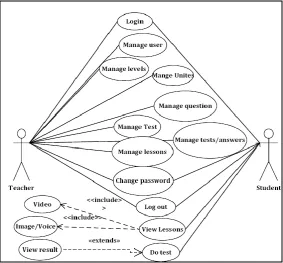
The following diagram shown in Fig. 1, clarifies the use case requirements of the proposed system. The administrator (Teacher) heads to the control panel after successful log-in to the system. In control panel, there are six sections available: User Management, level Management, question Management, Lessons Management, test/answer Management and Result Management. The student is permitted to use the user interface after a successful login to the system. There are four sections available for students: Change password, View lessons (Video, Listening), Do test, and View Results. Each section has many functions which belong to business logic layer. These functions are explained using the Use Case diagrams.
Fig. 1. Use case overview of the system.
Fig. 2. Login use case.
3.2.
Login Use Case
3.3.
Manage Users Use Case Diagram
After a successful login, the teacher can add, edit and delete students. Add, edit and delete levels, Questions, lessons (Video, Listening). Prepare tests /Answers and view results. The following diagram shown in Fig. 3, clarifies all use cases that allow creating new user, edit and delete user in the system by the teacher. An administrator (teacher) can add a new user, delete an old user, and modify user information. A new user can be added by calling “Create new user” function, followed by hitting the button “Save”. Following the same manner, a user can be deleted by calling the “Delete user” function. The “Edit” function is a very important function, because the administrator calls “Edit user” function in order to modify the user’s information.
Admin(Teacher)
Create New User
Edit user Log-in
Log-out
Delete User
Search for user
«extends»
«extends»
Log-out Admin(Teacher)
Log-in
Create New Level
Edit Level
Delete Level Check on data in Database
Search for level
«extends»
«extends» «extends»
Fig. 3. Manage users use case diagram. Fig. 4. Manage levels use case diagram.
3.4.
Manage Levels Use Case Diagram
The above diagram shown in Fig. 4, clarifies all use cases that allow creating new level, edit and delete level in the system by the teacher. There are three functions available. An administrator (teacher) can add a new level, delete an old level, and modify level. The administrator can add a new level by calling “Create new levels” function, and doing a “save” action. He also can delete a level by calling the “Delete level” function. The “modify level” function” can be operated after the “search for level “function is called.
3.5.
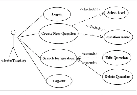
Manage Question Use Case Diagram
Admin(Teacher)
Log-in
Create New Question
Edit Question
Delete Question Log-out
Search for question
Select level
question name
«extends»
«extends» <<Include>>
<<Include>>
Fig. 5. Manage question use case diagram.
<<Include>>
<<Include>> Teacher
Log-in
Create new lesson
Log-out Video Listening Add Edit Delete Search for lesson
«extends» «extends» Select level lesson name View lesson Add Edit Delete Search for lesson
Select level lesson name View lesson «extends» «extends» <<Include>> «extends» «extends» <<In clu de> > <<Inclu de>> << Incl ud e>> <<Include>> <<In clude > > <<Include>> <<Include>>
Fig. 6. Manage lessons use case diagram.
Log-in Add test/Answers Log-out Admin(Teacher) Delete test name
question Answer 1
Answer 2
Answer 3
Answer 4
Mark
Number correct answer << Incl ude> > << Incl ud e>> <<Include>> <<Inc lude> > <<Inc lude> > <<In clud e>> <<Include>>
Search for test
«extends»
<<Include >>
Add more question «extends»
Select level
<<Inc lude>
>
Fig. 7. Manage test/answer use case diagram.
3.6.
Manage Lessons Use Case Diagram
The above diagram shown in Fig. 6, clarifies the two types of educational lessons used in the system, the use case (Create new lessons) is divided into two types of educational lessons, namely video and listening, each use case includes several functional requirements (add, edit and delete functions) as part of the functionality of the system.
Video: This section contains an explanation of a variety of lectures include (words, conversation, and grammar).
Listening: This section contains a variety of paragraphs include (sentences/words and pronunciations).
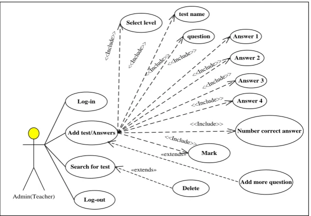
3.7.
Manage Test/Answer Use Case Diagram
“save” button. The administrator can also delete a test by calling the “delete test/answer” function that a successful call to the “search for test/answer" function.
Fig. 8. Do test use case diagram. Fig. 9. Change password use case diagram.
Manage User Manage Levels Manage Result
Log-in
Validation
Enter System
Manage Questions Manage Lessons Test/Answers
Log-out Video Listening
wrong
correc r
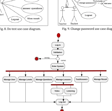
Fig. 10. Administrator (teacher) activity diagram.
3.8.
Do Test Use Case Diagram
This diagram includes all use cases that allow taking the test in the system by the students, after students finish answering the questions, they can view the results (see Fig. 8).
3.9.
Change Password Use Case Diagram
This diagram (Fig. 9) presents the use case that allows both system users the teacher and students to change the password to an appropriate one when needed.
4.
Activity Digram
4.1.
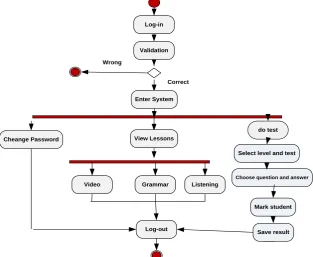
Administrator (Teacher) Activity Diagram
After a successful login, the teacher will be able to create new student accounts, add levels, questions, test/answers to a particular lesson. The teacher has to choose how to save the lessons (Video or Listening).
If the teacher chooses to save the lessons as ready lessons that means the lesson will be ready to use, the student will be able to see these lessons when they enter the system. In other hand, the lessons saved as draft lessons, only the teacher who creates them can view, edit or delete these lessons (see Fig. 10).
Choose question and answer
Cheange Password
Select level and test do test Log-in
Validation
Enter System
View Lessons
Log-out
Video Grammar Listening
Mark student
Save result Wrong
Correct
Fig. 11. Student activity diagram.
Fig. 12. Register user activity diagram.
4.2.
Student Activity Diagram
1) Change password: Changing the password requires the username, old password, New Password, and then confirm the password.
2) Do a test and view the results: Student can hit select level and test to view the questions, after the completion of the test the result is displayed.
3) View lessons: Including all types of lessons watching, Reading and listening (see Fig. 11).
4.3.
Change Password User Activity Diagram
When the teacher logs-in successfully he will be able to create new user, edit, delete user and change password (see Fig. 12).
5.
Class Diagram
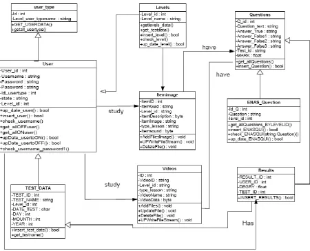
A class diagram is an illustration of the relationships and source code dependencies among classes in the unified modeling language (UML). The class used to define the methods and variables in an object, which is a specific entity in a program or the unit of code representing that entity. Class diagrams are useful in all forms of object-oriented programming (OOP). The following class diagram in Fig. 13 describes potential utility classes designed for this application. The first line on top of each class refers to the name of the class. The second segment on the stack represents the attributes of the class. The methods, which are listed on the third segment of the stack, indicate the class operation that can be used within or outside the class.
5.1.
Level Class
This class is associated with the user table in the database and has utilities to manipulate data in this table such as selection, insertion, deletion, updating and getting information about the level.
5.2.
Question Class
This class is associated with the test_question table in the database and has utilities to manipulate data in this table such as selection, insertion, deletion, updating and getting information about the question.
5.3.
Lesson_Listening Class
This class is associated with the level table in the database and has utilities to manipulate data in this table such as selection, insertion, deletion, updating and getting information about the lessons.
5.4.
Lesson_Video Class
This class is associated with the level table in the database and has utilities to manipulate data in this table such as selection, insertion, deletion, updating and getting information about the lessons.
5.5.
User Class
This class is associated with the User_type table in the database and has utilities to manipulate data in this table such as selection, insertion, deletion, updating and getting information about the user.
5.6.
User_Type Class
In this class the type of user are stored within the database to select the users Permissions.
5.7.
Test_Data Class
This class is associated with the User table in the database and has utilities to manipulate data in this table such as insertion and getting information about the test and results.
5.8.
Result Class
Fig. 13. Class diagram.
6.
Sequence Diagram
The below diagram is a model describing how groups of objects collaborate in some behavior over time, the diagram captures the behavior of a single use case, it shows objects and the messages that are passed between the objects of the system. The sequence diagram has been used in this System to show the objects interaction as the following:
6.1.
Student Sequence Diagram
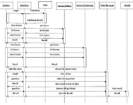
Fig. 14 below illustrates the student sequence diagram. Sequence diagrams demonstrate the behavior of objects in a use case by describing the objects and the messages they exchange. The diagrams below shows an object of Student starts the behavior by sending a message to the Interface object. Messages pass between the different objects until the object User receives the final message.
1) Interaction between the student object and the user object through (Login to the system, validate the data and return the results of the verification).
2) Interaction between the student and the lessons (video) objects, through performing the basic functions (choose the lesson name, view lesson), including giving confirmation messages for each function exists. 3) Interaction between the student object and the lessons (Listening) object, through performing the
functions (choose the lesson name, view lesson), plus giving confirmation messages for each function exists.
and answers), including giving confirmation messages for each function exists.
Fig. 14. Student sequence diagram.
6.2.
Admin (Teacher) Sequence Diagram
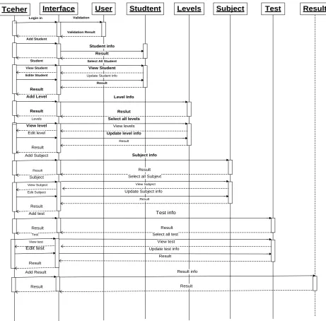
The sequence diagram in Fig. 15 illustrates a series of sequential interactions between the teacher and participating objects into the system.
1) Interaction between the teacher object and the user object through (Login to the system, validate the data and return the results of the verification).
2) Interaction between the teacher object and the student object, through perform the basic functions from (add new student, view student, modify and delete).
3) Interaction between the teacher object and the levels object through (add new levels, view level, and modify previous data), with giving confirmation messages for each function exist.
4) Interaction between the teacher object and the question object through (add new question, view question, and modify previous data), with giving confirmation messages for each function exist.
5) Interactions between the teacher object and the lessons object through (add new lessons, view lessons, and modify previous data), with giving confirmation messages for each function exist.
6) Interactions between the teacher object and the test object through (add new test, view test, and modify previous data), with giving confirmation messages for each function exist.
7.
Database Design
analyzed, and the relationships between the data are accomplished, the E-R model is established, and then the concept structure and logic structure of database are designed. Because SQL Server 2012 can be utilized with high efficiency to a variety of database queries, and can facilitate the use of stored procedures, and its graphical user interface allows intuitive and simple system and database, it was used for storage management and maintenance in this system. In addition, due to the support of web technology, SQL Server 2012 allows users to easily publish data in the database on the Windows Application.
Tceher Interface User Studtent Levels Subject Test
Login in Validation
Validation Result Add Student
Student info Result Student Select All Student
View Student View Student
Edite Student Update Student info
Result Result
Add Level
Result
Level Info
Reslut Levels Select all levels
View levels Update level info
Result View level
Edit level
Result
Result Result
Edit Subject
Select all Subjevt View Subject Update Subject info
Result View Subject
Subject
Result
Add Subject Subject info
Add test Test info
Result Result
Edit test
Select all test View test Update test info
Result View test
Test
Result
Result
Result Result
Add Result Result info
Fig. 15. Admin (teacher) sequence diagram.
7.1.
Concept Structure Design
The concept design means that abstracting the user requirements depends on the analysis of information. This step is the key to database design. The entities and their belonging attributes involved are:
1) User (User_ID, Username, Password, Security_ID, User type, User_status, Level_ID). 2) Levels (level_ID, Level_name).
Lessons: Watch (ID,VideoID, Level_id, type_lesson, lesson_name, VideoName, VideoData).
Reading and listing (ItemID,ItemGuid, Level_id, type_lesson, lesson_name, ItemDescription, ItemImage, Itemsound).
4) Test/Answers (Q_id,Question_text, Answer_1, Answer_2, Answer_3, Answer_4, Test_id, Mark, Number_correct_answer).
5) Exam (Exam_ID, Exam_name, Level_ID, Data_exam). 6) Result (result_ID, User_ID, Grade, exam_ID).
7.2.
Designing the Database Tables
This section describes the design of the system, the general structure of the database and the relationship between the database tables. It shows the design of the system from the point of view of the overall structure of the database and relationships of the database tables.
The database design of the system follows the system function analysis, according to the objectives of system requirements. The learning English Language system is based on Visual Studio and SQL Server which stores the most important data tables, such as Users (Teachers and Students) table, Levels Table, Questions table, Tests/Answers table, Results table. The Primary and Foreign keys in each data table represents their corresponding relationships.
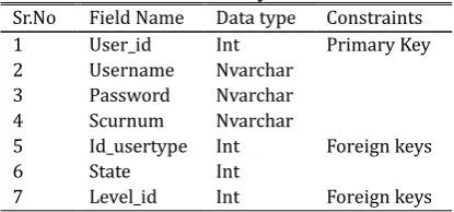
Table 1. User Entity Attributes
Constraints Data type
Field Name Sr.No
Primary Key Int
User_id 1
Nvarchar Username
2
Nvarchar Password
3
Nvarchar Scurnum
4
Foreign keys Int
Id_usertype 5
Int State
6
Foreign keys Int
Level_id 7
7.2.1.
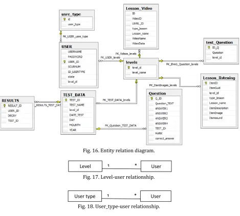
Entity relation diagram
The Entity Relationship Diagrams (ERD) has been used to organize the data in the system into entities and utilized to define the relationships between these entities. This process has allowed the analyst to produce a good database structure so that the data can be stored and retrieved in a most efficient manner [3]. Fig. 16 shows the schema of the database that illustrates how the system works and how the lessons, levels, users, questions and test/answers components are represented.
The diagram also shows the tables in the Database, and how the relationships between entities are created. This diagram is created using SQL Workbench. Rectangles represent entities; the entity name is placed at the top and the attributes are at the bottom.
7.2.2.
Database tables
The tables of the database system have also been designed, these tables are User, Levels, Questions, Lessons, Test /Answers, and Results.
7.2.2.1.
User entity
Table Description: Table 1 provides information about the user like the username, password, code security, user type, states, and level Id.
Fig. 16. Entity relation diagram.
Fig. 17.Level-user relationship.
Fig. 18. User_type-user relationship.
7.2.2.2.
Level entity
Description: Table 2 provides information about the Level_Id, level_name attributes that belong to the Levels entity.
7.2.2.3.
Test_question entity
Table Description: Table 3 provides information about the question Id, question name and level Id that belong to this entity.
Table 2. Level Entity
Constraints Data type
Field Name Sr.No
Primary Key Int
level_id 1
Nvarchar Level_name
2
Table 3. Test_Question Entity
Constraints Data type
Field Name Sr.No
Primary Key Int
Id_Q 1
Nvarchar Question
2
Foreign keys level_id
3
Fig. 19. Level-test_question relationship.
The previous table contains a primary key and a foreign key to indicate the relationship with the Level User
User type 1 *
User
table. Fig. 19 shows the one-to-many relationship between the level and Test-Question entities.
7.2.2.4.
Questions entity
Table Description: Table 4 provides information about the tests and a set of questions for each test and grades to be achieved by students.
Table 4: Qestions Entity Attributes
Constraints Data type Field Name Sr.No Primary Key Int Id_Q 1 Nvarchar Question_text 2 Nvarchar Answer1 3 Nvarchar Answer2 4 Nvarchar Answer3 5 Nvarchar Answer4 6 Foreign key Int Test_id 7 Float MARK 8 Int Correct_answer 9
The previous table contains a primary key and a foreign key to present the relationship with the Test_Data table. Fig. 20 shows the one-to-many relationship between the Test_Data and Question entities.
Fig. 22. Test_data–question.
7.2.2.5.
Test_data entity
Table Description: Table 5 provides information about the tests to be undertaken by students.
Table 5. Test_Data Entity Attributes
Constraints Data type Field Name Sr.No Primary Key Int TEST_ID 1 Nchar TEST_NAME 2 Foreign key Int Level_id 3 Datetime DATE_TEST 4
The previous table contains a primary key and a foreign key to indicate the relationship with the Level table. Fig. 21 shows the one-to-many relationship between the level and Test-Data entities.
.
Fig. 21. Level–test_data relationship.
7.2.2.6.
User_type entity
Table Description: Table 6 provides information about the user type entity.
Table 6. User_Type Entity Attributes
Constraints Data type Field Name Sr.No Primary Key Int Id 1 Nchar User_type 2
Table 7. Lesson_Listening Entity Attributes
Constraints Data type Field Name Sr.No Primary Key Int ItemID 1 Uniqueidentifier ItemGuid 2 Foreign keys Int Level_id 3 Varchar type_lesson 4 Varchar Lesson_name 5 Varchar ItemDescription 6 varbinary(MAX) ItemImage 7 varbinary(MAX) Itemsound 8 Question
TEST_DATA 1 *
TEST_DATA
7.2.2.7.
Lesson_listening entity
Table Description: Table 7 provides information about the lessons (listening) entity.
This table contains a primary key and a foreign key to present the relationship with the Level table. We have set up a table containing the column FILESTREAM. This column is of type VARBINARY (MAX) that contains the FILESTREAM feature enabled. The FILESTREAM column is created by adding the FILESTREAM attribute to the two columns called [ItemImage] and [itemsound] which are of type VARBINARY(MAX). Only VARBINARY (MAX) columns can be used for FILESTREAM storage. Fig. 22 shows the one-to-many relationship between the level and lesson-listening entities.
Fig. 22. Level-lesson_listening relationship.
7.2.2.8.
Lesson_videos entity
Table Description: Table 8 provides information about the Lessons (Visual) entity.
Table 8. Lesson_Videos Entity Attributes
Constraints Data type Field Name No Primary Key Int ID 1 Uniqueidentifier VideoID 2 Foreign key Int Level_id 3 Varchar type_lesson 4 Varchar Lesson_name 5 Varchar VideoName 6 varbinary(MAX) VideoData 7
Table 9. Results Attributes
Constraints Data type Field Name Sr.No Primary Key Int Result_Id 1 Int User_Id 2 Int Degry 3 Foreign key Int Test_Id 4
This table contains a primary key and a foreign key to present the relationship with the table Level. A table has been set up containing the column FILESTREAM. This column is of type VARBINARY (MAX) that contains the FILESTREAM feature enabled.
The FILESTREAM column is created by adding the FILESTREAM attribute to the column VideoData which is of type VARBINARY (MAX).
7.2.2.9.
Results entity
Table Description: Table 9 provides information about the results gained by students.
This table contains a primary key and a foreign key to indicate the relationship with the result table. Fig. 23 shows the one-to-many relationship between the Test_Data and Results entities.
Fig. 22. Test_data-results relationship.
8.
Conclusion
This paper has presented a novel approach to develop the English Language Learning System via utilizing the Filestream technique supported by SQL server 2012. The system proved to be successful in allowing an efficient storage and management of unstructured data (video, sound and pictures). The UML diagrams have been used successfully to achieve the analysis and design phases of the system. The outcome of this work is an attempt to maintain an efficient and effective storage and access to BLOB data available and used in the system. This will in turn allow the ELLS to operate smoothly and improve its quality and performance. This paper is one of a series of papers that will follow to present the implementation, testing, and results of the system.
Result
Test_data 1 *
References
[1] Shaun, T. J. (2011, February). SQL Server 2008 R2 FILESTREAM Design and Implementation Considerations.
[2] Lobel, L., Andrew, J., & Stephen, F. (2008). Programming Microsoft® SQL Server® 2008. New York. [3] Microsoft. (2008, July). Managing Unstructured Data with SQL Server. Retrieved June 19, 2014, from
http://download.microsoft.com/download/a/c/d/acd8e043-d69b-4f09-bc9e-4168b65aaa71/SQL200 8UnstructuredData.doc
[4] Rafique, F. & Javar, S. (2009). Implementation of Match-Making Portal (Report No. 09074). Vaxjo University, School of Mathematics and Systems Engineering.
[5] Sparx Systems. (2007). Using UML — Behavioral Modeling Diagrams. Retrieved June 23, 2014, from http://www.sparxsystems.com.au/downloads/whitepapers/UML_Tutorial_Part_2_Introduction.pdf
Mohamed R. Mhereeg was born in Gharian, Libya in 1977. He received his M.Sc. degree in
computing from Cardiff University, Cardiff, UK in 2006; the PhD degree in computing science from the University of Glamorgan, Glamorgan, UK in 2011.
Currently, he is a lecturer at the University of Tripoli, Libya. From 2007 to 2011, he was a variable hours lecturer delivering modules at both the undergraduate and M.Sc. levels with the University of Glamorgan, UK, and he was a research data analyst in University of Swansea, UK in 2011. He was an author of the book entitled: Building an autonomous and distributed multi-agent monitoring system to provide an automatic classification of end users, Germany, LAB Lambert Academic Publishing, 2013. He has a number of published articles like: The development of the multi-agent classification system (MACS) in compliance with FIPA specifications, The design of the multi-agent classification system (MACS), The implementation of the multi-agent classification system (MACS) in compliance with FIPA specifications.
Dr. Mhereeg is a member in the Fulbright International Exchange Alumni, an author in the IEEE Computer Society, and an author in the ACM Digital Library. He is also the owner of the Fulbright Visiting Scholar Program Award.
Asma G. Tawil was born in Janzoor, Libya in 1981. She received her M.Sc. degree in information technology from the Libyan Academy for Postgraduate Studies, Tripoli, Libya in 2015.