Hydraulic Field Test RIG and Evaluating Plant
Oil Performance
WB. Wan Nik
1*, F. Zulkifli
1, A. Ahmad
1, O. Sulaiman
1, S. Syahrullail
21Department of Maritime Technology, Universiti Malaysia Terengganu, 21030 Terengganu, Malaysia
2Faculty of Mechanical Engineering, Universiti Teknologi Malaysia, 81300 Johor, Malaysia
Abstract
-
Development of environmental friendly hydraulic fluid has a major influence in ecologically benign environment. This future type of oil should be non-toxic, biodegradable and ecological benign. Subsequently, it becomes crucial to recognize the sustainability of such oil in maintaining a high system performance which resulting in tremendous contribution towards machinery technology. Furthermore, the development of methods to evaluate the actual performance of hydraulic fluid has been of great interest. In this project a hydraulic test rig which incorporates LabView data acquisition system (DAQ) was built to conduct endurance test where it can be operated for up to 280 bar, running continuously with several safety features. The rig was used to test the oil and other stringent parameters, running for nearly 10000 hours at the temperature of 70 ºC under constant pressure of 70 bar and pump speed of 40 Hz. Major factors in the decrease of mechanical efficiency are thermal heat, friction, aging behaviour and contamination of the plant oil. Explained in this paper are the features of the hydraulic system built to evaluate the performance of plant oils, accompanied by some results for evaluating the suitability of the usage of plant oil as hydraulic fluid.Index Term
--
hydraulic fluid, mechanical efficiency, plant oil, volumetric efficiencyI. INTRODUCTION
Petroleum oil is a non-renewable energy resource that has been used in wide range of important applications which include transportations and power generations. Despite of its popular use, there are efforts to produce diesel oil from the used engine oil [1], aiming to use non-petroleum oil to fuel automobiles. Majority of the researchers concentrated on the use of plant oil which commonly known as biodiesel. Some examples in the study include soy, rapeseed, palm and corn oil. Less known plants are also researched such the use of jatropha oil as an alternative fuel in diesel engine [2]. Furthermore, the research on plant oil is not limited to its use as an energy resource where it has been researched to be an alternative for traditional lubricant and hydraulic fluid, i.e. bio-lubricant and bio-hydraulic fluid.
As there are evidences over the growing environmental concerns in some regions over the use of mineral-based hydraulic fluid, the plant-based hydraulic fluid is able to serve as an alternative solution to the mineral-based oil. Besides of being environmentally friendly, there are several factors that show the attractiveness of plant-based hydraulic fluid:
i. Plentiful supply and relatively low cost.
ii. Some plant oils offer excellent lubricating
properties [3], e.g. mild antiwear/extreme-pressure. performance.
iii. No adverse effects on unit performance
characteristics [4].
However, it is well known that plant oils have poor low-temperature fluidity and rapid oxidation at elevated temperatures [5-7]. In addition, plant oils are limited to their naturally inherent viscosity (kinematic viscosity at 40 ºC of 30-45 cSt depending on oil type) [4]. Furthermore, plant oils also show low static friction coefficients not depending on the kinds of wet friction materials. Since hydraulic motors of a hydraulic excavator contain wet parking brakes, the most commercially available plant oils cannot provide enough brake torque capacity to park safely. Several other disadvantages of plant-based hydraulic fluid include:
i. Rarely capable of providing adequate long-term
performance.
ii. Low oxidation resistance (can be enhanced by
addition of synthetic ester).
iii. Those with capable of meeting required
temperature and oxidation performance is at a very premium price.
Judging on the disadvantages of the plant-based hydraulic fluid and the standard requirements that need to be fulfilled, it is vital to determine the performance of the oil in a real hydraulic system. In this work, the effects from the oil degradation towards the hydraulic system efficiencies are investigated. Some of the factors, such as temperature and friction, which contribute to the degradation process, are studied by varying the pump speed and loading charge of the operation. Data obtained from the tests are used to determine the effects of speed, pressure and temperature towards the system’s volumetric, mechanical and overall efficiencies. In addition, studies on the oil viscosity and its acid value provided supporting data to the results obtained.
The authors have tested the physical and chemical performance of various plant oils. The authors managed to improve the thermal and oxidation properties of the plant oils [5]. The lubrication and rheological properties of the oil have also been evaluated [7]. This is to complement the tribological investigation done in the United States and Europe [8, 9]. These tribological results are very important in order to use plant oils as other industrial fluid [10].
emulsibility, pour point, flash point, etc. However, there exist only few types of test rigs for testing complete performance of hydraulic fluid. There is a lack of test rig available that capable to measure the long-term performance of hydraulic fluid and monitor the volumetric and mechanical efficiencies of the system. Thus, in-house hydraulic test rig was built which incorporates several interesting features and safety factors.
II. EXPERIMENTAL HYDRAULIC TEST RIG This section describes main components of hydraulic test rig and used in evaluating plant based hydraulic fluid.
A. Vane Pump
The vane used in this project consists of a rotor with passages for the vanes to slide in and out. The rotor, which contains radial slots, is splined to the drive shaft and rotates inside a cam ring. Each slot contains a vane designed to mate with the surface of the cam ring as the rotor turns. Centrifugal force keeps the vanes out against the surface of the cam ring.
B. Volumetric Efficiency (ηvp)
Volumetric efficiency indicates the amount of leakage that takes place within the pump. This involves considerations such as manufacturing tolerances and flexing of the pump casing under design pressure operating conditions. Volumetric efficiencies typically run from 82% to 92% for vane pumps.
C. Mechanical Efficiency (ηmp)
Mechanical efficiency indicates the amount of energy losses that occur for reasons other than leakage. Mechanical efficiencies typically run from 90% to 95%.
pump to delivered power actual
leakage no assuming power output pump
mp
(1)
D. Overall Efficiency (ηo)
The overall efficiency considers all energy losses and hence is defined as follows:
actualpower delivered topump
pump by delivered power actual efficiency
overall
(2)
E. Overall System
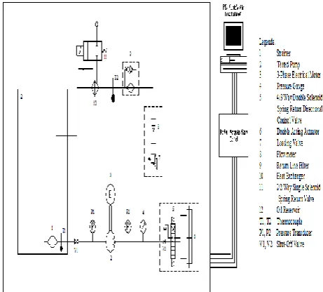
Based on the ASTM test method D 2882 philosophy, an in-house hydraulic test was designed and fabricated. Fig. 1 shows schematic drawing of the hydraulic test rig system. The hydraulic system is operated and monitored from a personal computer (PC). The hydraulic test rig comprised of an actuator, pumping system, hydraulic reservoir, cooling system, various types of controlling valves and oil conditioning components.
Fig. 1. Schematic drawing of the hydraulic test rig system
Fig. 2 shows the layout of data acquisition. Command from PC and data is obtained through serial port and RS232 cable which connects to main ADAM hardware. From the main signal conditioner, the signals are sent/received to/from motor, valves, thermocouples and other hydraulic components.
Fig. 2. Layout of data acquisition system
Fig. 3. Motor and solenoid valve circuit drawing
The system was operated at high pressure and temperature. At certain speeds, significant vibration was experienced. This affect the data obtained which is due to electrical components high sensitivity. In our project, this problem was overcome by properly insulated the signal conditioner as in Fig. 4 (our latest system).
Fig. 4. Individual power supply and signal conditioning components
The test rig has digital real-time monitoring hydraulic system which compromises of a data acquisition system and a personal computer. The computer was installed with LabView software for human-system interface, signal processing and analysis. Fig. 5 shows the entry of the system. The setting can be done here and results can be shown as graph, table, or else.
Fig. 5. First layer of programming
For example the system can be set to vary pressure from ambient pressure to the maximum pressure of 280 bar. However, we normally run the system cyclically from 10 bar to 150 bar (Fig. 6), for the safety purposes.
Fig. 6. Pressure setting
Normally we run the pump between 0 rpm to maximum speed of 1499 rpm. From the operator point of view, they operate the pump from 0 to 50 Hz (Fig. 7).
Fig. 7. Converting frequency to speed
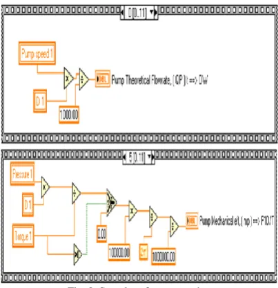
By knowing the vane pump displacement, the pump theoretical flowrate and torque are calculated directly using in-built commands (Fig. 8), which based on theoretical relationships discussed earlier in Section II. The user can visual this values graphically on the computer screen. Not only that, the user can observe the system volumetric, mechanical and overall efficiencies by a touch of screen.
Fig. 9 shows an example of data captured by the data
acquisition system. The basic parameters under
investigation are temperature, flow rate, pressure, pump speed and pump torque. With the programmes described earlier, we can determine system input and output power, volumetric, mechanical and overall efficiencies directly.
Fig. 9. An example of data captured by DAQ system
The picture in Fig. 10 shows the first version of our hydraulic test rig. At this moment we have come up with fourth generation system.
Fig. 10. First generation of hydraulic test rig
F. Efficiency Test
The test rig has been running on palm oil, coconut oil and corn oil. The oils were tested for the minimum of 1000 hours. At every 100 hour of operation, the volumetric and mechanical efficiencies were determined at various pump speed, pressures and temperatures. Pump speed was varied from 48, 45, 43, 40, 38, 35, 30, 28, 25 and 20 Hz. At each particular speed, pressure was gradually increased from 0 bar to 35, 50, 75, 100, 125, 150, 175 and 200 bar. Each set of this test was repeated for temperatures of 40, 50, 60 and 70 ºC. Volumetric, mechanical and overall efficiencies were each plotted against pressure and speed.
III. RESULTS AND DISCUSSION
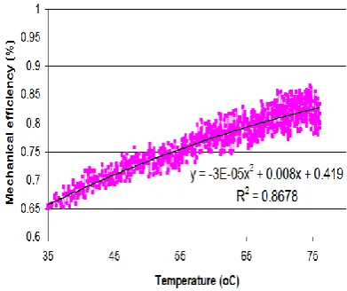
In this section, typical results from the test rig are presented and discussed. Fig. 11 shows the result when the system was operated at constant speed and pressure. The data was acquired every 10 seconds and the cooling system was disabled. However, the condition was set that if the temperature increases over 75 ºC, the pump will stop and cooling system runs immediately.
Fig. 11. Effect of temperature on performance
The turbulent flow in the 4m pipings, agitating actions in the positive displacement pump, and resistive action of pressure control valve results in increasing plant oil temperature. The snapshot graph shows that the mechanical efficiency increases with oil temperature.
With the 46 cSt plant oil, it gives resistance and results in 65% mechanical efficiency. The flow resistance gives rise to increase in temperature. This in turn results in oil losing its viscosity. The less viscous oil leads to reduce torque required to run the pump. Thus the mechanical efficiency increases.
A. Performance Analysis
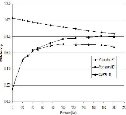
Fig. 12 shows the volumetric, mechanical and volumetric efficiencies of the system running on plant oil at constant speed. When the system was running at no load, the volumetric efficiency is almost 100% (slight error was observed due to setting in calculating the volumetric efficiency). The mechanical and overall efficiency starts at 18%. At constant speed, the loading was increased with the help of Rexroth two stage pressure control valve. This action results in increasing mechanical and overall efficiencies. However the volumetric efficiency decreases constantly with the increase in pressure. From a close observation, we found out that some of the flow goes back to the suction line, and regarded as internal leakage. Tiny drop of oil was also observed and regarded as external leakage. We ran the system up to 200 bar. The mechanical efficiency keeps on increasing, but overall efficiency drops slightly which is due to the low volumetric efficiency.
Fig. 12. Hydraulic system efficiencies
B. Volumetric Efficiency
Fig. 13 shows that volumetric efficiency decrease with pressure. The volumetric decreases due to the internal leakage and external leakage. It is assumed that the flow loss is proportional to pressure [7]. In the volumetric efficiency equation, we can see that the efficiency is the ratio between actual flow rate over theoretical flow rate.
Volumetric Efficiency vs Pressure at 70ºC
0.50 0.60 0.70 0.80 0.90 1.00 1.10
0 20 40 60 80 100 120 140 160 180 200 220 Pressure (bar)
Vo
lu
me
tri
c
Ef
fi
ci
e
n
cy
48 Hz 40 Hz 30 Hz 20 Hz
Efficiency decrease
Ef
fi
ci
e
n
cy
in
cre
a
se
Fig. 13. Volumetric efficiency characteristics
t a vp Q Q
(3)
The actual flow rate is governed by the subtraction of
Qtover flow loss, Qs. The total flow loss or the total leakage
flow increase with pressure is due to the back pressure that occurred inside the vane pump. This phenomenon increases
the internal leakage thus give a higher slip coefficient, Cs
value.
Flow loss is also affected by the oil viscosity. As the hydraulic test rig was operated at the increasing pressure, the machine temperature is increased too. With the increment of temperature, this leads to reduction in oil viscosity. Heat is contributed by the high speed motion of the proportional valve, where the internal heat from the
valve surface increases thermal load that attributes to chemical reaction which chemically altered the lubricity of hydraulic oil [7]. Besides that, when viscosity decreased, the hydraulic oil tend to be less viscous, hence it will be more easily to be slip back since there is reduction in flow resistance. Therefore, total flow loss is inverse proportional with viscosity.
C. Mechanical Efficiency
Fig.14 shows the mechanical efficiency when operated at increasing pressure. The oil temperature was kept constant at 70 ºC by energizing and deenergising cooling system automatically. The test was repeated with different motor speeds.
Fig. 14. Mechanical efficiency vs pressure
From Fig.14, it shows that mechanical efficiency does not change much with speed. Thus the effect of speed was investigated in more detail. Mechanical efficiency is related to torque loss. As the pressure is increased, more torque is required to run the pumping system.
IV.
CONCLUSIONThe design of the hydraulic system to evaluate the performance of plant based oil is presented. The system was built with concept in mind that it has several safety features and can test several conditions of actual hydraulic oil performance. The DAQ and LabVIEW software enables various variables to be displayed in many forms. This makes the system simple, easy to operate and monitored. Then endurance test was conducted by running plant oils in the test rig. Experimental results are presented to illustrate the operation and performance of the rig running on plant oil.
The main author has successfully tests the vegetable oils. At the moment the selected formulated oils are being tested in commercial hydraulic system. For further work, the authors are planning to test the formulated oil as engine oil.
V. ACKNOWLEDGEMENTS
also would like to thanks Mr Yusof and Mr Zulkarnain for their assistance.
REFERENCES
[1] R.A. Beg, M.R.I. Sarker and M.R. Pervez, “Production of diesel fuel from used engine oil”, IJMME-IJENS, Vol. 10(02), pp. 1 – 5, 2010. [2] K.M. Rahman, M. Mashud, M. Roknuzzaman and A. Al Galib,
“Biodiesel from jatropha oil as an alternative fuel for diesel engine”,
IJMME-IJENS, Vol. 10(03), pp. 1 – 5, 2010.
[3] D. Ed. Swern. “Bailey’s Industrial Oil and Fat Products.” 4th Ed. Vols.
1, 2. New York: Wiley Interscience, 1982.
[4] V. M. Cheng, A.S. Galiano-Roth, T. Marougy and J. Berezinski, “Vegetable-Based Hydraulic Oil Performance in Piston Pumps”,
Society of Automotive Engineers, Inc. SAE941079, 1996.
[5] W.B. Wan Nik, F.N. Ani and H.H. Masjuki, “Thermal stability evaluation of palm oil as energy transport media”, Energy Conversion and Management, Vol. 46(13-14), pp. 2198 – 2215, 2005.
[6] S.Z. Erhan, B.K. Sharma and J.M. Perez, “Oxidation and low temperature stability of vegetable oil-based lubricants”, Industrial Crops and Products, Vol. 24(3), pp. 292 – 299, 2006.
[7] W.B. Wan Nik, F.N. Ani, H.H. Masjuki and S.G. Eng Giap, “Rheology of bio-edible oils according to several rheological models and its potential as hydraulic fluid”, Industrial Crops and Products, Vol. 22(3), pp. 249 – 255, 2005.
[8] L.A.T. Honary, “An investigation of the use of soybean oil in hydraulic systems”, Bioresource Technology, Vol. 56(1), pp. 41 – 47, 1996.
[9] B. Kržan and J. Vižintin, “Tribological properties of an environmentally adopted universal tractor transmission oil based on vegetable oil.” Tribology International, Vol. 36, pp. 827-833, 2003. [10] Y.M. Shashidhara and S.R. Jayaram, “Vegetable oils as a potential