ISSN (e): 2250-3021, ISSN (p): 2278-8719
Vol. 08, Issue 5 (May. 2018), ||V (IV) || PP 28-34
Typical Implementation of VITERBI Decoder for efficient error
detection and correction
L V Santosh Kumar Y
1, Pyla Rajesh
2, Sekharababu Palli
3 Raghu Engineering College, Dakamarri.1,2,3Corresponding Author:L V Santosh Kumar Y
Abstract—
In the communication system, channel introduces noise and interference, which leads in distortionof transmitted signal due to which bit error may exists. To avoid this problem we proposed a Convolution encoder in the channel encoder and Viterbi decoder in the channel decoder which has error correcting capability. This paper deals with the implementation of Convolution Encoder with 2 bit code rate so it generates two bits for each bit of input data. Modified Viterbi decoder is designed to decode this encoded data without error because it has main advantage that it has the capability to detect errors and correct them effectively. We can design one particular input pattern and generate the encoded pattern using our designed encoder and it can be decoded by our Viterbi decoder without any error. Here we implemented our design using 2 bit and ½ bit code rates. Viterbi decoding for Convolutional Codes is presented here as an efficient system for reliable communication over limited noisy digital communication channels. In future it may be further extended to more bit code rates to improve its performance with less complexity.
Keywords:
Convolution encoder, Viterbi Decoder, Path metric, Trellis diagram.--- --- Date of Submission: 27-05-2018 Date of acceptance: 10-06-2018 --- ---
I.
INTRODUCTION
Communications is the study of the transmission of various data through different systems. We can transfer the information from one region to another without any loss of the data. Transmitter side source, channel encoder in that way receiver side channel, source decoders are important to have better communication.
II. CONVOLUTION ENCODER
Channel coding is the process of adding the redundant information. Convolution coding and block coding are the two main forms of channel coding. This paper deals with the implementation of convolution encoder constraint length of K=2 and with code rate=1/2.
A. Encoder design
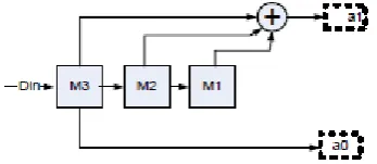
In this paper we have designed convolution encoder in the way in which that the output bits can be decoded without error. Here each input bit of data, two output bits are generated with the logic shown below. The input bits are applied serially, to m0 which represents present state, m1 and m2 represents next state. As there are two bits to represent next state, there are 4 possible combinations here is called states of the system. B. Functional description
Here input bit changes the state of encoder to generate encode data. There are two possible next states for each present state depending on the sequence. Here we have considered 3 bit register to store bits and convolute them to generate encoded data. At every clock cycle edge the input bit is loaded, operated and then shifted. The output bits pair for each input bit is transmitted to receiver, where there is a possibility of noise interference.
The convolution encoder functional block and state diagrams are shown below.
Fig. 2. State diagram of convolution encoder
The diagrammatic representation of our designed convolution encoder is shown below:
Here Output 1=a0= m (3)
Output 2=a1=m (3) XOR m (2) XOR m (1)
Table. 1. Convolution Encoder function table
Transmitted data=1001110 Encoded data=00110111101011
Convolution encoder takes input data M0, encoded this and passes through the channel. Then this encoded data is decoded by viterbi decoder and correct its error.
III. VITERBI DECODER
Viterbi decoder is designed as channel decoder in the communication system to detect the error. Here viterbi decoder is designed also for correcting the encoded date by convolution encoder at transmitter side. It receives data from channel which was sent by convolution encoder.
A. Functional block:
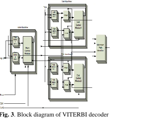
In this work Viterbi decoder has one machine and two sub machines of functional block diagram is as shown below:
B. Functional behavior of VITERBI decoder:
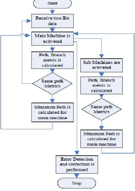
Here first main machine responds for first two bits of encoded data by calculating path metrics and branch metrics in all cases mean while both sub machines calculates the path metrics using present loaded data bits and it can be compared. It can be done before main machine completes its work because of its double clock rate. When path metrics of main machine is same then this data can be used otherwise it will be neglected. The flowchart of our designed viterbi decoder process flow is as shown below.
Fig. 4 Flow chart of VITREBI decoder
The finite state machine diagram of our designed viterbi decoder is as shown below.
Fig. 5. State diagram of viterbi decoder
Table .2.Convolution Encoder function table
The Trellis diagram of our designed Viterbi decoder process flow is as shown below.
Fig. 6. Trellis Diagram for Viterbi decoder
For receiving pairs of input data at each state decoder generates 1-bit data as decoded output which is nothing but our actual input message.
IV. SIMULATION RESULTS AND COMPARISONS
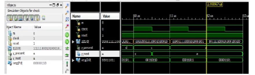
Convolution encoder and viterbi decoder functional simulation results:Consider a bit pattern ―1001110‖ to transmit in digital network. Convolution encoder generates 2 bits for each bit and this coded data transmit over channel.
Consider received data with error is given as 0111111110101. This data will be decoded by Viterbi decoder by taking 2-bits as single input and produces one bit output each combination.
Decoded data =1001110
Fig.8. Simulation results of entire Viterbi decoder
Implementation results:
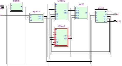
Fig. 9.RTL Schematic view of first sub machine
Fig. 10. State machine view of main machine
Fig. 12 State machine view of sub machine
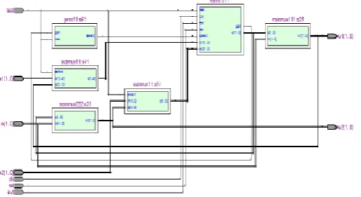
Fig. 13 RTL schematic view of entire Viterbi decoder
V. CONCLUSION
Here in this paper Convolution Encoder is designed with 2 bit code rate because it can generate two bits from each bit of input data according to our specified output functions. A modified Viterbi decoder is also designed with single clock pulse for main machine and another two sub machines which are running at double clock speed. Here advantage with this modified circuit sub machines is that they can trace out the minimum path before main machine calculating its metric avoid delay. Also another main advantage of our viterbi decoder is that it is having the capability to detect errors and correct them effectively in the communication system. Here our design is implemented using 2 bit and ½ bit code rates. In future this can be further extended to more bit code rates to improve its performance with extra machines.
ACKNOWLEDGEMENT
The authors place on record their grateful thanks to the authorities of RAGHU ENGG COLLEGE, Dakamarri, A.P, for providing facilities.
REFERENCES
[1]. A J. Viterbi, "Error Bounds for Convolutional Codesand an Asymptotically Optimum Decoding Algorithm,"IEEE Trans. lnform. Theory, vol. IT-13, pp. 260-269,Apr. 1967.
[2]. A.J.Vietrbi, ―Convoluitonal codes and their performance in communication
systems,‖IEEETrans.Commun.Technol.,volCOM-19, no.5, pp 835-848, Oct 1971.
[3]. H.S.Suresh and B.V.Ramesh ,‖FPGA implementation of Viterbi Decoder ,‖proceddings of the 6th
WESAS Int.Conf.on Electronics hardware and Optical Communication ,Corfu Island
Greece,Feb.16=19,2007.
[4]. Anuradha Kulkarni, D.S.Mantri, S.S.Wagh,‖ SOPC Based Convolutional Encoding and Viterbi
Decoding,‖ ISSN: 2231-5381.
[5]. Prof.SiddeeqY. Ameen, Ahmed S.Alenezi, ‖FPGA Implementation of modified architecture for Adaptive
Viterbi Decoder,‖SIECPC,24-26 April, 2011.
[6]. Lei –Ou Wang, Zhe-ying Li, ―Design and Implementation of a parallel processing Viterbi Decoder using
FPGA,‖ICAIE, 29-30 Oct,2010.
[7]. C.Y.Chu,Y.C.huang and A.Y.Wu.,‖Power Efficient Low latency Survier Memory Architecture for
[8]. Y.Tang,d.hu,,W.Wei,,W.lin and H.Lin,‖A Memory –Efficient Architecture for Low latenc Viterbi Decoders‖international Symposium on VLSI design,Autometion - DAT09,July ,2009.
[9]. C. B. Shung et al., ―Area-efficient architectures for the Viterbi algorithm—Part I: Theory,‖ IEEE Trans. Commun., vol. 41, pp. 636–644, Apr. 1993.
[10]. Inyup Kang, Member, IEEE, and Alan N.Willson,‖Low-Power Viterbi Decoder for CDMA mobile
terminals‖ IEEE journal of solid-state circuits, vol. 33, no. 3, march 1998.
[11]. Jiuling Tang; , "Design and FPGA implementation of a Viterbi decoder: A case study using SystemVerilog and co-simulation," Signal Processing and Information Technology (ISSPIT), 2009 IEEE International Symposium on , vol., no., pp.1-6, 14-17 Dec. 2009.