Effect of Cooling Rate on Spatial Variation in
Structural Morphology of Hypo-Eutectic (A380)
Al-Si Alloy Casting
M. Mohandass, J. Venkatesan
Department of Mechanical Engineering, Sri Venkateswara College of Engineering, Sriperumbudur, Tamil Nadu, India
Abstract— In this work, the effect of cooling rate on the spatial variation in microstructure of hypo-eutectic Al-Si (A380) alloy casting is investigated systematically. The melt is solidified with two different cooling conditions viz. conventional air-cooling and water-cooling. The heat flux through the mold wall is considered as a critical parameter to assess the cooling rate of the castings. The structural morphology of castings is characterized using Inverted Trinocular Metallurgical Optical Microscope. Microstructural examination reveals that both eutectic silicon
and CuAl2 particles of the water-cooled (high cooling rate)
casting are found to be well refined, and the size of those particles appear almost uniform throughout the casting along the longitudinal direction as compared to air-cooled counterpart.
Index Term— cooling rate, spatial variation, Al-Si alloy
casting, heat flux, eutectic silicon, CuAl2.
I. INTRODUCTION
Owing to commercial and eco-friendly necessities, it is becoming more and more important to reduce vehicle weight. For such an intention, Al-Si alloy such as A380 has been commercially used to manufacture automotive, aircraft and machine components, because of its high strength to weight ratio, outstanding castability and with high corrosion resistance [1-4]. Extensive studies have been made on Al-Si alloys for enhancing the microstructure and properties. The grain refinement leads to fine equiaxed grain structure, which in turn results in enhanced mechanical and wear properties [5]. The grain refinement can be achieved by one of the following three ways: (i) addition of grain refining elements: (ii) mechanical agitation of melt during solidification; and (iii) controlling the solidification process variables especially the cooling rate. Many researchers outlined that the refinement of microstructure, good solid solubility of alloying elements and reduced micro-segregation obtained by controlling the solidification variables may lead to an increase in fatigue, wear and corrosion resistance of Al-Si alloys [6], [7]. It is well known that the structural sensitive properties of Al-Si alloys can be improved by increasing the solidification rate with a high rate of heat extraction during the casting process [8]. The mechanical properties of Al-Si alloys can be greatly altered by changing the microstructure of the primary α-Al and the eutectic phase, which can be controlled by the solidification process [9]. The rapid cooling causes a fine eutectic structure, with small dendritic cells (grain size) and small secondary dendritic arm spacing [10], [11].
However, the disparity in rate of heat transfer from one place to another in the mold will result in the spatial variation in microstructure within the casting. This would lead to non-homogeneity in the properties of castings. To the best of knowledge of the authors, no attempt was found in the comprehensive literature review that would relate the cooling rate with the spatial variations of microstructure within the cast. Hence, an effort is made to reveal the effect of cooling rate on the spatial variations in the morphology of eutectic silicon and copper aluminide (CuAl2) particles along the
longitudinal direction of vertically mounted cylindrical shape die casting of the A380 Al-Si alloy.
II. MATERIAL AND EXPERIMENTAL PROCEDURE
Commercially available A380 Al-Si alloy was used in this experimental study. The chemical composition (as obtained from Optical emission Vacuum Spark Spectrometer analysis) of the alloy is illustrated in Table I.
Table I
Chemical Composition of A380 Al-Si Alloy Chemical
Elements Cu Si Mg Fe Mn Ni Zn Pb Ti Al Wt. % 3.4 7.8 0.18 1.1 0.41 0.3 2.64 0.25 0.18 Balance
145006-8282-IJMME-IJENS © December 2014 IJENS
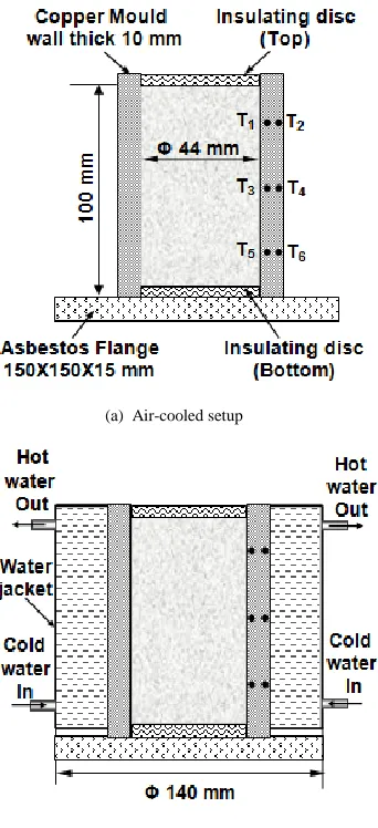
(a) Air-cooled setup
(b) Water-cooled setup
Fig. 1. Schematic diagram of mold setups
The temperature of molds were measured using K-type mineral insulated thermocouples (TC’s) of 1 mm diameter at three planes, namely plane-B, plane-M and plane-T at a distances 25 mm, 50 mm and 75 mm respectively from the bottom of the casting. The output of thermocouples were continuously fed into the computer using USB based data acquisition system and LabVIEW software. Three thermocouples namely T1, T3 and T5 are used to measure the
temperature of the mold closer to the inner wall, i.e. at about 1mm away from the inner surface. The other three thermocouples, namely, T2, T4 and T6 are used to measure the
temperature closer to the outer wall, i.e. 1 mm away from the outer surface. The top and bottom of the molds are thermally insulated with asbestos discs to ensure that the heat transfer during solidification takes place only through the mold walls. This may help to restrict the heat loss unidirectional, i.e, radially through the walls, which would simplify the application of boundary conditions during simulation works. The experimental setups of air-cooled and water-cooled castings are shown in Figs. 2 (a) and (b) respectively.
(a) Air-cooled setup
(b) Water-cooled setup
Fig. 2. Experimental setups
III. RESULTS AND DISCUSSION
A. Temperature Profile
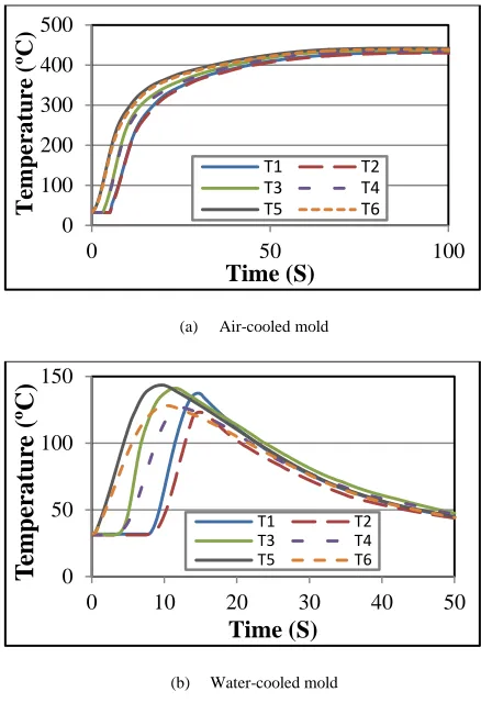
The temperature profile of the air-cooled and water-cooled molds during casting are presented in Figs. 3 (a) and (b) respectively. It is observed that the maximum temperature of air-cooled mold is around 425ºC whereas in the case of water-cooled casting it is only around 143ºC. It is also noted that the drop in temperature of the mold below 50ºC occurred within the first 50 seconds of casting process in water-cooled casting. However, as expected, it took much longer time in air-cooled casting. In practical conditions of metal castings, the heat transfer is extensively complex owing to mold filling transients, especially the temperature of mold with respect to space and time. The variation in the heat transfer rate always has a significant impact on the microstructure and mechanical behaviour of the alloys [12], [13].
B. Calculation of Heat Flux
(a) Air-cooled mold
(b) Water-cooled mold
Fig. 3. Temperature variation of molds during casting process
Hence, in this research work, it was decided to use heat flux as a critical parameter to assess the cooling rate. In particular, the value of peak heat flux is used for comparing the structural morphology of casting at different planes where the temperature of molds was actually measured.
An empirical formula based on Fourier law of heat conduction is used for the calculation of heat flux through the mold wall, which is shown in Eq.1.
𝑞 = −𝑘
𝑑𝑇𝑑𝑥(1)
Where,
q - heat flux in W/m2
k - thermal conductivity of mold material which is taken as 385 W/mºK,
dT - difference in temperature between inner and outer thermocouple readings,
dx - distance between inner and outer thermocouples in meter which is 0.04 m for all the three planes.
The calculated heat fluxes are symbolized as q1, q2 and q3
for the plane-T, plane-M and plane-B respectively, which is clearly depicted in the Fig. 4. The peak values of these heat fluxes are considered for the representation of cooling rate of different planes.
Fig. 4. Representation of heat fluxes and corresponding planes
Figs. 5 (a) and (b) show the transient variation of heat fluxes as calculated using measured temperatures for air-cooled and water-cooled castings respectively.
(a) Air-cooled casting
. (b) Water-cooled casting
Fig. 5. Mold heat flux curves
It is observed from the Fig. 5 (a) that the peak heat flux values of plane-B, plane-M and plane-T are -309.12 kW/m2, -259.3 kW/m2 and -218.7 kW/m2 respectively. At the beginning of pouring the melt into the mold, the heat transfer from the melt to the mold will take place quickly owing to the high temperature difference between the melt and the mold as the mold is at room temperature initially. However, once the temperature of the mold goes up, the heat transfer rate decreases. The mold filling and due heating decreases the temperature gradient across the mold wall and hence the heat flux significantly decreases from the bottom to top. The peak 0 100 200 300 400 500
0 50 100
T
em
perat
ure
(ºC
)
Time (S)
T1 T2 T3 T4 T5 T6 0 50 100 1500 10 20 30 40 50
T
em
p
er
at
u
re
(ºC
)
Time (S)
T1 T2 T3 T4 T5 T6 -350 -300 -250 -200 -150 -100 -50 00 50 100 150 200 250
H
eat
F
lux
(
kW/m
2)
Time (S)
q1 q2 q3 -700 -600 -500 -400 -300 -200 -100 00 10 20 30 40 50 60 70
145006-8282-IJMME-IJENS © December 2014 IJENS
heat flux at the plane-M is less by 49.82 kW/m2 compared to plane-B and the peak heat flux at the plane-T is less by 40.6 kW/m2 compared to plane-M. These huge differences in heat flux lead to the decrease in cooling rate of the casting along the longitudinal direction (from bottom to top).
It is observed from the Fig. 5 (b) that, the peak heat flux values of plane-B, plane-M and plane-T are -626.11 kW/m2, -616.3 kW/m2 and -608.2 kW/m2 respectively. The continuous supply of cooling water through the water jacket around the mold aids the heat transfer along the radial direction of the mold wall and prevents the heat dissipation in the longitudinal direction. Hence, the temperature gradient at all the three planes remains almost the same. The peak heat flux at the plane-M is less by 9.81 kW/m2 compared to plane-B and the peak heat flux at the plane-T is less by 8.1 kW/m2 compared to plane-M. It is obvious that the difference in the values of peak heat fluxes between the planes is negligible in water-cooled casting as compared to air-water-cooled casting. This produces almost the same cooling rate for all the three planes in the former case. According to Pedro R. Goulart, the solidification process variables, especially the cooling rate, have a considerable influence on the microstructural features.
B. Microstructure Evaluation
Fig. 6 shows the locations from where the specimens were extracted for microstructure evaluation. The planes from which the specimens extracted from the cast and the planes from where the temperatures were measured in the mold are more or less the same. For micrographic observations, the specimens were prepared adopting the general procedure, i.e. grinding on 2400 grit and polishing on 6, 1, 0 and 1µm diamond lap disc. Specimens were etched with a diluted HF reagent.
Fig. 6. Representation of microstructure sample locations
The microstructure of A380 Al-Si alloy composed of soft primary phase α-Al dendrites and hard secondary phase particles of eutectic silicon and copper aluminide (CuAl2).
The morphology and distribution of secondary phase particles are believed to be the influencing factors on mechanical properties of Al-Si alloys. Hence, it was decided to discuss the variations in the morphology of eutectic silicon and CuAl2. The morphology of these particles can be clearly
visualized with higher magnification and thus microstructures with 400X magnification captured using Inverted Trinocular Metallurgical Optical Microscope and presented here.
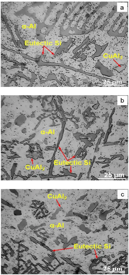
Figs. 7 (a), (b) & (c) show optical microstructures of air-cooled A380 Al-Si alloy casting for plane-T, plane-M and plane-B respectively. From Fig. 7 (c), it can be seen that the
maximum length of eutectic silicon is not exceeding 25 microns and also the CuAl2 particles appear to be finer. From Fig. 7 (b),
it is observed that both the eutectic silicon and CuAl2 particles
become coarser and the maximum length of the eutectic silicon seems to be greater than 50 microns. From Fig. 7 (c), it can be seen that the both the particles become still longer and coarser. The maximum size of the eutectic silicon seems to be more than 100 microns. The reason for the coarsening of particles from bottom to top of casting is due to the decreasing trend of cooling rate from bottom to top as discussed in the previous section. It has been reported that the variation in the nature of the cooling curve always has a significant impact on the microstructure and mechanical behaviour of the material [14]. Higher cooling rate reduces solidification time, the grain size of casting and dendrite arm spacing [15], [16].
Figs. 8 (a), (b) & (c) show microstructures of water-cooled A380 Al-Si alloy casting for plane-T, plane-M and plane-B respectively. It can be seen that in all the three planes the size of the eutectic silicon and CuAl2 particles are approximately
same. The reason for having the identical size may be attributed to the negligible variation in the cooling rate by comparing the peak values of heat flux between the three planes as discussed and quantified in the previous section.
Fig. 8. Microstructures of water-cooled casting
It has been observed that the magnitudes of peak heat fluxes in water-cooled casting are almost twice that of air-cooled in corresponding planes, refer Fig. 3. It is obvious that higher the heat flux, the greater will be the cooling rate. Hence, in all the three planes of water-cooled casting the length of the eutectic silicon particles is found to be less than 25 microns with less thickness when compared to air-cooled
casting. An increased cooling rate stimulates a large amount of nucleation sites and hence, high clusters of eutectic silicon particles were found in the α-Al matrix of water-cooled casting compared to air-cooled casting. Thus, a higher cooling rate is expected to refine the microstructural features of the Al-Si alloys in consistent with the findings elsewhere [17], [18]. A refined microstructural features will enhance the properties of Al-Si alloys, for instance refer [19], [20].
IV. CONCLUSION
Casting of A380 Al-Si alloy with water-cooling technique is a potential method for achieving the higher cooling rate. Water-cooling not only increases the Water-cooling rate, but also drastically reduces the variations in heat flux along the longitudinal direction in a vertically mounted mold. The secondary phase eutectic particles and CuAl2 particles are highly refined with an
increased heat flux which is considered as a critical parameter for assessing the cooling rate in this study. Thus, it is suggested from this work that negligible variations in heat fluxes in successive planes of water-cooled method can produce castings with identical structural morphology that could lead to cast parts with homogeneous properties.
ACKNOWLEDGMENT
The authors gratefully acknowledge the contributions from Dr. A. Venkatesan, Prof. T. S. Prasanna Kumar and Dr. Jayabal Kaliappan for their valuable technical suggestions. The authors also wish to thank Sri Venkateswara College of Engineering and the staff members, especially, Mr. M. Muthukrishnan, Mr. B. Neelakandan and E. Raman for rendering their support in conducting the experimental work.
REFERENCES
[1] Pedro R. Goulart, Jose E, Spinelli, Wislei R, Osorio and Amauri Garcia, 2006. “Mechanical properties as a function of microstructure and solidification thermal variables of Al–Si castings.” Materials Science and Engineering: A, vol. 421, no. 1-2, pp. 245-253.
[2] S.K. Pandey and C. Suryanarayana, 1989. “Structure and Transformation Behavior of a Rapidly Solidified AI-6.4wt.% Hf Alloy.” Materials Science and Engineering: A, vol. 111, pp. 181-187. [3] P. S. Mohanty and J. E. Gruzleskih, 1996. “Grain Refinemen Mechanisms of Hypoeutectic Al-Si Alloys.” Acta Materialia, vol. 44, no. 9, pp. 3749-3760.
[4] XIU Zi-yang, CHEN Guo-qin, WANG Xiao-feng, WU Gao-hui, LIU Yan-mei and YANG Wen-shu, 2010. “Microstructure and performance of Al-Si alloy with high Si content by high temperature diffusion treatment.” Transactions of Nonferrous Metals Society of China, vol. 20, no. 11, pp. 2134-2138.
[5] G.T. Abdel-Jaber, A. M. Omran, Khalil Abdelrazek Khalil, M. Fujii, M.Seki and A.Yoshida, “An Investigation into Solidification and Mechanical Properties Behavior of Al-Si Casting Alloys.” International Journal of Mechanical & Mechatronics Engineering, vol. 10, no. 4, pp. 30-35.
[6] W. Kurz, B. Giovanola and R. Trivedi, 1985. “Theory of Microstructural Development During Rapid Solidification.” Acta Metallurgica, vol. 34, no. 5, pp. 823.-830.
[7] S.G. Shabestari and H. Moemeni, 2004, “Effect of copper and solidification conditions on the microstructure and mechanical properties of Al–Si–Mg alloys.” Journal of Materials Processing Technology, vol. 153-154, pp. 193-198.
[8] R. Dasgupta, 1997, “Property improvement in Al–Si alloys through rapid solidification processing.” Journal of Materials Processing Technology, vol. 72, no. 3, pp. 382-384.
145006-8282-IJMME-IJENS © December 2014 IJENS
characteristics of intermetallic in Al–Si 319 industrial alloys.” Materials and Design, vol. 31, no. 1, pp. 343-356.
[10] H.R. Kotadia, N. Hari Babu, H. Zhang, S. Arumuganathar and Z. Fan, 2011, “Solidification Behavior of Intensively Sheared Hypoeutectic Al-Si Alloy Liquid.” Metallurgical and Materials Transactions A, vol. 42, no. 4, pp. 1117-1126.
[11] L.A. Dobrza´nski, R. Maniara, J. Sokołowski, W. Kasprzak, 2007, “Effect of cooling rate on the solidification behavior of AC AlSi7Cu2 alloy.” Journal of Materials Processing Technology, vol. 191, no. 1-3, pp. 317-320.
[12] Kurz. W., “Fundamentals of Solidification,” Trans Tech Publications (1986).
[13] Flemings, Merton C., “Solidification Processing,” McGraw-Hill Book Company (1974).
[14] T.P.D. Rajan, K. Narayan Prabhu, , R.M. Pillai and B.C. Pai, 2007, “Solidification and casting/mold interfacial heat transfer characteristics of aluminum matrix composites.” Composites Science and Technology, vol. 67, no. 1, pp. 70-78.
[15] Haizhi Ye, 2003, “An overview of the development of Al-Si-Alloy based material for engine applications.” Journal of Materials Engineering and Performance, vol. 12, no. 3, pp. 288-297.
[16] Salem Seifeddine, Sten Johansson, Ingvar L. Svensson, 2008, “The influence of cooling rate and manganese content on the β-Al5FeSi
phase formation and mechanical properties of Al–Si-based alloys.” Materials Science and Engineering: A, vol. 490, no. 1-2, pp. 385-390.
[17] L.A. Dobrzański, R. Maniara and J.H. Sokolowski, 2006, “The effect of cast Al-Si-Cu alloy solidification rate on alloy thermal characteristics.” Journal of Achievements in Materials and Manufacturing Engineering, vol. 17, no. 1-2, pp. 217-220. [18] L.A. Dobrzański, R. Maniara and J.H. Sokolowski, 2007, “The
effect of cooling rate on microstructure and mechanical properties of AC AlSi9Cu alloy.” Archives of Materials Science and Engineering, vol. 28, no. 2, pp. 105-112.
[19] M. Wierzbińska and J. Sieniawski, 2006, “Effect of morphology of eutectic silicon crystals on mechanical properties and cleavage fracture toughness of AlSi5Cu1 alloy.” Journal of Achievements in Materials and Manufacturing Engineering, vol. 14, no. 1-2, pp. 31-36.