On The Error Rate Performance Of Transmission
Modes In Lte Wireless Systems
Sonalika Bhagat, Dr. Jyoteesh Malhotra
Ece Deptt. Gndu, Rc Jalandhar, India Hod, Ece Deptt., Gndu, Rc Jalandhar, India
[email protected], [email protected]
ABSTRACT: The number of users are increasing with more and more applications and more demand. At the same time, high transmission data rates and communication reliability have become a significant requirement. The LTE and LTE-Advanced are developed by 3GPP. The LTE-Advanced features improvements in spectral efficiency, peak data rates and user experience relative to the LTE. With a maximum peak data rate of 1Gbps, LTE-Advanced has been approved by the ITU as an IMT-Advanced technology. LTE achieve its various goals through its different transmission modes that help in enhancement of data rates. In this paper, I have studied the performance of various transmission modes used in LTE and their comparison with each other is done by the use of MATLAB.
Keywords: Receive diversity, Transmit diversity, Open loop spatial multiplexing, Closed loop spatial multiplexing.
1. INTRODUCTION
The LTE and LTE-Advanced standards achieve high maximum data rates mainly as the result of incorporating many multi-antenna or MIMO techniques. Multi-antenna transmission schemes map modulate data symbols to multiple antennas ports. In the OFDM transmission scheme, each antenna constructs the resource grid, generates the OFDM symbols, and transmits the signal. In a MIMO–OFDM system, the process of resource-grid mapping and OFDM modulation is repeated over multiple transmit antennas. Depending on the MIMO mode used, this multi-antenna extension may result in a boost in data rates or an improvement in the link quality. The transmission modes exploit two main MIMO techniques: (i) transmit diversity (techniques such as Space–Frequency Block Coding, SFBC) and (ii) spatial multiplexing with or without delay-diversity coding. Transmit diversity techniques improve the link quality and reliability but not the data rate or spectral efficiency of a system. On the other hand, spatial multiplexing can bring about in a substantial boost in data rates [5].In LTE, special names are given to each transmission way. SISO is called TM1. Diversity is called TM2, MIMO but no feedback from UE is called TM3 and MIMO with UE feedback is called TM4. One of the most innovative MIMO modes in the LTE standard, responsible for its highest data rates is TM 4. This mode employs spatial multiplexing with precoding and closed-loop channel feedback. In low-mobility scenarios, a closed-loop feedback of the channel quality can lead to performance improvements [1].
2. BACKGROUND
There are 9 transmission modes used till now in LTE wireless systems. In this paper, I am going to study the first four transmission modes.
Table 1: Transmission modes in LTE
S. No. Transmission modes
Mode 1 Single-antenna transmission or receive diversity
Mode 2 Transmit diversity
Mode 3 Open loop spatial multiplexing Mode 4 Closed loop spatial multiplexing 2.1 Receive diversity
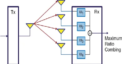
The simplest and most common multi-antenna configuration is the use of multiple antennas at the receiver side. This is often referred to as receive diversity. The most important algorithm used in receive diversity is known as Maximum-Ratio Combining (MRC). It is used within mode 1 of transmission in the LTE standard, which is based on single-antenna transmission. This mode is also known as SISO where only one receiver antenna is deployed or SIMO where multiple receive antennas are used [7]. Two types of combining method can be used at the receiver: MRC and Selection Combining (SC). In MRC, we combine the multiple received signals (usually by averaging them) to find the most likely estimate of the transmitted signal. In SC, only the received signal with the highest SNR is used to estimate the transmitted signal. MRC is a particularly good MIMO technique when, in a fading channel, the number of interfering signals is large and all signals exhibit rather equal strengths. As such, MRC works best in transmission over a flat-fading channel.
2.2 Transmit Diversity
Transmit diversity exploits multiple antennas at the transmitter side to introduce diversity by transmitting redundant versions of the same signal on multiple antennas. This type of MIMO technique is usually referred to as Space–Time Block Coding.In STBC modulation, symbols are mapped in the time and space (transmit antenna) domains to capture the diversity offered by the use of multiple transmit antennas[2]. Space–Frequency Block Coding is a technique closely related to STBC that is selected as the transmit diversity technique in the LTE standard. The main difference between the two techniques is that in SFBC the encoding is done in the antenna (space) and frequency domains rather than in the antenna (space) and time domains, as is the case for STBC. In LTE, the second transmission mode is based on transmit diversity. Transmit diversity does not help with any boost in data rate; it only contributes to the increased robustness against channel fading and improves the link quality[6].
Fig:2 Space–Frequency Block Coding
2.3 Spatial Multiplexing
In spatial multiplexing, completely independent streams of data are transmitted simultaneously over reach transmit antenna. The use of spatial multiplexing enables a system to increase its data proportionally to the number of transmit antenna ports [9]. Spatial multiplexing can directly increase the bandwidth efficiency and result in a system with high bandwidth utilization. The benefits of spatial multiplexing can be realized only if transmissions over different antennas are not correlated. This is where the multipath fading nature of a communication link actually helps the performance [11]. Spatial multiplexing transmitted over a multipath fading channel can actually enhance the performance [4].
Fig: 3 Spatial Multiplexing
i. Open-Loop Spatial Multiplexing: Open-loop spatial multiplexing has the structure that the feedback of a rank indicator (RI) in other to determine the transmission layer of UE is sent to an enhanced NodeB (eNodeB) and the feedback of a phase matrix indicator (PMI) which is the codebook matrix index for precoding is not sent[8]. It is suitable for the data channel of UE which is moving fast. Though it is stated that both the transmit diversity and open-loop spatial multiplexing is suitable for fast moving UE, practically for low SNR range transmit diversity provides better throughput. So for low SNR transmit diversity is preferred.
ii. Closed-Loop Spatial Multiplexing: It takes advantages of both spatial multiplexing and beam-forming. UE obtains the feedbacks of a RI and a PMI to eNodeB.[1] UE continuously sends feedback to the eNodeB and the selection of precoding matrix and beamforming vector depends upon this feedback. In case of fast moving UE this mode is not preferred. Because the UE is changing its position frequently and thus it impose a heavy burden on uplink. So it is suitable for the data channel of UE which is located at the center of a cell[3].
3. SIMULATION METHODOLOGY
The proposed work done here to study the different multi-antenna modes for high data rate transmission are based on the following design methodologies. For transmission mode 1 & 2, the methodology is explained by a flowchart shown below:
Set signal to noise ratio(Eb/No)
Allow modulator to generate power signals and create error rate calculator to evaluate BER
Loop over several Eb/No points & number of packets
End FOR loop for numpackets & plot results
End FOR loop for Eb/No & replot results by curve fitting and restore default stream
For transmission mode 3 & 4, the flowchart of the program is represented as under:
The parameters used to carry out the simulations for performance evaluation are tabulated below:
Table 2: Parameters with their assumed values
PARAMETERS ASSUMPTIONS
Transmission
Bandwidth 2GHz
Inter-site distance 500m
Channel Bandwiidth 1.4-20 MHz
Modulation schemes BPSK, QPSK
Multiple access
schemes SC-FDMA, OFDMA
Coverage 5-100 km with slight
degradation after 30km
BS antenna gain 15dBi
4. RESULTS & DISCUSSION
Matrix Laboratory i.e, MATLAB is the tool that being used for the simulation purposes of this paper. It was developed by Mathworks and the languages used are C, C++. Based on the simulations done as per the proposed methodology described in the previous section, the results have been obtained. Firstly, the results corresponding to mode 1 have been illustrated below in fig.4 & 5:
Fig.4: BER for different number of antennas in receive diversity
Fig.5: Comparison between Maximum Ratio Combining method and no diversity
Now, the results of mode 2 have been shown as under. Here, transmit diversity is illustrated at frame length 100 and 30 and its effects are shown:
Fig.6: Comparison between Transmit diversity and no diversity at frame length 100 and 30
0 2 4 6 8 10 12 10-4
10-3 10-2 10-1
Eb/No, dB
BER
BER for BPSK modulation in AWGN with receive diversity nRx=1 nRx=2 nRx=3 nRx=4
0 2 4 6 8 10 12 14 16 18 20 10-3
10-2 10-1
Eb/No, dB
BER
BER for BPSK modulation with MRC and No diversity (Rayleigh channel) No div (nTx=1,nRx=1) MRC (nTx=1,nRx=2)
0 2 4 6 8 10 12 14 16 18 20 10-4
10-3 10-2 10-1 100
Eb/No (dB)
BER
Effect of frame length on Transmit Diversity
No Diversity (1Tx, 1Rx) Alamouti100 (2Tx, 1Rx) Alamouti30 (2Tx, 1Rx)
Calculate SNR from EbNo for each transmission link
Initialize ZF-SIC, MMSE-SIC, ML Receiver
Update BER for loop of EbNo points
Plot results START
In fig.7 below, the comparison between the modes that is, mode 1 , mode 2 and no diversity which have been described earlier have been illustrated under:
Fig.7: Performance evaluation between No diversity, Transmit diversity and Receive diversity in terms of BER
Lastly the results of mode 3 are given in fig.8 and fig.9. In these simulations, 2x2 and 4x4 antenna configuration is taken respectively:
Fig.8: Performance evaluation between three different receivers in open loop spatial multiplexing
Fig.9: Performance evaluation between three different receivers in OLSM at more number of antennas
For mode 1, the BER performance with different number of antennas is studied. It is observed that as more no. of antennas are introduced, high performance can be achieved(figure 4). There is a combining method in receive diversity used at the receiver known as MRC(Maximum Ratio Combining). Comparison is drawn between MRC and no diversity and the results show that the introduction of diversity leads to good performance(figure 5). For mode 2, that is, transmit diversity, comparison is made with no diversity,1Tx and 1Rx at different frame lengths 100, 50 and 26(OSTBC encoder is taken in which multiple of 2 is chosen for length ; figure 6,7,8). In figure 9, performance evaluation of three diversities is studied in which MRC results show better values than the other two in terms of BER.Now, with large SNR , spatial multiplexing is designed as mode 4 called as closed loop spatial multiplexing. The results are almost similar for SM techniques. Three types of equalizers at receivers are used of which ML shows quite well performance followed by MMSE-SIC and ZF-SIC(figure 10). Mode 3 is taken with 2x2 configuration. In 4x4 configuration, ML remains best as in previous case and it is observed that with the increase in number of transmit and receive antennas with a same factor, its BER performance is also increased(figure 11).
6. CONCLUSION
The resulting simulation results show that as we go on increasing the the number of antennas from 1 to 4 its BER performance is enhanced. The maximum ratio combining method when compared with no diversity shows better results. When we consider transmit diversity also, MRC results proved to be good than others. The effects of frame length on transmit diversity is also studied and it is observed that transmit diversity does not vary much due to the reduction in frame length. It is also observed that in spatial multiplexing, when three equalizers are compared, the ML receiver is the best in performance in both 2x2 and 4x4 configurations.
0 2 4 6 8 10 12 14 16 18 20
10-3 10-2 10-1
Eb/No, dB
BER
BER for BPSK modulation with MRC and Alamouti(Rayleigh channel)
(nTx=1,nRx=1) (nTx=1,nRx=2, MRC) (nTx=2, nRx=1, Alamouti)
0 2 4 6 8 10 12 14 16 18 20
10-3 10-2 10-1 100
Eb/No (dB)
BER
2x2 Uncoded QPSK System
ZF-SIC MMSE-SIC ML
0 2 4 6 8 10 12 14 16 18 20
10-3 10-2 10-1 100
Eb/No (dB)
BER
4x4 Uncoded QPSK System
REFERENCES
[1] Ghosh, A. and Ratasuk, R. (2011) “Essentials of LTE and LTE-A”, Cambridge University Press, Cambridge.
[2] Dahlman, E., Parkvall, S. and Sköld, J. (2011) “4G LTE/LTE-Advanced for Mobile Broadband, Elsevier”.
[3] 3GPP (2011) Evolved Universal Terrestrial Radio Access (E-UTRA), “Physical Channels and Modulation Version 10.0.0. TS 36.211”, January 2011.
[4] C. Lim, T. Yoo, B. Clerckx, B. Lee, B. Shim, “Recent trend of multiuser MIMO in LTE-advanced”, IEEE Magazine, 51, 3, 127–136, 2013.
[5] 3GPP (2011) Evolved Universal Terrestrial Radio Access (E-UTRA), “Multiplexing and Channel Coding”. TS 36.212.
[6] ITU-R (2010) " Detailed specifications of the radio interfaces of international mobile telecommunications”- 2000 (IMT-2000). Recommendation ITU-R M.1457-9, May 2010.
[7] Scaglione, P., Stoica, S., Barbarossa, G. et al. (2002) “Optimal designs for space-time linear precoders and decoders”. IEEE Transactions on Signal Processing, 50, 5, 1051–1064.
[8] Browne, M. and Fitz, M. (2006) “ Singular value decomposition of correlated MIMO channels”. IEEE Global Telecommunications Conference (GLOBECOM) 2006.
[9] Jafarkhani, H. (2005) “Space-Time Coding; Theory and Practice”, Cambridge University Press, Cambridge.
[10] “Principles for the Process of Development of IMT-Advanced. Resolution” ITU-R 57, October 2007.