(UDC: 666.3-135)
Boundary element prediction of the failure resistance of thermal barrier
coating (TBC) subjected to thermo-mechanical loading
L.K. Keppas1, N.K.Anifantis2*
1Mechanical and Aeronautics Engineering Dept., University of Patras, Greece, GR-26500
2Mechanical and Aeronautics Engineering Dept., University of Patras, Greece, GR-26500
*Corresponding author
Abstract
The present study describes a sub-regional boundary element procedure for the analysis of cracked thermal barrier coatings under cyclic thermo-mechanical loads. The boundary integral equations of uncoupled quasi-static thermo-elasticity are employed to account for the transient nature of the thermal load. A crack is laid along the interface between a metallic substrate and a ceramic coating. Crack closure occurs on account of the thermal distortion and the pressure load that acts on the coating’s surface. Therefore, the heat flux between the crack faces is affected by the level of crack closure and the accurate determination of temperatures and displacements requires iterative solution of the thermal and mechanical part of the problem. The results reveal that parameters such as the coefficient of friction and thermal contact resistance have a severe impact on the predicted failure capacity of cracked structures and should be taken into consideration for the estimation of fatigue life.
Key words: Thermal barrier coating, failure resistance, boundary elements, thermo-mechanical cycling, interfacial crack
1. Introduction
Thermal barrier coatings (TBCs) are ceramic layers covering metallic surfaces, submitted to extreme thermal and chemical environments. Their aim is to provide thermal insulation and oxidation resistance at high temperatures. Numerous applications can be found in aerospace and automotive industries. The main objective when designing a TBC is the structural integrity throughout its service life. This is a serious problem for the TBC designer since the material properties mismatch, in conjunction with thermal cycling, residual stresses and environmental effects, may initiate delamination and cracking (Chen et al. 2003).
tip singular stress and thermal flux behaviours can be achieved either by using special crack tip elements or by simply increasing the mesh density near the crack tip. Several numerical studies, related to the thermal response or fracture of TBCs, have been conducted utilizing the finite element method (Nusier and Newaz 2000, Rangaraj and Kokini 2003, Hattiangadi and Siegmund 2005). However, when the crack is growing under cyclic fatigue loads, the crack growth is modelled through a number of consecutive crack steps (Prasad et al. 1996, Hattiangadi and Siegmund 2005, Yan 2007). The geometry and element mesh should be updated at each crack step in order to account for the current crack length. The boundary element method is very efficient when analyzing growing cracks because only the boundary is meshed and not the whole domain of the problem (Prasad et al. 1996, Yan 2007); therefore, the reconfiguration of geometry and mesh is easier and additionally the boundary elements exhibit very high level of accuracy in analyzing crack problems utilizing a limited number of degrees of freedom (Prasad et al. 1996, Yan 2007, Keppas et al. 2008).
The present paper presents a boundary element procedure based on the sub-regional technique and the quasi-static uncoupled theory of thermoelasticity for the analysis of interfacial crack growth in the presence of thermo-mechanical cycling. The coating’s surface is subjected to combined temperature and pressure loads and crack closure is caused by thermal distortions or mechanical compression. Therefore there is an interaction between the thermal end elastic fields around the crack tip which is treated by iterative solution of the equations of thermoelasticity. The results show significant influence of the level of thermal resistance and coefficient of friction on the behaviour of interfacial cracks and provide valuable information for the failure assessment of TBCs under cyclic loads.
2. Boundary element procedure
2.1 Boundary integral equations of quasi-static thermoelasticity
The boundary integral equation of quasi-static thermo-elasticity that govern the behavior of a two-dimensional elastic solid defined on the region Ω and surrounded by the boundary S, in the absence of internal heat sources, body forces and inertia effects is (Brebbia 1984, Banerjee 1994):
F0 t
t S
F F
F F
F
Θ
x
,
ξ
t,
t
q
x
t,
Q
x
,
ξ
t,
t
x
t,
S
x
t
t,
ξ
ξ
c
(
)
(
)
[
(
,
)
(
)
(
,
)
(
)]d
(
)d
(1)
F
0 t
t S
F F
i F F
i S
F j ij
F j ij
F j ij
t
x
S
t
,
x
t
t
,
ξ
,
x
Q
t
,
x
q
t
t
,
ξ
,
x
Θ
x
S
t
,
x
u
ξ
,
x
P
t
,
x
p
ξ
,
x
U
t
,
ξ
u
ξ
c
)d
(
)]d
(
)
,
(
)
(
)
,
(
[
)
(
)]d
(
)
(
)
(
)
(
[
)
(
)
(
(2)
Equation (1) accounts for the thermal and equation (2) for the elastic field. The symbols x
and ξ denote boundary points and the constants c and cij depend on the geometry of the
boundary at point ξ; the variables θ and q represent the temperature and heat flux and uj, pj are
the components of the boundary displacement and traction vectors, respectively; t is the time, t0
is the initial and tF the current time instant at which the response is evaluated. The kernels
) , (x,ξ,t t
Θ F , Q(x,ξ,tF,t), P(x,ξ)
ij , Uij(x,ξ), Θ(x,ξ t, ,t)
F
i , Q(x,ξ t, ,t)
F
i are the
1994). The time-marching scheme is based on the convolution technique (Banerjee 1994) and constant time interpolation ttftf1const is used throughout the analysis; therefore, the equations (1), (2) can be written as follows:
1 1 11
(
,
)
(
)
(
,
)
(
)]d
(
)
[
)
(
)]d
(
)
,
(
)
(
)
,
(
[
)
(
)
(
F f S f f F f f F S F F F F Fx
S
x
t
ξ
,
x
Q
x
q
t
ξ
,
x
Θ
x
S
x
t
ξ
,
x
Q
x
q
t
ξ
,
x
Θ
t
,
ξ
ξ
c
(3)
1 1 1 1)
(
)]d
(
)
,
(
)
(
)
,
(
[
)
(
)]d
(
)
,
(
)
(
)
,
(
[
)
(
)]d
(
)
(
)
(
)
(
[
)
(
)
(
F f Γ f f F i f f F i Γ F F i F F i Γ F j ij F j ij F j ijx
Γ
x
t
ξ
,
x
Q
x
q
t
ξ
,
x
Θ
x
Γ
x
t
ξ
,
x
Q
x
q
t
ξ
,
x
Θ
x
Γ
x
u
ξ
,
x
P
x
p
ξ
,
x
U
t
,
ξ
u
ξ
c
(4)The right part of equations (3), (4) includes the contribution of each past time instant f to the response at the current time instant F through the corresponding summations. The boundary
S is descritized into elements and the application of equations (3), (4) on each boundary node leads to the following form of the equations:
1 1 1 1 11
]{
}
[
]{
}
[
]{
}
[
]{
}
[
F f f f F f f F FF
q
Θ
q
Q
θ
Q
(5)
F F f f F f f F FF
U
p
Θ
q
Q
θ
u
P
1
1
1
]{
}
[
]{
}
[
}
]{
[
}
]{
[
(6)The vectors{
},{q}, {u},{p} are the nodal boundary values of temperatures, heat fluxes, displacements and tractions, respectively and the matrices [Q], [Θ],[
P
]
,[
U
]
, [Q],]
[Θ contain the contributions of the fundamental solutions.
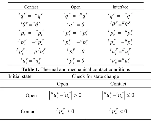
It is assumed that the domain Ωof the problem is divided into the sub-regions ΙΩand ΙΙΩ. Then, a common boundary is created between the adjacent sub-regions that consist of a number of node pairs; one node of each pair belongs to ΙΩ and the other to ΙΙΩ. The boundary between ΙΩ, ΙΙΩ expresses the existence of a crack or a material interface. The present analysis assumes that a number of node-pairs are able to come into contact or to open representing the crack and some nodes remain coincident expressing the interface between the adjacent sub-regions. These situations are treated using appropriate constraint equations on the common boundary for every time instant F as provided in Table 1. The superscripts I, II refer to the sub-region, the subscripts n, τ denote the normal or tangential component of the displacement and traction with respect to the local coordinate system; μ is the coefficient of friction and R is the thermal resistance along the contacting crack faces that is dependent on the normal contact traction pn.
1 1 11
]{
}
[
]{
}
[
)
(
F f f f F f f F T F II I, o II c II F c n, I c II i II II o I c I i I I T F II I, o II c II i II II o I c I I Iθ
Q
q
Θ
q
Θ
0
Q
p
R
Θ
Θ
Θ
0
0
Θ
Θ
Θ
0
Θ
θ
Q
0
Q
Q
Q
0
0
Q
Q
Q
0
Q
(7)where the vectors
I,IIθF ,
I,IIqF
are defined as:
F
o I F o I F c I F i I F II F I F II I, F o II F o I F c I F i I F II F I F II I,
q
q
q
q
q
q
q
θ
θ
θ
θ
θ
θ
θ
(8)and for the elastic part of the problem:
F f f f F f f F T F II I, o II c , II c n, II i II II o I c , I c n, I i I I T F II I, o II c , II c n, II i II II o I c n, I c , I i I Iθ
Q
q
Θ
p
U
0
U
μ
U
U
U
0
0
U
U
μ
U
U
0
U
u
P
0
P
P
0
P
P
0
0
P
0
P
P
P
0
P
1 11
]{
}
[
]{
}
[
)
(
(9)where the vectors
I,IIuF ,
I,IIpF
are defined as:
F
The subscripts o, c, i denote the open, contact state or the interface, respectively. Table 2 gives the criteria that are used during the procedure to check if the nodes of a pair come into contact or open and vice versa.
If the contact state of a node pair has been altered then the thermo-mechanical conditions along the crack faces should be updated according to Table 1. This fact in conjunction with the existence of the contact pressure-dependent thermal resistance R demands repeated solution of equations (7), (9) for the current time step. This iterative procedure stops when there is no change in the contact state and the criterion for the thermal resistance is fulfilled:
001
0
100
.
R
R
R
last prev
last
(11)
where Rlast and Rprev are the thermal resistances computed at the last and the previous iteration,
respectively. Then, analysis proceeds to the next time step.
Table 1. Thermal and mechanical contact conditions
Initial state Check for state change
Open Contact
Open F 0
n I F n
IIu u F 0
n I F n
IIu u
Contact F 0
n
Ip F 0
n
Ip
Table 2. Check of the contact state
2.1 Computation of fracture magnitudes
The displacement and stress fields behave in an oscillatory manner as the crack tip is approached, bounded by r ½ and r -½ respectively. Chen and Huang (1992) examined the case of
an interfacial crack under thermal loading conditions and proved that the singularity of heat flux
and temperature near the crack tip is also of the r ½ and r - ½ respectively but without the
oscillatory character observed in the stress and displacement fields. Therefore, quarter-point elements (QPEs) are used for the representation of temperature and displacement field while traction singular quarter-point elements (Katsareas and Anifantis 1996) are utilized to account for the heat flux and traction field near the crack tip. In order to analyze the interfacial fracture, the strain energy release rate (SERR) is employed.
Contact Open Interface
F II F
Iq q IqF IIqF IqF IIqF
F II F
Iθ θ IqF 0 IθFIIθF
F II F
Ip p
IpF IIpF IpF IIpF
F n II F n
Ip p F
n II F n
Ip p F
n II F n
Ip p
F n I F
Ip μ p
IpF 0 IuFIIuF
F n II F n
Iu u pF 0
n
I F
n II F n
The SERR G is related to the magnitude of complex stress intensity factor K0 according to
the equation:
S S
C C
K G
11 4
) ( 2
0 (12)
where νd, μd, represent the Poisson’s ratio and shear modulus, respectively and the
subscript d denotes the coating C orthe substrate S. The magnitude of K0 is computed via the
traction formula of Gao and Tan (1992):
2 / 2 A 2 A n
0 p p
πε
cosh
π
2
K [( ) ( ) ]1
)
(
(13)
In equation (13) A n
p and A
p refer to the normal and tangential component of traction at the crack tip A and
is the length of the crack tip element. The quantities ζ, ε are defined as ζ = (μC +κCμS)/ (μS +κSμC) and ε = 0.5πlnζ with κd = 3 - 4νd for plane strain or κd = (3 - νd)/ (1+νd)for plane stress. The traction formula is very simple since it demands only the calculation of traction components at the crack tip and it is preferred in the present analysis against alternative displacement formulas because it is not sensitive to the length of the QPE; therefore; it ensures accurate calculations with relatively coarse mesh (Katsareas and Anifantis 1996).
3. Computational results
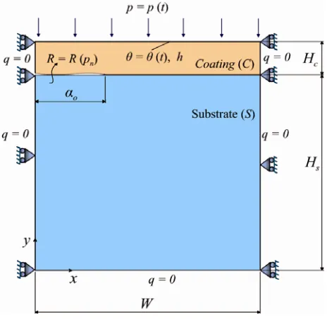
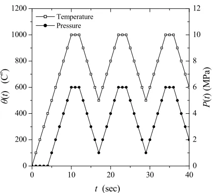
The problem under consideration is an interfacial crack extension in a TBC. Figure 1 depicts the geometry and the boundary conditions of the problem. It is a simple case of a coating–substrate bond. The upper surface of the coating is subjected to thermal or thermo-mechanical cyclic load which varies with time as shown in Fig. 2.
This temperature profile is very common in turbine blades where the components withstand very high heating and cooling rates. The thermal cyclic load may be combined by mechanical loading emanating from the pressure of hot gases
The fracture behavior of TBCs under thermal shock has been investigated in a previous work (Keppas et al. 2008) and the procedure was validated through comparison with solutions available in the literature. The bimaterial contains an edge crack of initial length αo = 0.05W.
The ratios of dimensions are Hs /Hc = 10 and W/Hs = 1.25. The crack is extended up to the
length αf = 0.1W utilizing five equal crack increments of length Δα = 0.01W. The procedure for
the determination of temperatures and displacements described in paragraph 2.1 is applied for the initial crack αo under the action of the cyclic load of Fig. 2. When SERR is calculated, the
boundary element model is updated in order to simulate a crack of length αo + Δα. The cyclic
load is imposed again leading to the calculation of the new SERR. The numerical procedure is repeated adding each time a crack increment Δα up to the final length αf. The time step is Δt = 1
sec and the length of QPE is
= α / 20, where α is the current length of the crack. The presence of pressure load on the top leads to crack closure, therefore the heat flux between the crack faces is controlled by the thermal contact resistance. It is supposed that the thermal resistance depends on the normal traction pn along the contacting crack faces with relations of the form:) exp(10 0.0002
) (
) exp(10 0.001
) (
8 -2
2
-8 1
1
n n
n n
p p
R R
p p
R R
(14)
The relation of the tractions on the contact region is controlled by the Coulomb’s friction law (Table 1). All the material properties are constant and throughout the temperature range. Though it is not the real case, it serves the purpose of the present approximation of interfacial crack growth under thermal cycling. The coefficient of heat convection is taken h = 50 W/m2 oC. The non-dimensional stain energy release rate and the time are derived via the expressions:
S C
C *
H E
G
G 2 2
) (
, 2
S C C
C *
H C
t k t
(15)
with Δθ being the difference Δθ = θmax – θmin, namelythe range of temperature load beyond
0 10 20 30 40 0
200 400 600 800 1000 1200
0 2 4 6 8 10 12
Temperature Pressure
P
(
t
) (M
Pa
)
θ
(
t
) (C
o )
t (sec)
Fig. 2. Thermo-mechanical cyclic load acting on the coating’s surface
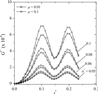
The first analysis regards pure thermal loading with the temperature profile of Fig. 2. The number of cycles required for the system to reach its steady cyclic response is not known a priori and should be detected with simulation of consecutive cycles. The analysis indicated that two consecutive cycles are sufficient for the computation of the representative range of G*.
Beyond the 2nd cycle the response does not change. The transient behavior of G* is plotted in
Fig. 3 for several non-dimensional crack lengths α* = α/W where αis the current crack length.
These results correspond to the thermal resistance function R1 (equation 14) and SERR is
calculated for the almost frictionless case μ = 0.01 and the more realistic μ = 0.1. Low values of coefficient of friction are valid in cases of repeated cyclic loading due to the polishing of the crack surfaces caused by the sliding contact. However, for pure thermal loading G* is not
sensitive to the coefficient of friction.
Figure 4 presents results with regard to the combined thermo-mechanical loading of Fig. 2 assuming thermal resistance R1. Again, two consecutive cycles are adequate to account for the
transient effect up to the steady cyclic response. In the presence of pressure load in phase with the applied temperature the impact of friction on the SERR is significant. SERR is drastically reduced because of the restriction of sliding due to the pressure. The decrease of the peak value of G* is totally responsible for the reduction of the range of SERR. This remark is valid for all the crack lengths and explained by the fact that the maximum pressure acts simultaneously with the maximum temperature. Comparing the results of Fig. 3 and 4 one can see that the peak value of G* is higher for the pure thermal cycling and takes lower values for the combined
0.0 0.1 0.2 0.3 0
2 4 6 8 10
α*
= 0.05 0.06 0.08 0.1
G
* (x 1
0
-6 )
t*
= 0.01
= 0.1
Fig. 3. SERR variation for pure thermal cycling withthermal resistance R1
0.0 0.1 0.2 0.3
0 2 4 6 8 10
0.1 0.08 0.06
α*
= 0.05 = 0.01
= 0.1
G
* (x 1
0
-6 )
t*
Fig. 4. SERR variation for thermo-mechanical cycling with thermal resistance R1
The characteristic ranges *
max *
max
* G G
G
for a number of crack lengths can be further
utilized in Paris type laws of the form d
dN f
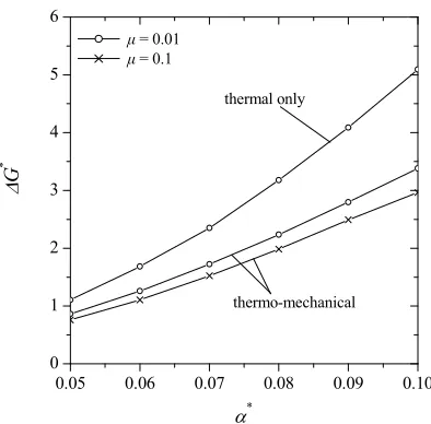
G* to extract the fatigue life of thestructure in terms of load cycles. Figures 5 and 6 present the evolution of ΔG*during the crack
0.05 0.06 0.07 0.08 0.09 0.10 0
1 2 3 4 5 6
μ = 0.01 μ = 0.1
thermal only
thermo-mechanical
*
G
*
Fig. 5. Effect of coefficient of friction on the range of SERR for thermal resistance R1
The Fig. 5 depicts the range of SERR for a growing crack when the thermal resistance is
R1. Apparently, when the loads is thermo-mechanical the range is reduced up to 45% comparing
to the pure thermal loading which produce very similar ΔG*. This difference is more
pronounced as the crack is extended. Another remark is that the higher the crack length is, the higher the ΔG*. This comes in agreement with the numerical data of Nusier and Newaz (2000)
and it is also apparent in Fig. 6. The last figure provides the influence of the level of thermal resistance on the predicted ΔG*. The lower thermal resistance R
2 permits the restriction of the
temperature jump across the crack faces and subsequently reduces ΔG* up to one order of
magnitude. This remark is very important should be taken into account when assessing the fatigue life and crack severity in bimaterials.
0.05 0.06 0.07 0.08 0.09 0.10 0
1 2 3 4 5 6
thermal
thermo-mechanical, μ = 0.1
R2 R1
G
*
*
4. Conclusions
The transient nature of the load requires a number of consecutive load cycles to be simulated in order to estimate the steady response of the system. When the procedure is applied to interfacial crack growth an iterative procedure is necessary in order to take into account the effect of crack closure on the thermal field around the crack tip. Even a low coefficient of fiction is able to influence significantly the predicted range of strain energy release rate when a pressure load acts in phase with the temperature. The assumption for the level of the thermal resistance is of high importance for the fatigue life prediction and the assumptions for thermal insulation or perfect thermal contact along the crack faces may lead to conservative or optimistic results.
Извод
Предвиђање помоћу граничних елемената слома отпора термалне
заштитне превлаке ( ТЗП) изложене термо-механичким оптерећењима
L.K. Keppas1, N.K.Anifantis2*
1Mechanical and Aeronautics Engineering Dept., University of Patras, Greece, GR-26500
2Mechanical and Aeronautics Engineering Dept., University of Patras, Greece, GR-26500
*Corresponding author
Резиме
Ова студија описује под-доменски поступак помоћу граничних елемената за термалну заштитнупревлакусапрслиномизложенуцикличнимтермо-механичкимоптерећењима. Коришћене су неспрегнуте квази-статичке једначине термоеластичности на основу граничних интеграла да би се узео у обзир прелазни карактер термичког оптерећења. Прслинајепостављенадуждодирнихповршинаизмеђуметалскогподслојаикерамичке превлаке. Затварање прслине се догађа на рачун термичке дисторзије и притиска који делујенаповршинупревлаке. Прематоме, натоплотнифлуксизмеђуповршинапрслине утиче ниво затварања прслине, па тачно одређивање температура и померања захтева итеративно решавање термичког и механичког дела проблема. Резултати показују да параметри као што су коефицијент трења и отпор термичког контакта имају значајан утицајнакапацитетпредвиђеногсломаконструкцијасапрслиномиморајубитиузетиу обзирприпроценивекатрајањауследзамора.
Кључне речи: Превлачење за термалну заштиту, слом отпора заштите, гранични елементи, цикличнотермо-механичкооптерећивање, међуповршинскапрслина
References
Banerjee PK (1994). The boundary element methods in Engineering, McGraw-Hill.
Brebbia CA, Telles JCF, Wrobel LC (1984). Boundary Element Techniques: Theory and
Chen WH, Huang CC (1992). On the singularity of temperature gradient near an inclined crack terminating at bimaterial interface, International Journal of Fracture, 58, 319-24.
Chen X, Hutchinson JW, He MY, Evans AG (2003). On the propagation and coalescence of delamination cracks in compressed coatings: with application to thermal barrier systems,
Acta Materialia, 51, 2017-2030.
Gao YL, Tan CL (1992). Determination of characterizing parameters for bimaterial interface cracks using the boundary element method, Engineering Fracture Mechanics, 41, 779-784. Hattiangadi A, Siegmund T (2005). An analysis of the delamination of an environmental
protection coating under cyclic heat loads, European Journal of Mechanics, A/Solids, 24, 361-370.
Katsareas DE, Anifantis NK (1996). Performance of quarter-point boundary elements in analyzing thermally stressed kinked and curved cracks, Computer Methods in applied Mechanics and Engineering, 137, 153-165.
Keppas LK, Giannopoulos GI, Anifantis NK (2008), Transient coupled thermoelastic contact problems incorporating thermal resistance: A BEM approach, CMES: Computer Modelling in Engineering and Science, 25, 198-209.
Nusier SQ, Newaz GM (2000). Growth of interfacial cracks in a TBC/superalloy system due to oxide volume induced internal pressure and thermal loading, International Journal of Solids and Strucutres, 37, 2151-2166.
Prasad NNV, Aliabadi MH, Rooke DP (1996). Thermomechanical fatigue crack growth,
International Journal of Fatigue, 18, 349-361.
Rangaraj S, Kokini K (2003). Interface thermal fracture in functionally graded zirconia– mullite–bond coat alloy thermal barrier coatings, Acta Materialia, 51, 251-267.