Volume-5 Issue-2
International Journal of Intellectual Advancements
and Research in Engineering Computations
Efficiency improvement in refrigeration system using sub-cooler
Mrs.A.D.Latha 1, R. Kavinkumar2, A.Meezan2, R.Naveenkumar2, B. Raghuram2, 1
Associate Professor, 2UG Students,
Department of Mechanical Engineering, Nandha Engineering College, Erode-52, Tamil Nadu, India.
[email protected], [email protected],
Abstract:-This work investigates the thermal performance of a thermal battery used in the domestic refrigerator as a sub cooler. A Thermal Energy battery is physical structure used for the purpose of storing and releasing thermal energy. In order to run the compressor without cut-off, the charging mode is used. In the charging mode, refrigeration effect is stored in the thermal battery. In the discharging mode, the refrigeration effect is used to sub cool the refrigerant after the condensation. This study also examines the thermal performance of the sub-cooled ice storage air conditioner under different cooling loads. In the ordinary refrigerator, when the required temperature is attained, the compressor is cut-off and vice versa. During the starting of the compressor the torque needed is high, so the power consumption is high. By using this thermal battery, the compressor need nor to be cut-off and hence the power consumption is also reduced. The system will give more cooling capacity and higher COP by the contribution of the thermal battery used as a sub cooler.
Keywords:efficiency, compressor, condensation, evaporation, sub-cooler, COP.
I.INTRODUCTION
Refrigeration is the process of moving heat from one location to another in controlled conditions. The work of heat transport is traditionally driven by mechanical work, but can also be driven by heat, magnetism, electricity, laser, or other means. Refrigeration is a science of producing and maintaining heat below that of the surrounding temperature. It means that the heated substance is to be cooled. The heat always flows from the higher temperature to lower temperature. Heat is the major
problem which is to be reduced in all the places. The refrigeration unit is to be employed in such places.
The equipment used to maintain the system at the lower temperature is known as refrigeration system.
II.LITERATURE REVIEW
Ming-Chao Huang et al (2006) dealt with the theoretical and experimental investigations of the thermal performance of a thermal battery used in the ice storage air-conditioning system as a sub cooler. The thermal battery utilizes the superior heat transfer properties of two-phase closed thermosiphon and eliminates the drawbacks found in convectional energy storage systems. Experimental investigations are first conducted to study the thermal behaviour of thermal battery under different charge temperatures (-5 °C to -9 °C) in which water is used as the energy storage material. This study also examines the thermal performance of the sub-cooled ice storage air
conditioner under different cooling loads.
Experimental data of temperature variation of water, ice fraction, refrigerant mass flow rate and COP are obtained. The results show that super cooling phenomenon appears in the water and it can be ended when the charge temperature is lower than -6°C.
The system gives 28% more cooling capacity and 8% higher COP by the contribution of the thermal battery used as a sub-cooler. Bilal Ahmed Qureshi (2013) deals that the thermo economic considerations are given to heat exchanger inventory allocation in the vapour compression cycles with mechanical sub cooling. Investigation is made with respect to constant work rate, heat rejection and cooling rates as well as heat transfer in the sub cooler. It was found that no minimum exist for any of
the cost functions with respect to the absolute temperature ratio and the average sub cooling absolute temperature ratio. The derivatives for the integrated sub cooling cycle can be generated from the derivatives of the dedicated sub cooling cycle. It was concluded that the cost optimization of the integrated mechanical sub cooling system is qualitatively the same as the dedicated sub cooling system.
Liang Yang (2010) deals with the energy saving opportunity of supermarket refrigeration systems using sub cooler between the Medium-Temperature (MT) refrigeration system and the Low-Temperature (LT) refrigeration system has been identified in the previous work. The optimal sub cooling control is also discussed. With optimal sub cooler size and sub cooling control, the maximum energy savings of integrated two-temperature supermarket refrigeration system using R404A or R134a as working fluid can achieve 27% or 20%.
Chun-Lu Zhang et al (2015) presents a model-based analysis on the energy saving potential of supermarket HVAC (heating, ventilating, and air-conditioning) and refrigeration systems using multiple sub coolers among the high-temperature HVAC system, the medium-temperature refrigeration system, and the low temperature refrigeration system. The principle of energy reduction is to have the higher COP system generate more cooling capacity to increase the cooling capacity or reduce the power consumption of the lower COP system. The sub cooler could be placed between the medium-temperature and low-medium-temperature systems, between the high-temperature and medium temperature systems, and between the high-temperature and low-temperature systems. All integration scenarios of adding one, two and three sub coolers have been investigated. The optimal sequence of adding sub coolers is also proposed.
SUMMARY OF LITERATURE REVIEW:-
The information from the above journals shows the need of instalment of sub cooler in refrigeration system for increase in COP. In the ice storage air conditioning system, the double pipe is used in order to transfer heat. Instead we kept copper coils in close to transfer the heat.
III.WORK FLOW PROCESS:-
Refrigeration System:
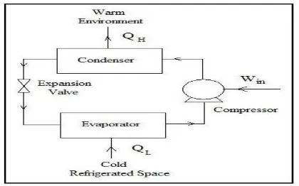
The vapour compression refrigeration
system is normally used in fridges. Vapour compression refrigeration system is having four
process namely compression, condensation,
expansion and evaporation.
p-h Diagram of VCRS
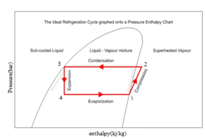
The following processes are involved in vapour compression refrigeration system. The sequence of the operation is mentioned in the figure 1.
(1-2)- Compression process (2-3)- Condensation process (3-4)- Expansion process (4-1)- Evaporation process
Figure 1 p-h diagram of VCRS without sub cooling
refrigerant used does not leave the system, but is
circulated throughout the system alternately
condensing and evaporating.
Figure 1(a) VCRS without sub cooling
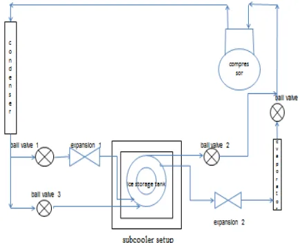
ADDITIONAL SET-UP OF SUB COOLER: The construction is that the copper tubes are wounded into the rectangular box with both sides of projected copper tubes. These both sides are the charging and discharging modes of the sub-cooler. The refrigerant flowing from the condenser is split into two ways using the T-Joint and the refrigerant flowing tube connected to the expansion valves and then to the respective charging and discharging modes. In the charging mode the refrigerant flowing tube is connected directly to the compressor without entering the sub-cooler set up. In the discharging mode the refrigerant flowing tube is connected to the evaporator after entering the sub-cooler set up. The copper tube which is present inside the rectangular box is closed at the both ends. It is filled with refrigerant. The rectangular box is filled with water. The normal refrigerant flow tubes are wounded over the projected copper tubes at both the ends. These wounded copper tubes are welded using gas welding with the projected copper tubes so that the heat transfer will occur more effectively. The rectangular box is closed at both the ends. The schematic diagram of sub-cooler fixed in refrigerator is shown in Figure.
IV.WORKING PRINCIPLE OF SUBCOOLER:
The coefficient of performance in
refrigeration is achieved by setting up the sub cooler. The sub cooler setup consists of evaporator, copper tube wounded inside the rectangular box. The
refrigerant used here is R134a. The sub cooler setup consists of charging and discharging modes.
p-h Diagram of VCRS with sub cooling
Sub cooling is the temperature of a liquid or solid below its saturation temperature. Figure 2 shows the sub cooling process (3’-4’). Due to the sub cooling the refrigeration effect is increased as shown in the p-h diagram.
Figure 2 p-h diagram of VCRS with Sub cooling
When the VCRS system is assisted with sub cooling process, the length of the condensation process will be extended and the evaporation process line also extended. Thus the refrigeration effect is increased with respect to constant work done which leads to increase in COP
.
cooling setup is fixed between the condenser and evaporator. In the charging mode, the refrigerant coming from the condenser flows through the sub cooler setup and then directly to the compressor whereas in the discharge mode the refrigerant coming from the condenser enters the sub cooler setup and then to the evaporator. The refrigerant which is flowing through the charging and discharging modes enters through the expansion valve. Thus the increase in cooling is achieved by using this kind of sub cooler
.
Figure 2(a) VCRS with Sub cooling
V.DESIGN CALCULATION Design description
Q1 =Input power (100 watts i.e. given in the compressor name plate) in kW
Q2 =Amount of heat rejected by the refrigerant when sub cooling in kW
Q3 =Amount of heat should be absorbed by the water to sub cool the refrigerant in kW
m =Mass flow rate of the refrigerant in kg/s h =Enthalpy in kJ/kg
T =Temperature of the refrigerant in ˚c t = Temperature of the water in ˚c mw = Mass flow rate of the water in kg/s Ʋ =Specific volume of water in m³/kg v =Volume flow rate in m³/s
V =Volume of the water filled in m³ d =Diameter of the copper tube in m
A =Heat transfer area of the copper tube in m² ho =Heat transfer coefficient of copper in W/m²K p =Pressure of the refrigerant in bar
s = Entropy of the refrigerant in kJ/kg K
Cr=specific heat of refrigerant in kJ/kg K Cw = specific heat of water in kJ/kg K
Sub cooling coil length calculation
The diameter of the copper tube = 12mm
Take heat transfer coefficient of copper as 450
W/m
2K
Q
1=h
0A(ΔT)kW
ΔT=subcooling temperature 7 ˚c, W.K.T
Q
1=100watts
Take length of copper tube = 1.5m
Q
1=450ᵡ3.14ᵡ12ᵡ10
-3ᵡ1.5ᵡ7=178.038watts
This is not desirable then Take L=1.2m
Q
1=450ᵡ3.14ᵡ12ᵡ10
-3ᵡ1.2ᵡ7=142.4304W
This is also not desirable
Take L = 1m
Q
1=450ᵡ3.14ᵡ12ᵡ10
-3ᵡ1.0ᵡ7
Q
1=118.692W , Nearly equals to 100 watts
So the length of copper tube as 1m for the
subcooler
VI.CONCLUSION AND FUTURE SCOPE This work provides a thermal battery allowing operation of charge, discharge and
simultaneous charge and discharge modes.
heaters, boilers and furnaces. The copper tube is filled with refrigerant which cools and evaporates according to the temperatures. In future this is to be replaced by series of straight copper tubes arranged parallel to transfer heat and as to perform thermosiphon effect. By doing so we can also be able to transfer more amount of heat that is there is more heat exchange takes place than the other. The sensors are used instead of manually opening and closing of charging and discharging modes.
References
[1] Institut international du froid organisation inter governement le pour le developement du froid 17th informatory note on refrigerating technologies how to improve energy efficiency in refrigerating equipment [2] International journal of refrigeration volume 27,issue 2,march 2004, pages 120–128 thermal performance of cold storage in thermal battery for air conditioning
[3] International journal of heat and mass transfer volume 41, issues4-5,February–march 1998, pages 769-783 a study of supercooling phenomenon and freezing probability of water inside horizontal cylinders
[4] International journal of scientific & engineering research, volume 6, issue 5, may-2015:issn 2229-5518increasing the efficiency of refrigerator by reduces the losses in evaporator, compressor and condenser.
[5] International journal of research in aeronautical and mechanical engineering to study the effect of sub-cooling and diffuser on the coefficient of performance of vapour compression refrigeration system
[6] volume 2, issue 2 (2014) 325-332 issn 2347 - 3258 international journal of advance research and innovation 325 IJARI thermodynamic performance evaluation of multi-evaporators single compressor and single expansion valve and liquid vapour heat exchanger in vapour compression refrigeration systems using thirteen eco friendly refrigerants for reducing global warming and ozo ne depletion
[7] Issue 3, vol.1 ( january 2013) issn 2249-6149 page 521 effect of sub cooling and superheating on vapour compression refrigeration systems using r-22 alternative refrigerants
[8] International advanced research journal in science, engineering and technology vol. 2, issue 6, june 2015 enhancement of coefficient of performance by analysis of flow through vapour compression refrigeration cycle using cfd
[9] elk asia pacific journals – special issue isbn: 978-81-930411-4-7 effect of subcooling in vcrs as compared to simple vcrs system
[10] International journal of engineering research & technology (ijert) issn: 2278-0181enhancement of cop in vapour compression refrigeration system
[11] Effect of condenser subcooling of the performance of vapor compression systems: experimental and numerical investigation
[12] International journal of engineering research and advanced technology (ijerat) issn: 2454-6135 [volume. 02
issue.05, may2016] "cop enhancement of domestic refrigerator by sub cooling