Agilent Technologies
Voice Quality in Converging
Telephony and IP Networks
By Stefan Pracht,
Agilent Technologies
XoIP Product Marketing Manager
Dennis Hardman,
Agilent Technologies
XoIP Learning Products Engineer
2
Contents
Introduction ...
page 3Why Is Voice Quality Again An Issue? ...
page 3Voice Quality Is Subjective ...
page 4Voice Quality Defined ...
page 4Clarity ...
page 6Packet Loss ...
page 7Speech codecs ...
page 8Other Factors Affecting Clarity ...
page 8End-to-End Delay ...
page 9PSTN Delay ...
page 9IP Network Delay ...
page 9VoIP Device Delay ...
page 9How Much Delay is Too Much? ...
page 10Echo ...
page 11What Causes Echo? ...
page 11What Makes Echo Perceptible? ...
page 12How Do Networks Deal With Echo? ...
page 12Silence Suppression and Comfort Noise Generation ...
page 13Testing Voice Quality ...
page 14Measuring Clarity ...
page 14Measuring Delay ...
page 15 Acoustic PING ... page 15 MLS Normalized Cross Correlation ... page 15Measuring Echo ...
page 15 Echo Characterization ... page 15Echo Cancellers ...
page 15Perceived Annoyance Caused by Echo (PACE) ...
page 16Measuring VADs ...
page 16Agilent Technologies Voice Quality Test Solutions ...
page 17About the Authors ...
page 18Stefan Pracht ...
page 18Dennis Hardman ...
page 183
Introduction
As the telephone industry changesthat is, as new technologies and servicesare added, existing technologies are applied in different ways, and new players become involvedmaintaining the basic quality of a telephone call becomes increasingly complex. Although voice quality has evolved over the years to be consistently high and predictable, it is now an important differentiating factor for new voice-over-packet networks and equipment. Consequently, measuring voice quality in a relatively inexpensive, reliable, and objective way becomes very important.
Voice quality means different things, depending on your perspective. On one hand, it is a way of describing and evaluating speech fidelity, intelligibility, and the characteristics of the analog voice signal itself. On the other hand, it can describe the performance of the underlying transport mechanisms. This paper discusses voice quality influencing factors, and network impairments and their causes in a converged telephony and IP network, all from the perspective of the quality of the analog voice signal. Network performance issues will be discussed where appropriate, but the topic of voice-over-packet (VoP) performance with regards to packet delivery is not covered in any real depth. Voice quality testing concepts, methods, and tools will also be discussed.
Why Is Voice Quality Again An Issue?
Traditional public switched telephone networks (PSTN) have long since addressed the voice quality problem by optimizing their circuits for the dynamic range of the human voice and the rhythms of human conversation. PSTNs have evolved to provide an optimal service for time-sensitive voice applications that require low delay, low jitter, and constant but low bandwidth. While these networks do not produce perfect quality, users have become accustomed to PSTN levels of voice quality, and comparisons are often made in this context. That is, PSTN voice quality is relatively standard and predictable.
IP networks, though, were built to support non-real-time applications, such as file transfers or e-mail. These applications are characterized by their bursty traffic and sometimes high bandwidth demand, but are not sensitive to delay or delay variation.
If PSTNs and IP networks are to converge, IP networks (and the convergent points) must be enhanced with mechanisms that ensure the quality of service (QoS) required to carry voice. This point is especially important considering that users of traditional telephone networks are used to quite high voice quality standards. Providing comparable service quality in IP networks will drive the initial acceptance and success of packet services, such as voice-over-IP.
Voice-over-packet technologies, particularly VoIP, have made maintaining voice quality more complex by adding non-linear compression and the need for timely packet delivery to networks not originally set up for these conditions. Transmission conditions that pose little threat to non-real-time data traffic can introduce severe problems to real-time packetized voice traffic. These conditions are:
Real-time Bandwidthmany data networks are not designed for the real-time bandwidth requirements of speech. Data networks typically have not needed to rely on streams of packets arriving at their destinations within narrow time windows (in other words, with relatively non-varying delay). As voice signals are introduced into these networks, methods are employed to ensure this real-time transport, but voice quality can still suffer if these methods do not work properly. Although real-time speech has a reasonably low bandwidth requirement, it needs either a constant available bandwidth (for linear codecs) or direct available bandwidth (for low bit rate codecs). Another related condition has to do with bandwidth capacity in general. While many service providers have adequate capacity to handle the real-time voice traffic on their data networks without compromising other non-voice traffic, linear and non-linear voice compression techniques are still being used, particularly when voice is transmitted to the desktop. Non-linear compression can be a major cause of reduced voice quality.
4
Important Gateway ProcessesVoP networks rely on network processes (often built in to gateways) that help some voice quality problems. For example, silence suppression is used to prevent packets from being created and transmitted during the quiet periods between spoken phrases. Also, echo cancellers are needed to eliminate echo that becomes perceptible when delay is introduced. If these kinds of processes do not work properly, voice quality suffers.
Packet Losspacket network applications compensate for packet loss by retransmitting lost packets through the use of TCP. Data applications such as file transfers and email are less sensitive to the time it takes for this to occur, but real-time voice traffic cannot tolerate this delay. In addition, VoIP networks use connectionless transfer protocols such as UDP that do not guarantee delivery at all. Lost packets mean lost voice information.
Delaythe time it takes for a voice signal to be digitized, packetized, transmitted, routed, and buffered contributes to the delay experienced by a user. This delay can interfere with normal conversations and can exacerbate existing problems on the network such as echo.
Non-Linear Codecsas alluded to above, an important reason to measure voice quality is the continued development and use of non-linear perceptual codecs. Non-linear perceptual codecs compress voice such that the
perceptually important information is preserved, but not necessarily the voice waveform. Said another way, these codecs preserve how the voice sounds
without preserving all of the frequency spectrum information. This non-linear compression renders many traditional speech measurements less useful; thus, the need for new measurement techniques emerges.
Voice Quality Is Subjective
Generally speaking, voice quality can be expressed (and therefore measured) primarily with respect to the talker and the listener who experience it. Voice quality should be approached from an end-to-end perspective; that is, regardless of the systems, devices, and transmission methods used, any voice quality metric should be expressed in the context of the users experience. But the end-to-end aspect of voice quality is accompanied by the inherent
subjective nature of this type of qualitative evaluation. What a listener considers high quality (or, for that matter, low quality) is influenced by expectations, context/environment, physiology, and mood.
These end-to-end and subjective characteristics of voice quality make
measuring it an interesting challenge. Testing methods and equipment must be able to address these issues directly, as well as provide data about the reasons for specific voice quality measurement results.
Voice Quality Defined
At this point, voice quality must be clearly defined before any discussion of its characteristics and components can proceed. Many factors influence ones perception of the quality of a telephone call, ranging from the ease or difficulty in placing the call to the quality of the sound in the earpiece. At a very high level, basic telephone call quality is made up of three fundamental components: Service Quality
Sound Quality Conversation Quality
5 Service Quality Offered services— like,Calling card, 1-800/900 services, follow-me, voicemail Availability of users Echo in other countries or regions
Sound Quality
Network Availability— down time, busy signals Reliability; such as dropped calls or wrong number End-to-end delay Silence
Conversation Quality
Price—Loudness Distortion Noise Fading Cross talk Loudness Distortion Noise Fading Cross talk suppression performance Echo canceller performance
Table 1 provides more detail.
Table 1: Details of service quality, sound quality, and conversation quality.
The components in Table 1 impact perceived quality whether the telephone call occurs over traditional PSTN lines, emerging VoIP networks, or a hybrid of both, and they are often dependent on each other when it comes to a users ultimate judgement of the quality of a given telephone call. For example, questionable sound quality is frequently tolerated, ignored, or not noticed when service quality is very high. Users of cell phones or over-seas satellite links tolerate or ignore sound quality problems because of the usefulness of the call itself. Another example involves conversation quality. When a perceptible time lag between phrases spoken by talker and listener exists, many users perceive such a time lag as a sound quality or service quality problem.
Many aspects of service quality are closely tied to service provider business issues and network provisioning decisions, and less closely tied to the technical aspects of network performance and network device operation. Yet, sound quality and conversation quality seem to be closely related and quite dependent on the details of network deployment and performance. For this reason, voice quality is defined as the qualitative and quantitative measure of the sound and conversation quality of a telephone call.
Given the previous definition of voice quality, three elements (shown in Figure 1) emerge as the primary factors affecting voice quality, particularly in the case of networks using voice-over-packet or voice-over-IP technologies.
Claritya voice signals fidelity, clearness, lack of distortion, and intelligibility.
End-to-End Delaythe time it takes a voice signal to travel from talker to listener.
6
Figure 1: Relationship among Clarity, Delay, and Echo with regards to Voice Quality.
The relationships among clarity, delay, and echo can be quite complex as shown in the three-dimensional Figure 1. If you think of voice quality as a single plotted point in the graph, you can see that voice quality improves as the point is plotted closer to the intersection of the three lines. In other words, as the distance between the voice quality point and the intersection increases, voice quality decreases. Other interesting observations include:
Perception of One Aspect Affects Perception of Overall Voice Quality
One of the main reasons clarity, delay, and echo are grouped together is that many users will report unacceptable voice quality if only one aspect of voice quality is unacceptable. For example, users rarely distinguish between distortion and annoying echo; they simply report unacceptable call quality. While network equipment manufacturers and service providers often need to distill voice quality issues into distinct areas, users do not.
Clarity and Delay are Orthogonal Aspects of Voice Quality
Distortion and fidelity are independent of end-to-end delay in that a voice signal can experience significant delay, yet sound very good. The converse is also true: A voice signal can sound very distorted but travel end-to-end too quickly to be perceived by the user. For voice quality to be perceived as acceptable, however, clarity must be reasonably good and delay must be reasonably short.
Echo is Dependent on Delay and Echo Affects Clarity
As this paper details later on, echo is perceptible only when network delay (defined in this case as the round-trip delay from the talker to the point of echo) is above a certain threshold. In other words, echo coming from any remote point in the network will not be heard unless it is delayed long enough to be audibly separate from the original spoken phrase. Similarly, perceived clarity is often negatively impacted by audible echo even though the level of distortion in the echo signal itself may be quite low.
Decreasing Clarity
Increasing
Delay
Increasing Echo
“Speech Quality
Space”
7
Important Note: Figure 1 provides a conceptual model only. It is true that voice quality is influenced by clarity, delay, and echo, and that the relationships between them are generally shown by the graph. However, no known
mathematical relationship exists that can be used to derive a single voice quality number, or a vector whose length uniquely quantifies voice quality. Any
representation of voice quality, whether it is for individual devices or voice-over-packet (VoP) systems, must include at least a clarity and a delay component, and optionally an echo component.
Breaking voice quality into three distinct areas such as clarity, delay, and echo make evaluating voice quality a manageable process. While there are many aspects of VoP telephony that can be measuredand some will be discussed later in this paperclarity, delay, and to a lesser degree, echo form the basis of most voice quality concepts and test techniques. These three components of voice quality and other related topics are discussed next.
In the context of voice quality testing, clarity describes the perceptual fidelity, the clearness, and the non-distorted nature of a particular voice signal. Clarity can also be described as speech intelligibility, indicating how much information can be extracted from a conversation. However, it is possible to understand what is said during a voice conversation, but still experience poor clarity. For example, the voice can be distorted and not easily heard, but still be understood. The subtle, yet important, distinction between clarity and intelligibility
illustrates just one part of the complexity involved when attempting to quantify voice quality. Clarity, and a persons evaluation of it, depends on numerous factors. For example, certain frequency bands are more important for perceived clarity than others. Human listeners are more likely to find that distortion or attenuation in the 1,000- to 1,200-Hz band decreases clarity and intelligibility more than distortion or attenuation in the 250- to 800-Hz band. Another example is that complete sentences are usually much better understood due to the logical word flow in a sentence (and therefore,
perceived as having higher clarity) than a sequence of unrelated words, even if the random word sequence is less distorted.
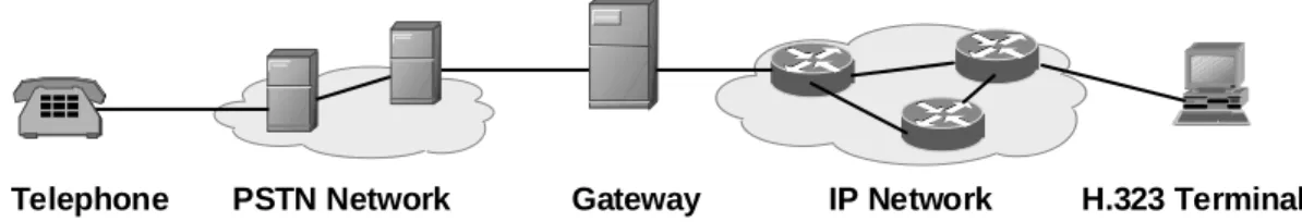
What are the influencing factors for clarity in a combined IP/PSTN telephony network? Figure 2 shows a typical implementation.
Clarity
The PSTN telephone influences clarity through the quality of its loudspeaker and microphone, the loudness of the transmitted and received signal, and the acoustic echo generated between the loudspeaker and microphone.
The PSTN network uses digital voice transmission for greater efficiency in the backbone. Digitizing analog voice signals often affects voice clarity.
The VoIP Gateway interconnects the PSTN with the IP network using voice and signaling schemes. Gateway components affecting clarity are the speech codec, silence suppression mechanism, and comfort noise generator.
The IP network, even without active voice components, affects clarity through its tendency to lose packets and to add extensive jitter to voice packet delivery. The H.323 terminal (like, an application on a PC or an IP telephone) also affects
the clarity through its speech codec, silence suppression mechanism, and microphone and loudspeaker quality.
Each of these network components have an impact on voice clarity:
Figure 2: Example of a combined PSTN/VoIP network.
Gateway IP Network
PSTN Network H.323 Terminal
8 The following sections examine a few of the more important factors affecting voice clarity.
Packet Loss
Packet loss is not uncommon in IP networks. As the network, or even some of its links, becomes congested, router buffers fill and start to drop packets. Another cause can be route changes due to inoperative network links. An effect similar to packet loss occurs when a packet experiences a large delay in the network and arrives too late to be used in reconstructing the voice signal. For non-real-time applications, such as file transfers, packet loss is not critical. Packet protocols provide retransmission to recover dropped packets. However, in the case of real-time voice information, packets have to arrive within a relatively narrow time window to be useful to reconstruct the voice signal. Retransmissions in the voice case would add extensive delay to the reconstruction and would cause clipping or unintelligible speech.
To avoid packet loss for real-time applications, mechanisms are required in the IP network to assure minimum throughput for selected applications. These mechanisms minimize packet loss and delay for higher priority traffic, such as voice. Various router mechanisms can be used to meet this objective. These include prioritization schemes, such as Weighted Fair Queuing (WFQ), and router flow control mechanisms, such as the Internet Engineering Task Forces (IETF) Multi-Protocol Label Switching (MPLS) tagging scheme or the use of Type of Service (TOS) bits in the IP header. To use these mechanisms, a network administrator must decide what priority and resources to provide for each specific service class and configure the network accordingly. A more dynamic alternative for assigning resources is the Resource Reservation Protocol (RSVP), which permits a terminal or voice gateway to request a specific IP quality of service.
Regardless of which is used, a deeper problem remains. Quality of Service (QoS) is defined on an end-to-end basis, and therefore requires that sufficient network resources be provided throughout the network path. This is not an overwhelming issue for an enterprise network or a single ISP environment where all resources can be administered through one network manager. However, it is almost impossible to administer when multiple ISPs or service providers are involved, as is the case in virtually every national or international long distance call. In addition, this fulfillment of QoS assumes that all routers in the network are equally capable of identifying voice traffic and providing the required network resources. This is still the exception rather than the rule in todays IP networks because standards for many of these mechanisms have not been finalized and implemented by equipment manufacturers.
Speech Codecs
A speech codec transforms analog voice into digital bit streams, and vice versa. In addition, some speech codecs also use compression techniques, removing redundant or less important information to reduce the amount of transmission bandwidth required. Said another way, many codecs compress voice signals by preserving only those parts of the voice signal that are perceptually important. In the context of voice quality testing, the phrase perceptually important refers to those parts of the audio signal that have the largest impact on a humans perception of the signal particularly if those parts are distorted or omitted. Perceptual importance is determined via an understanding of human physiology and cognitive psychology. Consequently, and depending on the type of codec used, the actual voice waveform may not be reproduced at the receiving end of a VoP conversation. Codecs such as G.711 can be thought of as linear because they come very close to reproducing the waveform. However, low bit rate codecs such as G.729 and G.723.1 try to reproduce the subjective sound of the signal rather than the shape of the speech waveform and are therefore generally thought of as non-linear.
9
End-to-End Delay
Essentially, compression is a balancing act between voice quality, local computation power, and the delay and network bandwidth required. The greater the bandwidth reduction, the higher the computational cost of the codec for a given level of perceived clarity. In addition, greater bandwidth savings generally cause higher computational delay and therefore significantly increase the end-to-end delay. The network planner must make an informed tradeoff between bandwidth, voice quality, and delay.
A codecs affect on voice quality is also influenced by packet size, packet loss, and any error-correction mechanisms utilized by the codec itself.
Other Factors Affecting Clarity
Other factors affect voice clarity. Some are the kinds of things you would expect in any audio or digital transmission channel, and others are specific to voice-over-packet networks. Briefly, these are:
Noiseall noise, regardless of its source, has the potential to reduce the clarity of a voice signal. Noise can originate from analog lines or from bit errors on data transmission lines. If it is introduced prior to the voice signal being digitized, it will be faithfully reproduced by the codec if possible. Noise introduced after a voice signal has been converted back to analog will further distort the voice signal.
Voice Activity Detectorsdiscussed in more detail later, voice activity detectors (VADs) can introduce clarity degradations by inadvertently removing (clipping) parts of speech utterances.
Echospeech that is echoed back to the speaker such that it is perceived during conversations can have a significant (albeit indirect) effect on perceived clarity. For example, if you can hear your own voice echoed back to you as you are talking, this can be annoying and perhaps disruptive.
External Environmental Factorsit is possible to have excellent audio quality on a telephone speaker, but due to room noise, user mood, end-user expectations, and other intangible factors, the audio quality could still be perceived as unacceptable. This affects testing methods and makes true subjective testing with human subjects more difficult.
Delay is the time required for a signal to traverse the network. In a telephony context, end-to-end delay is the time required for a signal generated at the talkers mouth to reach the listeners ear. End-to-end delay is the sum of the delays at the different network devices and across the network links through which voice traffic passes. Many factors contribute to end-to-end delay, which are covered next.
PSTN Delay
Public switched telephone network (PSTN) delay occurs most often due to the transmission delay on long-distance trunks. The delay is especially high when satellite links are involved (a geostationary satellite link has a transmission delay of about 250 milliseconds). In addition, switching delay in network nodes is relatively small when compared to transmission delay. In the vast majority of cases, PSTNs exhibit relatively low delay, which is primarily a function of transmission distance.
10
IP Network Delay
IP network delay is primarily determined by the buffering, queuing, and switching or routing delay of IP routers. Specifically, IP network delay is comprised of the following:
Packet Capture Delay
Packet capture delay is the time required to receive the entire packet before processing and forwarding it through the router. This delay is determined by the packet length and transmission speed. Using short packets over high-speed trunks can easily shorten the delay but potentially decrease network efficiency.
Switching/Routing Delay
Switching/routing delay is the time the router takes to switch the packet. This time is needed to analyze the packet header, check the routing table, and route the packet to the output port. This delay depends on the architecture of the route engine and the size of the routing table. New IP switches can significantly speed up the routing process by making routing decisions and forwarding the traffic via hardware as opposed to software processing.
Queuing Time
Due to the statistical multiplexing nature of IP networks and to the
asynchronous nature of packet arrivals, some queuing, thus delay, is required at the input and output ports of a packet switch. This delay is a function of the traffic load on a packet switch, the length of the packets and the statistical distribution over the ports. Designing very large router and link capacities can reduce but not completely eliminate this delay.
VoIP Device Delay
VoIP gateways and VoIP terminals also contribute significantly to end-to-end delay due to the signal processing at both the sending and the receiving sides of the link. This processing includes the time codecs require to encode the analog voice signal into a digital signal, and to decode the digital voice signal back to analog. Some codecs also compress the voice signal, thereby extracting redundancy, which further increases the delay due to the necessary computation. The higher the compression, the more voice bits need to be buffered. The more complex the processing, the longer this delay component. At the transmit side, packetization delay is another factor. Packetization delay is the time needed to fill a packet with voice data: The longer the packet size, the more time is required. Using shorter packet sizes can shorten this delay, but this will network efficiency because more packets have to be sent, each with nearly redundant header information.
On the receive side, voice packets must be delayed to compensate for variation in packet inter-arrival times (also known as jitter). Even packets generated with constant spacing in time will generally arrive at the receiver with a randomly spaced distributed because of the different buffering and queuing times packets experience and to varying transmission routes in the IP network. Jitter
smoothing using jitter buffers is required because speech codecs need a constant flow of data without gaps. Delay caused by jitter buffering can be reduced by designing a network with less jitter at each node and with as few nodes as possible. The size of the jitter buffer itself can also be optimized, and many modern jitter buffers will adapt to existing jitter in order to keep their size as small as possible. Using mechanisms that prioritize voice traffic over other traffic in the network can significantly reduce the jitter.
11
No matter how well VoIP devices and networks are designed, a fundamental delay exists that simply cannot be eliminated. That is, some delay will always be introduced due to the physical limits of packetization, processing time, and propagation time. Consider an example in which IP packets each contain 20 ms of voice data. It takes 20 ms to fill (packetize) the very first packet. Assume the codec imposes a further delay of 10 ms for framing and computation. A jitter buffer size of at least one frame (20 ms) can be expected at the receive end of the link. Add transmission times, router processing times, and other
miscellaneous sources of delay, and you come up with about 60 ms. You can see that 30 ms (packetization plus codec computation/framing) is a
fundamental lower limit on end-to-end delay in this example. The delay cannot be made any smaller.
How Much Delay is Too Much?
How much delay is too much? Delay does not affect voice quality directly, but instead affects the character of a conversation. Below 100 ms, most users will not notice the delay. Between 100 ms and 300 ms, users will notice a slight hesitation in their partners response. This hesitation can affect how each listener perceives the mood of the conversation. In this situation conversations can seem cold. Interruptions are more frequent and the conversation gets out of beat. Beyond 300 ms, the delay is obvious to the users and they start to back off to prevent interruptions. At some point conversation is virtually impossible. Obviously, shorted delay results in better conversation quality and in better perceived overall voice quality.
Figure 3: Delay’s Affect on User Experience.
An interesting phenomenon related to delay has to do with echo. Generally speaking, echo exists in many PSTNs; but, because of where echo originates and the relatively short end-to-end delays in these networks, echo is often not noticed. However, when VoIP levels of delay are introduced, echo often becomes noticeable. This subject is covered in more detail next.
Annoyance
Delay [ms]
32 100 150 200 300
Recommended upper end-to-end delay limit
Low High
12
Echo
Figure 4: Relationship among echo levels, delay, and perception.
From a telephony perspective, echo is the sound of the talkers voice returning to the talkers ear via the telephones speaker. Said in another way, echo occurs when the talkers voice signal leaks from the transmit path back into the receive path. If the time between the original spoken phrase and the returning echo is short (25 to 30 ms), or if the echos level is very low (approximately -25 dB), it probably will not cause any annoyance or disruption to voice conversations. In many PSTN environments, echo exists but occurs so close in time to the source speech that it is very rarely an issue (exceptions can include the echo you might hear while participating in an overseas satellite call). In fact, a special type of echo with a delay of about 28 ms (often called side tone) is desired because it is reassuring for a talker to hear his or her own voice in the earpiece while speaking. It is when the echo that is loud enough to be heard passing through networks with enough delay to be perceptible to the speaker (usually around 30 ms and above) that the quality of a voice call becomes problematic.
What Causes Echo?
In the vast majority of cases, echo is caused by an electrical mismatch between analog telephony devices and transmission media in a portion of the network called the tail circuit. A tail circuit is everything connected to the PSTN side of a packet voice gateway: all the switches, multiplexors, cabling, PBXs, or everything between the voice gateway and the telephone. Specifically, this electrical mismatch occurs between a four-wire E&M trunk line or digital transmission channel and a two-wire FXO line. This local loop, four-wire to two-wire conversion happens in a device known as a hybrid that separates send-path and receive-path signals in order to carry them on separate pairs of wires or transmission channels. Because the methods used to separate send signals from receive signals are often not ideal, some of the received signal leaks onto the send-path and is perceived as echo.
Another cause of echo can be acoustic coupling problems between a
telephones speaker and microphone. For example, consider the handset of a traditional telephone or the hands-free set of a speaker telephone or PC terminal. This is called acoustic echo.
0 5 10 15 20 25 30 35 0 10 20 30 40 50 60 70 80 90 100
Echo Path Delay (msec.)
E c ho P a th Lo ss (dB )
Perceptible
13
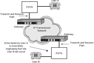
Figure 5: Echo originates from the far-end tail circuit.
What Makes Echo Perceptible?
As mentioned before, round-trip delay introduced into the voice path by voice-over-packet (VoP) networks such as Voice-over-IP can often cause existing echo originating from an analog tail circuit to become perceptible and even
annoying. Echo that originates between your telephone and the PSTN central office is not perceptible because it returns to your ear too quickly. Even echo from the far-end tail circuit usually returns quickly enough or is attenuated enough to not be heard. VoP network components, however, introduce into the voice path a fundamental and unavoidable end-to-end delay that often exceeds the 32-ms threshold mentioned earlier. If echo is produced in the far-end PSTN analog tail circuit, at least twice this delay (known as round-trip delay) will pass before the echo reaches the near-end talkers ear. Thus, even attenuated echo can become perceptible. Since near-end echo will not be heard, you can often correctly conclude that any perceptible echo originates from the far-end tail circuit. Figure 5 illustrates this point.
How Do Networks Deal With Echo?
To deal with unwanted echo, functional components known as echo cancellers are deployed in the local exchange, the VoIP-Gateway, or the VoIP PC terminal, usually as close as possible to the tail circuit that causes the echo. Referring back to Figure 5, an echo canceller next to the hybrid on User Bs side of the network faces out at User B and cancels the echo of User As voice that would otherwise be heard by User A.
To eliminate unwanted echo, echo cancellers form a mathematical model of the tail circuit they monitor. They then use this model (along with representations of the signal likely to be echoed, such as User As voice) to estimate the expected echo. This estimated echo is then subtracted from the speech originating on the tail circuit side of the echo canceller (User Bs voice). Thus, normal speech is allowed to pass through the echo canceller, but echoes of received speech are removed.
An interesting characteristic of most modern echo cancellers is their ability to adapt to signal and tail circuit conditions. In other words, at the start of a voice call, echo cancellers take some finite time to converge on the echo estimate that will be subtracted from far-end speech signals. For example, at the beginning of a VoIP telephone call that terminates through an analog tail circuit, echo may be perceptible but quickly diminishes as the echo canceller
converges. A point of failure (or poor performance) for many echo cancellers is when the talker at the far-end interrupts the near-end talker (a condition known as double-talk). Echo cancellers work with the assumption of a linear and time-invariant tail circuit. Double-talk, however, causes the tail circuit to appear to be non-linear, resulting in echo canceller divergence (in other words, its echo estimate becomes more inaccurate). In this case, the interrupting speech can become distorted.
IP Transmission Network
Echo heard by User A is most likely originating from the
User B tail circuit
User A Gateway Gateway User B PSTN PSTN
Transmit and Receive Path
Transmit and Receive Path
14
Silence Suppression and
Comfort Noise Generation
Testing Voice Quality
To more efficiently use bandwidth, voice-over-IP networks employ functionality referred to as silence suppression or voice activity detection. A voice activity detector (or VAD) is a component of a voice gateway or terminal that suppresses the packetization of voice signals between individual speech utterances, such as during the silent periods in a voice conversation. VADs generally operate on the send side of a gateway, and can often adapt to varying levels of noise vs. voice. That is, similar to adaptive jitter buffers and echo cancellers, VADs can converge on appropriate thresholds to optimize their performance for a given voice conversation. Since human conversations are essentially half-duplex in the long term, the use of a VAD can realize
approximately 50 percent reduction in bandwidth requirements over an aggregation of channels. Figure 6 depicts the behavior of a VAD and its parameters.
Figure 6: Voice Activity Detector (VAD) behavior.
While a VADs performance does not affect clarity directly, if it is not operating correctly it can certainly decrease the intelligibility of voice signals and overall conversation quality. Excessive front end clipping (FEC), for example, can make it difficult to understand what is said. Excessive hold-over time (HOT) can reduce network efficiency, and too little hold-over time can cause speech utterances to feel choppy and unconnected when cutting in, even in short speech pauses.
Complimentary to the transmit-side VAD, a Comfort Noise Generator (CNG) is a receive-side device. During periods of transmit silence, when no packets are sent, the receiver has a choice of what to present to the listener. Muting the channel (playing absolutely nothing) gives the listener the unpleasant impression that the line has gone dead. A receive-side CNG generates a local noise signal that it presents to the listener during silent periods. The match between the generated noise and the true background noise determines the quality of the CNG.
Traditionally, voice quality testing techniques involved comparing waveforms on a screen, and measuring signal-to-noise ratio (SNR) and total harmonic
distortion (THD) among others. These and other linear measurements are useful only in certain cases because they assume that changes to the voice waveform represent unwanted signal distortion. These testing methods also assume that telephony circuits are essentially linear. However, in VoIP and other voice-over-packet networks, particularly when low bit rate speech-codecs such as G.729 and G.723.1 are used, neither waveform preservation nor circuit linearity can be assumed. These codecs try to reproduce the subjective sound of the signal rather than the shape of the speech waveform, rendering traditional testing methods more or less ineffective. And, as discussed before, the bursty and time-insensitive nature of packet networks exposes the need for other testing methods as well. Finally, because of their heightened importance, the performance of echo cancellers, voice activity detectors, and other processes needs to be tested directly.
Speech Magnitude (dB)
Speech Detected Hold-Over
Sentence 1 Sentence 2 Noise Floor Signal-to-Noise Threshold Front-end Speech Clipping Signal Encoding Front-end Speech Clipping Signal Encoding
15
Measuring Clarity
Because of the inherent subjective nature of voice quality testing, one obvious method to quantify quality is to have relatively large numbers of human listeners rate voice quality as part of a controlled and well defined test process. The advantage of this method is that clarity evaluations are derived directly from the individuals who will experience the voice call. Another advantage is the statistical validity provided by numerous evaluators. This, in fact, has been the method used for many years and is defined as Mean Opinion Score (MOS) in ITU-T specification P.800.
In spite of its obvious advantages, MOS has one distinct and significant disadvantage: it is expensive both in time and effort. Parading tens or even hundreds of human listeners through a voice quality test lab to evaluate the performance of a single set of telephony devices or software products would seem not to be the most efficient method. Experimental conditions have to be tightly controlled, test results have to carefully analyzed, and the whole process needs to be repeated when new equipment or voice encoding methods are developed. So how can clarity be measured in a repeatable, objective, and reasonably inexpensive way?
One method is PSQM, or Perceptual Speech Quality Measurement, defined by ITU-T Recommendation P.861. Originally created to evaluate speech codecs, the PSQM algorithm provides a method by which speech within the voice
bandwidth of 3003400 Hz can be objectively measured for distortion, the effects of noise, and overall perceptual fidelity. Simply put, PSQM is an automated human listener.
PSQM evaluates the quality of voice signals in much the same way that non-linear codecs encode and decode voice signals. It evaluates whether a
particular voice signal is distorted with regards to what a human listener would find annoying and distracting. To do this, PSQM takes a clean voice sample and compares it to a more or less distorted version using a complex weighting method that takes into account what is perceptually important, for example, the physiology of the human ear and cognitive factors related to what human listeners are likely to notice. PSQM provides a relative score that indicates just how different the distorted signal is with respect to the original from the perspective of the human listener via the algorithm. PSQM shows whether the distorted voice signal is better or worse than the original. Because of the way PSQM works, this distortion score corresponds very closely to how a statistically large number of human listeners would react in the same test situation (for example, MOS).
PSQM was originally designed specifically to measure the perceived quality of voice as impacted by voice compression codecs. However, certain impairments, such as packet loss, introduced by data network transmission, are not
adequately reflected in PSQM scores. Therefore, an enhanced version of PSQM, known as PSQM+, was developed to correlate more to MOS scores in the presence of network impairments.
Another important model for measuring perceived clarity that has recently been developed is the Perceptual Analysis Measurement System (PAMS). PAMS uses a similar perceptual model as PSQM, and shares the purpose of providing a repeatable, objective means for measuring perceived voice quality. PAMS uses a different but effective signal processing model than PSQM, and produces different types of scores. It provides a Listening Quality Score and a Listening Effort Score, both which correlate to MOS scores and are on the same 1 to 5 scale.
16
Measuring Delay
As mentioned previously, end-to-end delay can have a significant effect on the quality of a voice conversation. Remember that delay does not affect the sound
of a voice conversation but rather the rhythm and feel of the conversation. There are two primary ways to measure delay in a voice-over-packet
environment. Acoustic PING and MLS Normalized Cross Correlation. Ideally, both methods should be used to ensure that delay measurements are accurate and consistent because delay can change in a dynamic VoIP environment.
Acoustic PING
Acoustic PING is just what you might expect from the name. A narrow audio spike is transmitted from one end of the audio channel to the other, and the time it takes to travel end-to-end is measured. This simple method, however, is susceptible to noise and attenuation because the actual spike can be masked by other noise spikes on the channel or strongly attenuated such that it will not be detected. In addition, the relative narrowness of the spike makes it vulnerable to packet loss (that is, the spike itself may only be one or two packets long). Acoustic PING should be augmented with other methods to ensure accuracy and consistency.
MLS Normalized Cross Correlation
It is possible to use digital signal processing (DSP) techniques in which a special test signal is transmitted onto the system under test and the received signal and original test signal are then analyzed together to determine end-to-end delay. This method, called MLS Normalized Cross Correlation, uses a test signal that sounds very much like white noise and, in fact, exhibits many of the same characteristics. Unlike white noise, maximum length sequence (MLS) noise is a repeatable and predictable noise pattern that enhances analysis calculations. Using this method, the delay value calculated is actually a subset of the information obtained. Delay calculated in this way is much more accurate, provides higher resolution results, and is more noise resistant than acoustic PING methods.
Measuring Echo
Several aspects exist in measuring echo. Initially, you may need to characterize echo levels and echo delay. In addition, you might need to measure how well echo cancellers deal with echo. Finally, you may find it very useful to evaluate just how annoying echo is to users of the telephony system. Each of these items are covered next.
Echo Characterization
Characterizing echo almost always involves measuring echo levels and the length of time it takes for an echo to return to the talker. The amount that echo is attenuated before it reaches the talkers ear is often referred to as echo return loss (ERL). ERL is an important parameter because many echo cancellers are unable to deal with echo that has not been attenuated by some amount. In addition, the time that passes before echo is heard, known as echo delay, must be within a certain window to allow echo cancellers of reasonable processing power to be effective. ERL and echo delay could be considered tail circuit design parameters and certainly have an impact on the type and configuration of the echo canceller used. It is also useful to know these echo characteristics so that decisions can be made as to whether an echo canceller is the right solution or whether tail circuit redesign is needed to solve a given echo problem.
17
Echo Cancellers
Measuring the actual echo that may or may not exist on the network should also be accompanied by a direct evaluation of echo canceller performance. To do this, test personnel often need to simulate tail circuit behavior (echo delay, ERL, and frequency response) and be able to control various aspects of that behavior. Important parameters to measure when evaluating an echo canceller are:
Convergence Timethe time required for an echo canceller to adapt to the local tail circuit and provide adequate echo reduction.
Cancellation Depththe reduction in echo strength achieved (measured in decibals).
Double-talk Robustnessa measure of whether the echo canceller looses its cancellation ability under conditions of simultaneous talking from both ends of the connection.
Perceived Annoyance Caused by Echo (PACE)
One very useful measure of the overall quality of a voice connection is to what extent echo is perceived as a problem by the users of that connection. Similar to voice clarity, this point is essentially a subjective judgement and requires very special measurement algorithms to achieve an objective, reliable, and
repeatable result. The ITU-T has defined methods by which echo characteristics can be measured: G.165 is an algorithm that uses white noise, G.168 uses speech frequency test signals. However, these methods seem best suited for laboratory testing and are not suitable for low bit rate codecs in which the waveform of the voice signal is not always preserved. But by using an objective, perception-based algorithm such as PSQM or PAMS described previously, it is possible to evaluate the effect echo has on a users perception of quality in both a test lab environment and in deployed VoP networks.
Measuring VADs
Another voice-over-packet device component whose performance can be measured directly is the voice activity detector. The goal in this case would be to measure front end clipping (FEC) and hold-over time (HOT), and perhaps comfort noise generation (CNG) match. Ideally, it is necessary to produce test signals that simulate the conditions the VAD will be presented with, or rather, predominant voice levels accompanied by low-level noise. One successful method is to produce a hybrid test signal comprised of a finite voice band noise burst accompanied by a very low level and distinct tracer dye tone. The noise burst (which simulates a speech utterance) and tracer dye tone are sent through a network containing a VAD and received at the other end. The received noise burst width is compared to the original to determine the FEC and the tracer dye tone is used to detect when the VAD closes (HOT).
18
Agilent Technologies Voice
Quality Test Solutions
Other important features of this powerful analysis tool include:
Agilent Technologies Telegra®VQT Application is a voice quality tester that you can use to directly and objectively quantify voice quality on telephony devices and systems. The VQT eliminates the need for the large numbers of subjective human listeners that have traditionally been used for this purpose, and provides measurement capabilities appropriate for the conditions found in emerging voice-over-packet environments. The VQT provides a direct measure of end-to-end delay, voice signal clarity, and echo. It also provides numerous other measurements and tools to evaluate conditions that affect voice quality including a Voice Activity Detector measurement, a DTMF Tone measurement, an Impulse Response measurement, and various signal transmission and audio channel emulation tools. The VQT supports and operates on multiple telephony interfaces including FXO and E&M.
Figure 7: Agilent Technologies’ Telegra VQT.
Intuitive and Easy to Learn
The VQT has been designed to closely match the way users are likely to test voice quality and it is, therefore, is easy to learn. For those unfamiliar with voice quality testing, the VQT provides common testing scenarios via its TaskList Navigator and simple operating instructions via its unique multi-mode embedded Help system. Measurement configuration and measurement results are displayed in a single-layer user interface so that users can work with the application with a minimum of navigation.
Clear Measurement Results
For novice users, important measurement results are clearly displayed in a pass/fail format. For experienced users, or those needing to drill deeper into the results, numerous statistics are provided and the graph can be manipulated and zoomed.
Customizable Automated Testing
The VQT provides users with the ability to easily create automated test scripts by manipulating the same user interface they would use for attended testing. These AutoTasker test scenarios can be used for long-term trending test scenarios, to perform measurements at odd hours of the day, or to make routine testing easier. Automated testing can also be controlled via common Windows-based remote control software.
19
About the Authors
Stefan Pracht
Stefan Pracht is a Product Marketing Manager for Agilent Technologies Network Systems Test Division focusing on voice, fax, and IP test solutions for next generation networks. Stefan has been instrumental in the development of Agilents VoIP business and is managing the definition and market deployment of the Telegra line of fax, voice quality, and VoIP test and analysis products.
During the last six years with Hewlett-Packard Company and now Agilent Technologies, he has worked on the definition and introduction of several products and services focusing on digital communications and telephony test and analysis systems. Stefan has developed cable modem and IP analysis system business strategies for a range of HP/Agilent products. Prior to joining Hewlett-Packard/Agilent Technologies, Stefan worked as a project manager for Deutsche Telekoms national and international ATM trials. Stefan holds a Bachelors of Science in Telecommunications degree from the University of Dieburg, Germany and has several years of experience in product definition, development, and introduction.
Dennis Hardman
Dennis Hardman is a Learning Products Engineer for Agilent
Technologies Network Systems Test Division and designs and writes end user documentation for a broad range of data communications and telecommunications analysis hardware and software products. Dennis also participates in user interface design and administers usability testing for the R&D teams to which he is assigned. Dennis holds a Bachelors of Science in Electrical Engineering degree from the University of Utah with an emphasis on communications technologies.
*5968-8428E*
5980-0989E Online assistance: http: //ww w.agilent .com/find/assist United States: (Tel) 1 8 00 452 4844 Canada: (Tel) 1 877 894 4414 (Fax) (905) 282 6495 China: (Tel) 800-810-0189 (Fax) 1-0800-650-0121 Europe: (Tel) (31 20) 547 2323 (Fax) (31 20) 547 2390 Japan: (Tel) (81) 426 56 7832 (Fax) (81) 426 56 7840 Korea: (Tel) (82-2) 2004-5004 (Fax) (82-2) 2004-5115 Latin America: (Tel) (305) 269 7500 (Fax) (305) 269 7599 Taiwan: (Tel) 080-004-7866 (Fax) (886-2) 2545-6723Other Asia Pacific Countries:
(Tel) (65) 375-8100 (Fax) (65) 836-0252
Product specifications and descriptions in this document subject to change without notice.
ãAgilent Technologies, Inc. 2000-2001
Printed in U.S.A. October 22, 2001
By internet, phone or fax, get assistance with all your Test and Measurement needs.
www.agilent.com
http://www.agilent.com/comms/onenetworks
Use this link to go directly to our network troubleshooting solutions:
Agilent Technologies’
Test and Measurement Support, Services, and Assistance
Agilent Technologies aims to maximize the value you receive, while minimizing your risk and problems. We strive to ensure that you get the test and measurement capabilities you paid for and obtain the support you need. Our extensive support resources and services can help you choose the right Agilent products for your applications and apply them successfully. Every instrument and system we sell has a global warranty. Support is available for at least five years beyond the production life of the product. Two concepts underlie Agilent’s overall support policy: “Our Promise” and “Your Advantage.”
Our Promise
Our Promise means your Agilent test and measurement equipment will meet its advertised performance and functionality. When you are choosing new equipment, we will help you with product information, including realistic performance specifications and practical recommendations from experienced test engineers. When you use Agilent equipment, we can verify that it works properly, help with product operation, and provide basic measurement assistance for the use of specified capabilities, at no extra cost upon request. Many self-help tools are available.
Your Advantage
Your Advantage means that Agilent offers a wide range of additional expert test and measurement services, which you can purchase according to your unique technical and business needs. Solve problems efficiently and gain a competitive edge by contracting with us for calibration, extra-cost upgrades, out-of-warranty repairs, and on-site education and training, as well as design, system integration, project management, and other professional engineering services. Experienced Agilent engineers and technicians worldwide can help you maximize your productivity, optimize the return on investment of your Agilent instruments and systems, and obtain dependable measurement accuracy for the life of those products.