R
LISTED
FM
APPROVED FMRC J.I.OX6A2.AF UL Listing File No. EX 4674
February 2007
Engineered
Carbon Dioxide (CO
2
)
Fire Suppression Systems
Design, Installation,
Operation and
Note: This Kidde Fire Systems Engineered Carbon Dioxide (CO2) Fire Suppression System Design, Installation, Operation, and Maintenance manual, P/N 81-CO2MAN-001, is for use only by qualified and factory-trained personnel with working knowledge of applicable standards such as NFPA, as well as a working knowledge of Kidde Fire Systems Engineered Carbon Dioxide (CO2) Fire Suppression System. Kidde Fire Systems does not authorize or recommend use of this Manual by others. The data contained herein is provided by Kidde Fire Systems as a guide only. It is not intended to be all inclusive and should not be substituted for professional judgement. Kidde Fire Systems believes the data to be accurate, but this data is provided without guarantee or warranty to its accuracy or completeness. Any questions concerning the information presented in this manual should be addressed to:
Kidde Fire Systems 400 Main Street Ashland, MA 01721 Phone: (508) 881-2000 Toll Free: (800) 872-6527 Fax: (508) 881-8920
TERMS AND ABBREVIATIONS
ABS: Absolute mA: Milliamperes
ADA: Americans with Disabilities Act N.C.: Normally Closed
AH: Ampere Hour NFPA: National Fire Protection
Association
AWG: American Wire Gauge N.O.: Normally Open
BIL: Basic Installation Level N2: Nitrogen
C: Common P/N: Part Number
CFM: Cubic Feet per Minute PED: Pressure Equipment Directive
CO2: Carbon Dioxide TC: Transport Canada
DC: Direct Current TCF: Temperature Correction Factor
DOT: Department of Transportation TPED: Transportable Pressure Equipment Direc-tive
FM: Factory Mutual UL/ULI: Underwriters Laboratories, Inc.
H20: Water ULC: Underwriters Laboratories of Canada
HVAC: Heating, Venting and Air Conditioning
V: Volts
Hz: Hertz (Frequency) Vac: Volts AC
The Kidde Fire Systems Engineered Carbon Dioxide (CO2) Fire Suppression System, uses pressurized equipment, and therefore you MUST notify personnel responsible or who may come into contact with the Engineered Carbon Dioxide (CO2) Fire Suppression System, of the dangers associated with the improper handling, installation, maintenance, or use of this equipment.
Fire suppression service personnel must be thoroughly trained by you in the proper handling, installation, service and use of the equipment in compliance with applicable regulations and codes and following the instructions in this manual, any Safety Bulletins and also the cylinder nameplate.
Kidde Fire Systems has provided warnings and cautions at a number of locations throughout this manual. These warnings and cautions are not comprehensive, but provide a good guide as to where caution is required. These warnings and cautions are to be adhered to at all times. Failure to do so may result in serious injury.
Material Safety Data Sheets (MSDS) for nitrogen and CO2 are available from Kidde Fire Systems. You should ensure your personnel are familiar with the information contained in these sheets.
DEFINITIONS
SUBJECT: SPECIFIC HAZARD
PROCEDURES FOR SAFELY HANDLING CYLINDERS
Before handling Kidde Fire Systems products, all personnel must be thoroughly trained in the safe handling of the containers as well as in the proper procedures for installation, removal, filling, and connection of other critical devices, such as flex hoses, control heads, discharge heads, and anti-recoil devices.
READ, UNDERSTAND and ALWAYS FOLLOW the operation and maintenance manuals, owners manuals, service manuals, etc., that are provided with the individual systems.
The following safety procedures are minimal standards that must be adhered to at all times. These are not
WARNING
Indicates an imminently hazardous situation which, if not avoided, could result in death, serious bodily injury and/or property damage.CAUTION
Indicates a potentially hazardous situation which, if not avoided, could result in property or equipment damage.WARNING
Because carbon dioxide reduces the available oxygen in the atmosphere, it will not support life. Care must be taken, and appropriate alarms shall be used, to ensure that all personnel are evacuated from the protected space prior to discharging the system. Suitable warning signs must be prominently displayed in clear view at the point of entry into the protected area to alert people to the asphyxiation properties of carbon dioxide.
WARNING
Pressurized (charged) cylinders are extremely hazardous and if not handledproperly are capable of violent discharge. This may result in serious bodily injury, death and property damage.
suitable hand truck, fork truck, roll platform or similar device must be used while maintaining properly secured cylinders at all times.
Rough Handling: Cylinders must not be dropped or permitted to strike violently against each other or other surfaces.
Storage: Cylinders must be properly secured and safely stored in an upright position and in accordance with any applicable regulation, rule or law. Safe storage must include some protections from tipping or being knocked over.
Nothing in this manual is intended as a substitution for professional judgment and will not serve to absolve any professional from acting in a manner contrary to applicable professional standards.
For additional information on safe handling of compressed gas cylinders, see CGA Pamphlet P-1 titled “Safe Handling of Compressed Gases in Containers”. CGA pamphlets may be purchased from The Compressed Gas Association, Crystal Square Two, 1725 Jefferson Davis Highway, Arlington, VA 22202.
SUBJECT: PROCEDURES FOR SAFELY HANDLING PRESSURIZED CYLINDERS
THESE INSTRUCTIONS MUST BE FOLLOWED IN THE EXACT SEQUENCE AS WRITTEN TO PREVENT SERIOUS INJURY, DEATH OR PROPERTY DAMAGE.
Shipping Cap
1. Each cylinder is factory equipped with a shipping cap over the cylinder valve connected to the cylinder collar. The shipping cap is a safety device and will provide a controlled safe discharge when installed if the cylinder is actuated accidentally.
2. AT ALL TIMES, the shipping cap must be securely installed over the cylinder valve and the actuation port protection cap shall be attached unless the cylinders are connected into the system piping during filling or performing testing.
Protection Cap
A protection cap is factory installed on the actuation port and securely chained to the valve to prevent loss. The cap is attached to the actuation port to prevent tampering or depression of the actuating pin. No attachments (control head, pressure control head) are to be connected to the actuation port during shipment, storage, or handling.
WARNING
Pressurized (charged) cylinders are extremely hazardous and if not handledproperly are capable of violent discharge. This will result in serious bodily injury, death and property damage.
THIS SEQUENCE FOR CYLINDER INSTALLATION MUST BE FOLLOWED AT ALL TIMES: 1. Position cylinder(s) in designed location and secure with cylinder bracket(s). 2. Remove safety (shipping) cap and actuation port protection cap.
3. Attach flex loops or swivel adapter to discharge heads. Connect assembly to system piping. Then attach assembly to cylinders.
4. Verify control head(s) are in the set position.
5. Install control head(s) on cylinder(s).
Removal From Service
1. Remove control head(s) from cylinder(s).
2. Remove discharge head from each cylinder valve.
3. Attach safety (shipping) protection cap and actuation port protection cap to each cylinder.
4. Remove cylinder from bracketing and properly secure to hand truck. Properly secure each cylinder for transport. Repeat for remaining cylinders.
WARNING
Flex hoses/swivel adapters must always be connected to the system piping and to the discharge heads before attaching the discharge heads to the cylinder valves in order to prevent injury in the event of inadvertent carbon dioxide discharge.WARNING
Control heads must be in the set position before attaching to the cylinder actuation port in order to prevent accidental discharge.WARNING
Do not remove the cylinder from the bracketing if the safety and protection capsare missing. Obtain a new safety (shipping) cap from a local gas supplier. Obtain a new actuation port protection cap from Kidde Fire Systems.
Foreword ... i
Terms and Abbreviations ... i
Safety Summary... iii
Definitions ... iii
Subject: Specific Hazard ... iii
CHAPTER 1 GENERAL INFORMATION
1-1 Introduction ... 1-1 1-2 Classification of Fire ... 1-1 1-3 General Characteristics of the System... 1-1 1-4 System Description ... 1-2 1-5 Type of Suppression System... 1-2 1-5.1 Total Flooding... 1-2 1-5.2 Local Application ... 1-2 1-6 General System Requirements ... 1-3 1-6.1 Safeguards ... 1-3 1-6.1.1 Adequate Path of Egress ... 1-3 1-6.1.2 Warning Signs and Personnel Education ... 1-3 1-6.1.3 Pre-Discharge Time Delays and Alarms ... 1-4 1-6.1.4 Stop Valves and Lockout Valves ... 1-4 1-6.1.5 Post-Release Warnings and Procedures ... 1-5 1-6.2 Storage ... 1-5 1-6.3 Discharge Characteristics ... 1-5 1-6.4 Actuation Methods ... 1-6 1-7 Applications ... 1-6 1-8 Extinguishing Properties of Carbon Dioxide ... 1-7 1-9 Physical Properties of Carbon Dioxide ... 1-7 1-10 Clean-up... 1-8
CHAPTER 2 COMPONENT DESCRIPTIONS
2-1 Fire Suppression System Components ... 2-1 2-2 CO2 Storage... 2-1 2-2.1 Cylinder and Valve Assemblies... 2-1 2-2.1.1 Valves ... 2-4 2-2.1.2 Cylinder Filling ... 2-5 2-2.2 Discharge Heads ... 2-7 2-2.2.1 Plain-nut Discharge Head ... 2-7 2-2.2.2 Grooved-nut Discharge Head ... 2-8 2-2.3 Flexible Hoses ... 2-11 2-2.4 Swivel Adapter ... 2-12 2-2.5 Manifold “Y” Fitting... 2-12 2-2.6 Cylinder Mounting Hardware... 2-13 2-2.6.1 Single or Double Cylinder Arrangements ... 2-13 2-2.6.1.1 Single Cylinder Straps. ... 2-13 2-2.6.1.2 Double Cylinder Straps ... 2-14 2-2.6.2 Multiple Cylinder Arrangements ... 2-15
2-3.1 Lever-Operated Control Head ... 2-19 2-3.2 Cable-Operated Control Head ... 2-20 2-3.3 Manual Control Equipment ... 2-21 2-3.3.1 Mechanical Pull Box... 2-22 2-3.3.2 Mechanical Pull Box Z-Bracket ... 2-22 2-3.3.3 Corner Pulleys ... 2-23 2-3.3.4 Tee Pulley... 2-23 2-3.3.5 Adapter ... 2-24 2-3.3.6 Cable Housing ... 2-24 2-3.3.7 Dual Pull Mechanism ... 2-25 2-3.3.8 Dual Pull Equalizer ... 2-26 2-3.3.9 1/16-inch Pull Cable ... 2-26 2-3.4 Electric Control Heads ... 2-27 2-3.4.1 Electric Control Heads ... 2-27 2-3.4.2 Electric and Cable-Operated Control Heads... 2-28 2-3.4.3 Explosion Proof Electric and Cable Operated Control Heads ... 2-29 2-3.5 Pneumatic Control Heads ... 2-30 2-3.5.1 Tandem Pneumatic Control Head ... 2-31 2-3.6 Components for Pneumatic Actuation Systems... 2-32 2-3.6.1 Pneumatic Cable Housing... 2-32 2-3.6.2 Heat Actuated Detector ... 2-33 2-3.6.3 Heat Collector ... 2-34 2-3.6.4 Vents ... 2-35 2-3.6.5 1/8-inch Copper Tubing ... 2-36 2-3.6.5.1 Fittings... 2-36 2-3.6.5.2 Rubber Grommet ... 2-37 2-3.6.6 3/16-inch Copper Tubing ... 2-37 2-3.7 Pressure Operated Control Heads ... 2-37 2-3.7.1 Pressure Operated Control Head ... 2-37 2-3.7.2 Lever and Pressure Operated Control Head... 2-38 2-3.7.3 Stackable Pressure Operated Control Head ... 2-39 2-3.8 Components for Pressure Operated Actuation Systems... 2-40 2-3.8.1 Nitrogen Pilot Cylinder and Bracket ... 2-40 2-3.8.2 Actuation Hose ... 2-41 2-3.8.3 Fittings... 2-42 2-4 Check Valves... 2-42 2-4.1 Check Valves (1/4-inch through 3/8-inch) ... 2-42 2-4.2 Check Valves (1/2-inch through 2-inch) ... 2-43 2-4.3 Check Valves (2 1/2-inch through 3-inch) ... 2-44 2-4.3.1 2 1/2-inch Welding Neck Flange... 2-45 2-4.3.2 3-inch Welding Neck Flange ... 2-45 2-4.3.3 3-Inch Flange Gasket ... 2-45 2-4.3.4 Nuts and Bolts... 2-45 2-5 Directional (Stop) Valves ... 2-46 2-5.1 Directional (Stop) Valves (1/2-inch through 2-inch)... 2-46 2-5.2 Directional (Stop) Valves (2 1/2-inch through 4-inch) ... 2-47 2-5.2.1 2 1/2-inch and 3-inch Valves ... 2-47
2-5.2.2 4-inch Valve... 2-48 2-5.2.3 4-inch Flange ... 2-48 2-5.2.4 4-inch Gasket... 2-48 2-5.2.5 Nuts and Bolts... 2-48 2-6 Lockout Valves ... 2-49 2-7 Discharge Nozzles ... 2-51 2-7.1 Multijet Nozzle, Type S ... 2-51 2-7.1.1 Flanged Nozzle Mounting Kit, Type S Nozzle ... 2-53 2-7.1.2 Aluminum Disc ... 2-56 2-7.1.3 Stainless Steel Disc ... 2-56 2-7.2 Multijet Nozzle, Type M... 2-56 2-7.3 Vent Nozzle, Type V ... 2-58 2-7.3.1 Flange and Cover Assembly, Type V Nozzle ... 2-59 2-7.4 Multijet Nozzle, Type L... 2-59 2-8 Auxiliary Equipment ... 2-60 2-8.1 Pressure Operated Switches ... 2-61 2-8.2 Pressure perated Trip ... 2-62 2-8.3 Pneumatic Time Delay ... 2-63 2-8.4 Pressure Operated Siren ... 2-65 2-8.5 Safety Outlet... 2-66 2-8.6 Discharge Indicator ... 2-67 2-8.7 Odorizer ... 2-68 2-8.7.1 Odorizer Protective Housing ... 2-68 2-8.7.2 Odorizer Cartridge ... 2-68 2-8.8 Main to Reserve Transfer Switch ... 2-69 2-8.9 Weigh Scale ... 2-70 2-8.10 Recharge Adapter ... 2-70 2-8.11 Blow-Off Fixture... 2-71 2-9 Instruction and Warning Plates ... 2-71 2-9.1 Main and Reserve Nameplates ... 2-71 2-9.2 Warning Signs ... 2-72 2-9.2.1 Vacate Warning Sign, P/N 06-281866-851... 2-72 2-9.2.2 Do Not Enter Warning Sign, P/N 06-281866-852 ... 2-73 2-9.2.3 Odorizer Warning Sign, P/N 06-281866-853 ... 2-73 2-9.2.4 Migration Warning Sign, P/N 06-281866-854 ... 2-74 2-9.2.5 Storage Warning Sign, P/N 06-281866-855 ... 2-74 2-9.2.6 Actuation Warning Sign, P/N 06-281866-856 ... 2-75 2-10 Hose Reel and Rack Systems ... 2-75
CHAPTER 3 DESIGN
3-1 Introduction ... 3-1 3-2 Hazard Survey, Definition and Analysis ... 3-1 3-3 Design for Safety ... 3-2 3-4 Applications ... 3-2 3-4.1 Total Flooding System ... 3-2
3-5 Total Flooding Systems... 3-3 3-5.1 Introduction ... 3-3 3-5.1.1 Enclosure... 3-3 3-5.1.2 Ventilation ... 3-4 3-5.1.3 Interlocks ... 3-4 3-5.1.4 Interconnected Volumes ... 3-4 3-5.2 Calculations for Surface Fires... 3-4 3-5.2.1 Extinguishing Concentrations... 3-4 3-5.2.2 Basic Total Flooding Quantity... 3-5 3-5.2.2.1 Ducts and Covered Trenches ... 3-7 3-5.2.3 Material Conversion Factor ... 3-7 3-5.2.4 Special Conditions... 3-10 3-5.2.4.1 Uncloseable Openings... 3-10 3-5.2.4.2 Forced Ventilation ... 3-13 3-5.2.4.3 Extreme Temperatures ... 3-14 3-5.2.5 Discharge Rates... 3-17 3-5.3 Calculations for Deep-Seated Fires ... 3-19 3-5.3.1 Flooding Factors ... 3-19 3-5.3.2 Special Conditions... 3-20 3-5.3.2.1 Uncloseable Openings... 3-21 3-5.3.2.2 Forced Ventilation ... 3-21 3-5.3.2.3 Extreme Temperatures ... 3-21 3-5.3.3 Discharge Rates... 3-21 3-5.4 System Design ... 3-24 3-5.4.1 Occupancy ... 3-24 3-5.4.2 Discharge Nozzles ... 3-25 3-5.4.3 Pressure Relief Venting ... 3-25 3-6 Local Application Systems ... 3-26 3-6.1 Carbon Dioxide Requirements... 3-26 3-6.1.1 Nozzle Location, Orientation, And Coverage Area ... 3-26 3-6.1.2 Rate Of Discharge ... 3-26 3-6.1.3 Duration Of Liquid Discharge ... 3-26 3-6.1.4 Quantity Of Carbon Dioxide ... 3-27 3-6.2 Rate-by-Area Method ... 3-27 3-6.2.1 Overhead Nozzles ... 3-27 3-6.2.1.1 Nozzle Coverage and Carbon Dioxide Requirements... 3-27 3-6.2.1.2 Nozzle Positioning ... 3-35 3-6.2.2 Tankside Type "L" Nozzle ... 3-36 3-6.2.2.1 Rate for Liquid Surface ... 3-36 3-6.2.2.2 Rate for Coated Surface... 3-38 3-6.2.2.3 Nozzle Coverage and Carbon Dioxide Requirements... 3-40 3-6.3 Rate by Volume Method ... 3-44 3-6.3.1 Assumed Enclosure ... 3-44 3-6.3.2 Discharge Rate ... 3-44 3-6.3.3 Nozzles ... 3-49 3-6.4 Safeguards for Local Application Systems... 3-50 3-7 Combination Systems... 3-51
3-8 Multiple Hazard Systems ... 3-53 3-9 Pressure Operated Sirens... 3-54 3-10 Extended Discharge Systems... 3-55 3-10.1 Increased Agent Supply ... 3-55 3-10.2 Secondary System ... 3-55 3-10.3 Common Applications ... 3-56 3-10.3.1 Deep-Fat Cookers ... 3-56 3-10.3.2 Enclosed Rotating Electrical Equipment ... 3-56 3-10.3.2.1 Recirculating Ventilation... 3-56 3-10.3.2.2 Dampered, Non-Recirculating Ventilation... 3-56 3-11 Agent Storage Banks ... 3-57 3-11.1 Agent Supply... 3-57 3-11.2 Main and Reserve Supplies ... 3-59 3-11.3 Cylinder Location ... 3-59 3-11.4 Single and Double Cylinder Arrangements ... 3-60 3-11.5 Multiple Cylinder Arrangements ... 3-60 3-12 Manifold and Pipe Network Design... 3-60 3-12.1 Pipe and Fitting Specifications... 3-60 3-12.1.1 Pipe Specifications ... 3-60 3-12.1.2 Fitting Specifications ... 3-61 3-12.1.3 Tubing Specifications... 3-61 3-12.1.4 Closed Piping Sections ... 3-61 3-12.2 Pipe Size Estimates ... 3-61 3-12.3 Pipe Hangers and Supports ... 3-62 3-12.4 Cylinder Manifolds... 3-62 3-12.4.1 Manifold arrangements ... 3-62 3-12.4.1.1 End... 3-62 3-12.4.1.2 Center... 3-62 3-12.4.1.3 H ... 3-63 3-12.4.1.4 Main And Reserve ... 3-63 3-12.4.2 Manifold Pipe Selection ... 3-64 3-12.4.2.1 Single Pipe Size Manifolds ... 3-64 3-12.4.2.2 Stepped Pipe Size Manifolds ... 3-64 3-12.4.3 Manifold Objects ... 3-64 3-12.4.3.1 Safety Outlets ... 3-64 3-12.4.3.2 Discharge Indicators... 3-65 3-12.4.3.3 Lockout Valve... 3-65 3-12.4.3.4 Directional (Stop) Valves ... 3-65 3-12.4.3.5 Pneumatic Time Delays... 3-65 3-12.4.3.6 Pressure Operated Sirens... 3-66 3-12.4.3.7 Check Valves... 3-66 3-12.4.3.8 Pressure Operated Switches ... 3-66 3-12.4.3.9 Odorizers ... 3-66 3-12.5 Distribution Networks ... 3-66 3-12.5.1 Hydraulic Calculations... 3-66
3-12.5.4 Electrical Clearances ... 3-67 3-13 Actuation System Design ... 3-67 3-13.1 Discharge Heads... 3-67 3-13.2 Cylinder Actuation... 3-67 3-13.2.1 Actuation With A Control Head... 3-67 3-13.2.2 Actuation With Manifold Backpressure... 3-67 3-13.3 Actuation Classifications ... 3-68 3-13.3.1 Automatic ... 3-68 3-13.3.2 Normal Manual ... 3-68 3-13.3.3 Emergency Manual... 3-68 3-13.4 Control Systems ... 3-69 3-13.4.1 Lever Operated Actuation... 3-69 3-13.4.2 Cable Operated Actuation ... 3-70 3-13.4.2.1 Tandem Control Heads ... 3-70 3-13.4.2.2 Multiple Pull Stations ... 3-70 3-13.4.2.3 Multiple Cylinder Banks... 3-70 3-13.4.3 Pneumatic Heat Detector Operated Actuation... 3-70 3-13.4.3.1 Tandem Control Heads ... 3-71 3-13.4.3.2 Main and Reserve System Actuation ... 3-71 3-13.4.4 Electrically Operated Actuation ... 3-71 3-13.4.5 Nitrogen Pressure Operated Actuation ... 3-71 3-14 Detection Devices, Alarm Devices And Control Panels ... 3-72 3-14.1 Suppression Control Panels ... 3-72 3-14.2 System Power Supply... 3-72 3-14.3 Automatic Detection... 3-72 3-14.4 Manual Controls... 3-73 3-14.5 Notification ... 3-73 3-14.6 Supervision of Controls... 3-73 3-14.7 Main and Reserve System Actuation ... 3-73 3-15 Auxiliary Equipment and Systems ... 3-73 3-15.1 Pressure Operated Switches ... 3-74 3-15.2 Pressure Operated Trips... 3-74 3-16 Hand Hose Line Systems... 3-75 3-16.1 Uses ... 3-76 3-16.2 Safety Requirements ... 3-76 3-16.3 Location ... 3-77 3-16.4 System Design ... 3-77 3-16.4.1 Flow Rate ... 3-77 3-16.4.2 Minimum Agent Quantity ... 3-78 3-16.4.3 Multiple Stations ... 3-79 3-16.4.4 Carbon Dioxide Supply ... 3-79 3-16.4.5 Actuation ... 3-79
CHAPTER 4 INSTALLATION
4-1 Introduction ... 4-1 4-2 General Installation Requirements... 4-1 4-3 Installation of Suppression Systems ... 4-1
4-3.1 Discharge Pipe and Fittings ... 4-1 4-3.2 Pressure Operated Actuation Pipe, Tubing and Fittings ... 4-2 4-3.3 Discharge Manifold... 4-4 4-3.4 Manifold “Y” Fitting... 4-5 4-3.5 Carbon Dioxide Cylinder Assemblies ... 4-5 4-3.6 Flexible Discharge Hose to Piping ... 4-21 4-3.7 Swivel Adapter to Piping ... 4-21 4-3.8 Discharge Head to Cylinder Valve... 4-22 4-3.9 Check Valves and Directional (Stop) Valves ... 4-22 4-3.9.1 2-inch and Smaller Check Valves and Directional (Stop) Valves ... 4-22 4-3.9.2 2-1/2 inch and Larger Check Valves and Directional (Stop) Valves ... 4-22 4-3.10 Lockout Valves ... 4-23 4-3.10.1 Stem Seal Adjustment ... 4-23 4-3.10.2 Wiring Diagram ... 4-23 4-3.11 Pneumatic Time Delay ... 4-24 4-3.12 Discharge Nozzles ... 4-25 4-4 Actuation Systems ... 4-25 4-4.1 Lever Operated Control Head... 4-25 4-4.2 Cable Operated Actuation System Components ... 4-26 4-4.3 Cable Operated Control Head... 4-26 4-4.4 Pull Boxes ... 4-27 4-4.5 Main to Reserve Transfer Switch ... 4-28 4-4.6 Tandem Control Head ... 4-29 4-4.7 Electric Control Heads... 4-30 4-4.8 Electric and Cable Operated Control Heads ... 4-31 4-4.9 Pneumatic Heat Actuated Detection (HAD) System Components ... 4-33 4-4.9.1 HAD ... 4-33 4-4.9.2 Tubing... 4-34 4-4.9.3 Manometer Test Procedure... 4-36 4-4.9.4 Control Head Vent Test ... 4-36 4-4.9.4.1 To Test Pneumatic Detectors And/or System Tubing For Tightness... 4-37 4-4.9.4.2 Other Use For Manometer ... 4-37 4-4.9.5 Heat Collector ... 4-37 4-4.9.6 Pneumatic, Main-to-Reserve Valve ... 4-37 4-4.10 Pneumatic Control Head... 4-38 4-4.11 Nitrogen Actuation Station ... 4-40 4-4.12 Pressure Operated Control Heads ... 4-42 4-4.13 Lever and Pressure Operated Control Heads ... 4-42 4-5 Auxiliary Components... 4-43 4-5.1 Pressure Operated Switches ... 4-43 4-5.2 Pressure Operated Trip ... 4-45 4-5.3 Pressure Operated Siren ... 4-46 4-5.4 Odorizer ... 4-47 4-5.5 Safety Outlet... 4-48 4-5.6 Discharge Indicator ... 4-48
4-7.1 Pre-Commission Inspection ... 4-53 4-7.2 Commissioning Procedure ... 4-53 4-7.3 Enclosure Inspection ... 4-54 4-7.4 System Inspection ... 4-54 4-7.5 Labeling ... 4-54 4-7.6 Operational Tests of the Individual Components ... 4-54 4-7.7 Full Discharge Test... 4-55 4-7.8 Commissioning the System ... 4-56 4-7.9 References and Checklists ... 4-56
CHAPTER 5 OPERATION
5-1 Introduction ... 5-1 5-2 Automatic Operation ... 5-1 5-3 Manual Operation ... 5-1 5-3.1 Cable Operated Systems... 5-1 5-3.2 Electric Systems ... 5-1 5-3.3 Systems Equipped with Remote Nitrogen Actuator... 5-2 5-4 Emergency Operation ... 5-2 5-4.1 Local Manual Operation - All Systems ... 5-2 5-5 Hose Reel or Rack Systems ... 5-3 5-5.1 Remote Manual Operation ... 5-3 5-5.2 Local Manual Operation ... 5-4 5-6 Main and Reserve Systems... 5-5 5-7 Lockout Valves ... 5-5
CHAPTER 6 MAINTENANCE
6-1 General ... 6-1 6-2 Preventive Maintenance ... 6-1 6-3 Inspection Procedures - Monthly ... 6-2 6-4 Semi-Annual Weighing of CO2 Cylinders... 6-4 6-4.1 Weighing (using Kidde Fire Systems Weigh Scale) ... 6-4 6-4.2 Weighing (without Kidde Fire Systems Weigh Scale) ... 6-5 6-4.3 Electric Control Head Test ... 6-5 6-4.4 Pressure Switch Test ... 6-6 6-4.5 Verify Odorizer Cartridge ... 6-6 6-5 Annual Maintenance ... 6-6 6-5.1 Equipment Inspection... 6-6 6-5.2 Distribution Piping Blow Out ... 6-6 6-5.3 Complete System Inspection ... 6-7 6-5.4 Pneumatic Detection System Tests ... 6-7 6-5.4.1 Pneumatic Control Head Test - Pressure Setting... 6-7 6-5.4.2 Control Head Vent Test... 6-9 6-5.4.3 Test for Leakage of System Tubing and Detectors ... 6-9 6-5.4.4 Troubleshooting of Pneumatic Detection System ... 6-10 6-6 5 Year and 12 Year Inspection and Test Guidelines ... 6-10 6-6.1 Carbon Dioxide and Nitrogen Cylinders ... 6-10 6-6.2 Flexible Hoses ... 6-11 6-7 Cleaning ... 6-11
6-8 Nozzle Service ... 6-11 6-9 Repairs... 6-11 6-10 Removal of Cylinders... 6-11 6-10.1 CO2 Cylinders... 6-11 6-10.2 Nitrogen Pilot Cylinders... 6-12 6-11 Installation of Cylinders ... 6-13 6-11.1 CO2 Cylinders... 6-13 6-11.2 Nitrogen Pilot Cylinders... 6-13
CHAPTER 7 POST-DISCHARGE MAINTENANCE
7-1 General ... 7-1 7-2 Post Fire Maintenance... 7-1 7-3 Cylinder Recharge... 7-2 7-3.1 Carbon Dioxide Agent ... 7-3 7-3.2 CO2 Cylinders... 7-3 7-3.2.1 CO2 Cylinder Leak Test ... 7-4 7-3.3 Nitrogen Pilot Cylinders: ... 7-6 7-4 Hose Reel or Rack System... 7-7 7-5 Odorizer ... 7-8
CHAPTER 8 PARTS LIST
8-1 Parts list ... 8-1
APPENDIX A FORMULA DERIVATIONS
A-1 Theoretical CO2 Extinguishing Concentration for a Total Flooding System... A-1 A-2 Quantity of CO2 Required for a Total Flooding System Under a Free Efflux
Flooding Condition ... A-1 A-3 Derivation of the Material Conversion Factor (MCF)... A-2 A-4 Rate of Carbon Dioxide Loss Through an Opening in an Enclosure... A-2 A-5 Discharge Rates for Deep Seated Fires... A-3
APPENDIX B OBSOLETE EQUIPMENT
B-2 Obsolete Equipment ... B-1 B-3 Mercury Check... B-1 B-3.1 Description ... B-1 B-3.2 Installation... B-3 B-4 Pneumatic Transmitter... B-4 B-4.1 Description ... B-4 B-4.2 Installation... B-5 B-5 Pneumatic Control Head (1-inch, 40-second) ... B-6 B-5.1 Description ... B-6 B-5.2 Installation... B-6 B-6 Pneumatic Main-to-Reserve Valve ... B-7
Figure Name Page Number
2-1 25 through 50 lb. Carbon Dioxide Cylinders, Bent Siphon Tube ... 2-2 2-2 75 and 100 lb. Carbon Dioxide Cylinder, Straight Siphon Tube ... 2-3 2-3 I/2-inch Type “I” Cylinder Valve... 2-4 2-4 5/8-inch Type “I” Cylinder Valve ... 2-5 2-5 Pressure vs. Temperature for CO2 Cylinders ... 2-6 2-6 Discharge Head, Plain Nut... 2-7 2-7 Installation of Plain Nut Discharge Head to Cylinder Valve ... 2-8 2-8 Discharge Head, Grooved Nut... 2-9 2-9 Installation of Grooved Nut Discharge Head to Cylinder Valve ... 2-10 2-10 1/2-inch Flex Hose ... 2-11 2-11 3/4-inch Flex Hose ... 2-11 2-12 Swivel Adapter ... 2-12 2-13 Manifold “Y” Fitting ... 2-12 2-14 Single Cylinder Straps ... 2-13 2-15 Double Cylinder Straps ... 2-14 2-16 Multiple Cylinder Mounting, Arrangement A ... 2-15 2-17 Multiple Cylinder Mounting, Arrangement B ... 2-15 2-18 Multiple Cylinder Mounting, Arrangement C ... 2-16 2-19 Cylinder Rack and Framing, Example Arrangement... 2-18 2-20 Lever-Operated Control Head ... 2-20 2-21 Cable-Operated Control Head ... 2-21 2-22 Cable-Operated Control Heads in Tandem ... 2-21 2-23 Mechanical Pull Box... 2-22 2-24 Mechanical Pull Box Bracket ... 2-22 2-25 Corner Pulleys ... 2-23 2-26 Tee Pulley... 2-24 2-27 EMT Adapter ... 2-24 2-28 Cable Housing ... 2-25 2-29 Dual Pull Mechanism ... 2-25 2-30 Dual Pull Equalizer ... 2-26 2-31 Electric Control Head... 2-27 2-32 Electric Control Head (Cover Removed)... 2-28 2-33 Electric and Cable-Operated Control Head ... 2-29 2-34 Explosion Proof Electric and Cable Operated Control Head ... 2-30 2-35 Pneumatic Control Head ... 2-31 2-36 Tandem Pneumatic Control Head ... 2-32 2-37 Pneumatic Cable Housing... 2-33 2-38 Heat Actuated Detector (HAD), Industrial... 2-34 2-39 Heat Collector ... 2-35 2-40 Fittings... 2-36 2-41 3/16-inch Pneumatic Tubing... 2-37 2-42 Pressure Operated Control Head ... 2-38 2-43 Lever and Pressure Operated Control Head... 2-39 2-44 Stackable Pressure Operated Control Head... 2-40 2-45 Nitrogen Pilot Cylinder and Bracket ... 2-41 2-46 1/4-inch Actuation Hose ... 2-41 2-47 Fittings... 2-42 2-48 Check Valves (1/4-inch and 3/8-inch)... 2-43 2-49 Check Valves (1/2-inch to 1-1/4-inch) ... 2-43 2-50 Check Valves (1-1/2-inch to 2-inch) ... 2-44 2-51 Check Valves (2 1/2-inch to 3-inch) ... 2-45
Figure Name Page Number
2-54 Directional (Stop) Valve (4-inch)... 2-48 2-55 CO2 Lockout Valve with Limit Switch ... 2-49 2-56 Multijet Nozzle, Type S ... 2-52 2-57 Multijet Nozzle, Type S Flanged ... 2-53 2-58 Flanged Nozzle Mounting Kit (Orifice Protection Only) ... 2-54 2-59 Flanged Nozzle Mounting Kit (Duct or Enclosure Mounting) ... 2-55 2-60 Flange Mounting Hole Pattern ... 2-56 2-61 Multijet Nozzle, Type M... 2-57 2-62 Vent Nozzle, Type V ... 2-58 2-63 Flange and Cover Assembly, Type “V” Nozzle... 2-59 2-64 Multijet Nozzle, Type L ... 2-60 2-65 Pressure Operated Switch ... 2-61 2-66 Pressure Operated Switch, Explosion Proof ... 2-62 2-67 Pressure Operated Trip... 2-62 2-68 Pneumatic Time Delay ... 2-63 2-69 Pneumatic Time Delay, Detail ... 2-64 2-70 Pneumatic Time Delay with Manual Control Head ... 2-65 2-71 Pressure Operated Siren ... 2-66 2-72 Safety Outlet ... 2-67 2-73 Discharge Indicator... 2-67 2-74 Odorizer Protective Housing ... 2-68 2-75 Odorizer Cartridge ... 2-68 2-76 Main to Reserve Transfer Switch ... 2-69 2-77 Weigh Scale ... 2-70 2-78 Charging Adapter... 2-70 2-79 Blow-Off Fixture ... 2-71 2-80 Main and Reserve Nameplates ... 2-72 2-81 Sign in Every Protected Space ... 2-72 2-82 Sign at Every Entrance to Protected Space ... 2-73 2-83 Sign at Every Entrance to Protected Space for Systems with a Wintergreen Odorizer .... 2-73 2-84 Sign in Every Nearby Space Where CO2 Can Accumulate to Hazardous Levels ... 2-74 2-85 Sign Outside Each Entrance to CO2 Storage Rooms ... 2-74 2-86 Sign at Each Manual Actuation Station... 2-75 2-87 Hose-to-Hose Reel Connection... 2-76 2-88 Hose-to-Pipe Rack Connection ... 2-77 2-89 Hose Assembly... 2-78 2-90 Horn and Valve Assembly ... 2-79 2-91 Handle and Horn Clips ... 2-80 2-92 Model HR-1 Instruction Plate ... 2-81 3-1 Minimum Design CO2 Concentration ... 3-8 3-2 Calculated CO2 Loss RateW ... 3-11 3-3 Nozzle Aiming ... 3-35 3-4 Partial Enclosure Flow Rate Reduction* ... 3-45 3-5 Nozzle Placement Example... 3-50 3-6 Example of an "End" Manifold... 3-62 3-7 Example of a "Center" Manifold... 3-63 3-8 Example of an "H" Manifold ... 3-63 3-9 Example of a "Main and Reserve" "End" Manifold ... 3-64 3-10 Pilot Cylinder Position within Manifold ... 3-68 3-11 Pressure Trip Applications ... 3-74 3-12 Typical Hand Hose Line System with Rack ... 3-75 3-13 Typical Hand Hose Line System with Reel... 3-76
Figure Name Page Number
4-1 Typical Manifold Layout ... 4-4 4-2 Manifold “Y” Fitting ... 4-5 4-3 Typical Cylinder Strap Location ... 4-6 4-4 Rack Framing - 3 to 6 Cylinders (50 and 75 lb. Capacity), Single Row ... 4-7 4-5 Rack Framing - 7 to 12 Cylinders (50 and 75 lb. Capacity), Single Row ... 4-8 4-6 Cylinder Racks (50 and 75 lb. Capacity), Single Row... 4-9 4-7 Rack Framing - 5 to 12 Cylinders (50 and 75 lb. Capacity), Double Row (One Side) ... 4-10 4-8 Rack Framing - 13 to 24 Cylinders (50 and 75 lb. Capacity), Double Row (One Side) .... 4-11 4-9 Cylinder Racks (50 and 75 lb. Capacity), Double Row (One Side) ... 4-12 4-10 Rack Framing - 5 to 12 Cylinders (50 and 75 lb. Capacity), Double Row (Two Sides)... 4-13 4-11 Rack Framing - 13 to 24 Cylinders (50 and 75 lb. Capacity), Double Row (One Side) .... 4-14 4-12 Cylinder Racks (50 and 75 lb. Capacity), Double Row (Two Sides) ... 4-15 4-13 Rack Framing - 6 to 10 Cylinders (100 lb. Capacity), Single Row ... 4-16 4-14 Cylinder Racks (100 lb. Capacity), Single Row ... 4-17 4-15 Rack Framing - 5 to 12 Cylinders (100 lb. Capacity), Double Row (One Side) ... 4-18 4-16 Rack Framing - 13 to 24 Cylinders (100 lb. Capacity), Double Row (One Side) ... 4-19 4-17 Cylinder Racks (100 lb. Capacity), Double Row (One Side) ... 4-20 4-18 Swivel Adapter to Piping ... 4-21 4-19 Switch When Ball Valve is in Fully Open Position ... 4-24 4-20 Switch When Ball Valve is in Fully Closed Position... 4-24 4-21 Wiring Diagram with Single Solenoid (Main and Reserve) ... 4-28 4-22 Wiring Diagram with Dual Solenoid (Main and Reserve) ... 4-28 4-23 Cable Operated Control Heads ... 4-29 4-24 Electric Control Heads ... 4-30 4-25 Electric and Cable Operated Control Heads ... 4-32 4-26 Pneumatic Detector (HAD) ... 4-34 4-27 Manometer Pneumatic Detection... 4-35 4-28 Heat Collector ... 4-37 4-29 Pneumatic Main-to-Reserve Valve ... 4-38 4-30 Pneumatic Control Head ... 4-39 4-31 Tandem Pneumatic Control Head ... 4-40 4-32 Nitrogen Actuation Station ... 4-41 4-33 Pilot Actuation Fittings... 4-41 4-34 Pressure Operated Control Heads... 4-42 4-35 Lever and Pressure Operated Control Heads ... 4-43 4-36 Pressure-Operated Switches... 4-44 4-37 Pressure Operated Switches, Explosion Proof ... 4-45 4-38 Pressure Operated Trip ... 4-45 4-39 Pressure Operated Siren ... 4-46 4-40 Odorizer Installation... 4-47 4-41 Safety Outlet... 4-48 4-42 Discharge indicator ... 4-48 4-43 Hose Reel Installation... 4-49 4-44 Hose Rack Installation ... 4-50 4-45 Hose Assembly ... 4-50 4-46 Horn and Valve Assembly ... 4-51 4-47 Handle and Horn Clips ... 4-51 6-1 Nitrogen Temperature vs. Pressure Data ... 6-3 6-2 Carbon Dioxide Cylinder Weighing Scale ... 6-4 6-3 Manometer Pneumatic Detection... 6-8
Figure Name Page Number
7-2 5/8-inch Type “I” Cylinder Valve ... 7-6 7-3 Nitrogen Temperature vs. Pressure Data... 7-7 B-1 3-Well Mercury Check ... B-2 B-2 3-Well Mercury Check - Installation Detail ... B-3 B-3 Pneumatic Transmitter ... B-5 B-4 Pneumatic Control Head (1-inch, 40-second) ... B-6 B-5 Pneumatic Main-to-Reserve Valve ... B-7
Table Name Page Number
1-1 Physical Properties of Carbon Dioxide ... 1-8 2-1 Safety Disc Information ... 2-4 2-2 CO2 and H20 Capacity Correlation ... 2-6 2-3 Single Cylinder Strap Dimensions... 2-13 2-4 Double Cylinder Strap Dimensions... 2-14 2-5 Framing Kits - One Row, 3 through 15 Cylinders ... 2-17 2-6 Cable Housing Part Numbers ... 2-25 2-7 1/16-inch Pull Cable Lengths ... 2-26 2-8 Electric Control Heads ... 2-28 2-9 Electric and Cable Operated Control Heads ... 2-29 2-10 Explosion Proof Control Heads ... 2-30 2-11 Pneumatic Control Head Settings ... 2-31 2-12 Pneumatic Cable Housing Part Numbers ... 2-33 2-13 Vent Size... 2-35 2-14 1/8-inch Copper Tubing Part Numbers ... 2-36 2-15 3/16-inch Copper Tubing Part Numbers ... 2-37 2-16 1/4-inch Actuation Hose Part Numbers ... 2-42 2-17 Check Valve Dimensions (1/4-inch through 3/8-inch) ... 2-43 2-18 Check Valve Dimensions (1/2-inch through 1-1/4-inch) ... 2-43 2-19 Check Valve Dimensions (1-1/2-inch through 2-inch) ... 2-44 2-20 Check Valve Dimensions (1 1/2-inch through 2-inch)... 2-47 2-21 CO2 Lockout Valve with Limit Switch Specifications... 2-50 2-22 Type S Nozzles ... 2-51 2-23 Flanged Nozzle Mounting Kit BOM ... 2-53 2-24 Type M Nozzles ... 2-57 2-25 Type V Vent Nozzles... 2-58 2-26 Type L Nozzles ... 2-60 2-27 Hose Reel and Rack System Part Numbers ... 2-75 3-1 Minimum Carbon Dioxide Concentrations for Extinguishment ... 3-4 3-2 Volume Factors - Surface Fires (For 34% CO2 Concentration), US Units ... 3-6 3-2 Volume Factors - Surface Fires (For 34% CO2 Concentration), Metric Units ... 3-7 3-3 Volume Factors for Deep Seated Hazards ... 3-20 3-4 Type “M” Multijet Nozzle (US Units)... 3-29 3-4 Type “M” Multijet Nozzle (Metric Units) ... 3-30 3-5 Type “S” Multijet Nozzle (US Units) ... 3-31 3-5 Type “S” Multijet Nozzle (Metric Units)... 3-32 3-6 Aiming Factors for Angular Placement of Nozzles1 ... 3-35 3-7 Liquid Surfaces1 (US Units)... 3-36 3-7 Liquid Surfaces1 (Metric Units) ... 3-37 3-8 Coated Surfaces1 (US Units) ... 3-38 3-8 Coated Surfaces1 (Metric Units)... 3-39 3-9 Pipe Size Estimates ... 3-61 3-10 Control Head Actuation Features ... 3-69 3-11 Corner Pulley Quantity and Cable Length Limits ... 3-70 3-12 Nitrogen Pilot Line Length Limitations ... 3-72 3-13 Equivalent Lengths of Hand Hose Line Components (US Units) ... 3-77 3-14 Equivalent Lengths of Hand Hose Line Components (Metric Units) ... 3-78 4-1 Maximum Horizontal Pipe Hanger and Support Bracing1... 4-3
Table Name Page Number
4-4 Corner Pulley and Cable Limitations... 4-26 6-1 Preventive Maintenance Schedule ... 6-2 8-1 Cylinders and Associated Equipment... 8-1 8-2 Manual and Pressure Control Equipment ... 8-2 8-3 Electric Control Equipment ... 8-2 8-4 Remote Control Equipment, Cable... 8-2 8-5 Pneumatic Control Equipment... 8-3 8-6 Check Valves ... 8-4 8-7 Directional (Stop) Valves ... 8-4 8-8 Lockout Valves ... 8-5 8-9 Hose Equipment ... 8-5 8-10 Auxiliary Equipment ... 8-6 8-11 Carbon Dioxide Computer Program ... 8-6 8-12 Manuals ... 8-7 8-13 Maintenance and Repair Parts... 8-7 8-14 Carbon Dioxide Nozzles ... 8-8 8-15 Nozzle Identification... 8-8 8-16 Carbon Dioxide Nozzles, Accessories ... 8-9 8-17 CO2 Valves Maintenance, Repair and Spare Parts ... 8-9 8-18 Cylinder Rack and Framing Components ... 8-9 8-19 Framing Kits - One Row, 3 through 15 Cylinders ... 8-13 8-20 Framing Kits - Two Rows (One Side), 5 through 17 Cylinders... 8-14 8-21 Framing Kits - Two Rows (One Side), 18 through 30 Cylinders ... 8-15 B-1 Pneumatic Control Head (1-inch, 40-second), Settings... B-6 C-1 TPED and PED Approved Equipment for European Community Only*... C-1
CHAPTER 1
GENERAL INFORMATION
1-1 INTRODUCTION
The Kidde Fire Systems carbon dioxide fire suppression system is an engineered, special-hazard system utilizing a fixed pipe and nozzle distribution network, hose reels, or a combination of both. These systems provide fire protection, using carbon dioxide (CO2) as the extinguishant, designed in accordance with the National Fire Protection Association (NFPA) 12, "Standard on Carbon Dioxide Extinguishing Systems", (latest edition). All components referenced in this manual are listed by Underwriters Laboratories (UL) and approved by Factory Mutual (FM), unless as noted.
1-2 CLASSIFICATION OF FIRE
The classification of fire is defined as the following:
• Class A: Surface Type Fires; wood or other cellulose-type material (ordinary combustibles) • Class B: Flammable liquids
• Class C: Energized electrical equipment
• Class D: Combustible metals (such as magnesium, sodium, zirconium, potassium, and titanium, or reactive metals, metal hydrides and chemicals containing their own oxygen supply)
• Class K: Combustible cooking media (vegetable or animal oils and fats)
Note: Kidde Fire Systems carbon dioxide fire suppression system is not suited for Class D type of fires.
Carbon dioxide is an effective agent for Class A, Class B, Class C, and Class K hazards. Carbon dioxide must be applied with due consideration of the hazard being protected and its contents. Carbon dioxide shall not be used on Class D hazards, such as magnesium, potassium, sodium, and cellulose nitrate. These Class D hazards can only be controlled by special extinguishing agents and procedures.
1-3 GENERAL CHARACTERISTICS OF THE SYSTEM
Carbon dioxide fire suppression systems are used for applications where the potential property damage and business interruption from fire are high. Carbon dioxide can control and suppress fires in easily ignitable fast-burning substances such as flammable liquids. It is also used on fires involving electrically energized equipment and, in some instances, on fires in ordinary combustibles such as paper, cloth, and other cellulose materials.
Carbon dioxide is a colorless, odorless, electrically non-conductive gas with a density approximately 50% greater than air. When applied to a fire, it provides a blanket of heavy gas which reduces the oxygen content of the atmosphere to a point in which combustion can not be sustained.
Carbon dioxide offers many advantages as a fire suppressant. It is a clean agent, does not leave a residue, and does not wet material or machinery upon which it is discharged, helping keep costly cleanup or downtime to a minimum. Carbon dioxide may be stored from 0
°
F (-18°
C) to 130°
F (54°
C). Carbon dioxide does not deteriorate and is non-corrosive. It is readily available throughout the world and is inexpensive. Carbon dioxide is effective for the rapid suppression of Class A (surface or deep seated), B, and C fires and offers a wide range of hazard protection.1-4 SYSTEM DESCRIPTION
Carbon dioxide is stored in steel cylinders as a liquid under its own vapor pressure which is approximately 850 psi at 70°F. This pressure is used to propel the agent out of the container and through the valve, piping, and nozzles during the discharge. When released, carbon dioxide will change from a liquid to a gas and expand. The ratio of this expansion is high; approximately 9 to 1. This allows a large volume of carbon dioxide to be stored in a small container, minimizing space taken up by the system equipment.
Kidde Fire Systems engineered carbon dioxide suppression systems may be manually operated or integrated with detection and control devices for automatic operation. A single carbon dioxide fire suppression system can protect single or multiple hazards by total flooding, local application, or a combination of both.
1-5 TYPE OF SUPPRESSION SYSTEM
There are two types of fixed carbon dioxide systems: total flooding and local application.
1-5.1 Total Flooding
In a total flooding system, a predetermined amount of carbon dioxide is discharged through fixed piping and nozzles into an enclosed space or enclosure around the hazard. Total flooding is applicable when the hazard is totally enclosed and when all openings surrounding the hazard can be closed automatically prior to or at the start of system discharge. If all the openings cannot be closed, additional carbon dioxide must be provided to compensate for agent loss through these openings during the discharge and appropriate concentration retention periods. The carbon dioxide concentration must be maintained for a sufficient period of time to allow the fuel and any other surfaces or equipment in contact with the fuel to cool below the ignition temperature of the combustibles.
1-5.2 Local Application
Local application systems differ from total flooding in that the nozzles are arranged to discharge directly onto the fire. Local application is practical in those situations where the protected equipment can be isolated from other combustibles so that fire will not spread beyond the area protected, and where the entire hazard can be protected. One of the principal uses of local-application systems is to protect open tanks containing flammable liquids, but this technique can be generalized to protect three-dimensional hazards such as paint spray booths and printing presses. Suppression by local application is transitory, and will not be effective unless suppression occurs quickly and all potential re-ignition sources are eliminated.
WARNING
Carbon dioxide is present in the atmosphere. It is also a normal product of human and animal metabolism; human life cannot be sustained if this carbon dioxide is not expelled from the body. The concentration of carbon dioxide in the air governs the rate at which the carbon dioxide produced by the human metabolism is released from the lungs. An increasing concentration in the air where humans are present, therefore, can cause serious personal injury or death.
Carbon dioxide systems can also consist of hand hose lines permanently connected by means of fixed piping to a fixed supply of suppression agent. These systems are frequently provided for manual protection of small, localized equipment. Although not a substitute for a fixed system, a hose line can be used to supplement a fixed system where the hazard is accessible for manual firefighting.
1-6 GENERAL SYSTEM REQUIREMENTS
The discharge of carbon dioxide in fire suppression concentrations if not properly handled, can create a serious threat to people. Suppression systems must be designed with appropriate safeguards to ensure the safety of all personnel who have reason to occupy a protected area. Suppression systems also employ a variety of actuation methods and specialized components to ensure reliable operation and prompt fire suppression.
1-6.1 Safeguards
Carbon dioxide is present in the atmosphere at an average concentration of about 0.03 percent by volume. It is also a normal end product of human and animal metabolism. The concentration of carbon dioxide in the air governs the rate at which carbon dioxide is released from the lungs and thus affects the concentration of carbon dioxide in the blood and tissues. An increasing concentration of carbon dioxide in air can, therefore, become dangerous due to a reduction in the rate of release of carbon dioxide from the lungs and rate of oxygen intake.
The safeguards typically used to prevent personnel exposure to fire-fighting concentrations of CO2 fall into five categories:
• Adequate Path of Egress
• Warning Signs and Personnel Education • Pre-Discharge Time Delays and Alarms • Stop Valves and Lock-Out Valves • Post-Release Warnings and Procedures
Careful study of each particular situation may indicate additional steps that may be required to prevent injury or death to personnel.
1-6.1.1 ADEQUATE PATH OF EGRESS
To promote quick and safe evacuation in the event of a discharge, the path of egress shall include:
• Adequate aisleways and routes of exit, that are kept clear at all times
• Necessary additional or emergency lighting, or both, and directional signs to ensure quick, safe evacuation
• Only outward swinging, self-closing doors at exits from hazardous areas, and, where such doors are latched, provision of panic hardware
1-6.1.2 WARNING SIGNS AND PERSONNEL EDUCATION
Warning signs shall be posted inside and outside all areas protected by a carbon dioxide
WARNING
Firefighting concentrations of carbon dioxide are lethal. Appropriate safeguards, as outlined in this chapter, shall be provided to prevent death or injury to personnel in the protected space or adjoining areas where released carbon dioxide could migrate.
as well as to warn personnel not to enter the protected space after a CO2 discharge until the area has been safely ventilated. See Paragraph 2-9.2 for specific sign and location information. All personnel shall be informed that discharge of carbon dioxide gas directly at a person will endanger the person's safety by causing frostbite, eye injury, ear injury, or even falls due to loss of balance upon the impingement of the high-velocity discharging gas. All personnel shall be trained on the dangers associated with an increased carbon dioxide concentration, the proper manual and emergency operation of the system, and the appropriate response to pre-discharge alarms.
1-6.1.3 PRE-DISCHARGE TIME DELAYS AND ALARMS
Time delay devices are designed to delay the discharge of carbon dioxide for an appropriate period of time to allow an orderly and safe evacuation from the protected area. Time delays also are used to provide a time interval for equipment shutdown and auxiliary interlocks prior to agent discharge.
Pneumatic time delays (See Paragraph 2-8.3) shall be provided for:
• All total flooding carbon dioxide systems protecting normally occupied and occupiable enclosures
• Local application systems protecting equipment or processes in normally occupied and occupiable areas, where the discharge will expose personnel to hazardous concentrations of carbon dioxide
An electric time delay may be employed in any circumstance that does not require a pneumatic time delay.
For occupiable spaces where a delayed discharge could result in an unacceptable risk to personnel or unacceptable damage to critical equipment, time delays need not be provided. An evacuation dry run shall be conducted to determine the minimum time needed for a person to evacuate the protected area. Additional time shall be provided to allow for identification of the evacuation signal.
Pre-discharge alarms, whether electrical or pneumatic in nature, are designed to provide a warning and evacuation signal during the time delay period. Audible and visual indication shall be provided when the system is actuated by either automatic or normal manual operation. Pneumatic pre-discharge alarms (See Paragraph 2-8.4) shall be provided for all applications that also require a pneumatic time delay, as listed above. Electric alarms may be employed in addition to pneumatic alarms or as the sole means of notification in applications that do not require a pneumatic time delay.
1-6.1.4 STOP VALVES AND LOCKOUT VALVES
A stop valve, when used as a safety device, is employed to ensure that carbon dioxide is not discharged into a normally occupied area without an evacuation signal. The valve is normally closed to prevent the flow of carbon dioxide into the distribution piping. Automatic or manual action is required to open the valve and allow CO2 to be discharged.
A lockout valve is a manually operated valve, installed in the distribution pipe, between the supply and nozzles. The valve is normally open, but shall be locked in a closed position to prevent discharge of agent into the protected space when:
• persons not familiar with the system and its operation are present
• persons are present in locations where discharge of the system will endanger them and where they will be unable to proceed to a safe location within the time delay period
A lockout valve shall be provided on all systems, except where dimensional constraints prevent personnel from entering the protected space and where discharged carbon dioxide cannot migrate to adjacent areas, creating a hazard to personnel. Lockout valves shall be supervised to provide notification of a lockout.
1-6.1.5 POST-RELEASE WARNINGS AND PROCEDURES
After a release of carbon dioxide, provisions shall be made to prohibit entry of unprotected personnel to spaces made unsafe by a carbon dioxide discharge until the space is ventilated and appropriate tests of the atmosphere have verified that it is safe for unprotected persons to enter. Persons who are not properly trained in the use of and equipped with self-contained breathing apparatus (SCBA) shall not remain in spaces where the CO2 concentration exceeds 4 percent. Such provisions shall include one or more of the following:
• Addition of a distinctive odor to the discharging carbon dioxide, the detection of which serves as an indication to persons that carbon dioxide gas is present. Personnel shall be trained to recognize the odor and evacuate spaces wherein the odor is detected.
• Provision of automatic alarms activated by carbon dioxide detectors or oxygen detectors and located at the entry to and within such spaces. The pre-discharge alarms may be used to serve this purpose if they operate until the space is ventilated and the safety of the atmosphere has been verified.
• Establishment and enforcement of confined space entry procedures for such areas.
A means for prompt ventilation of affected areas shall be provided. Forced ventilation will often be necessary. Care should be taken to properly dissipate hazardous atmospheres and not merely move them to another location. Careful consideration should be given to low-lying areas, as carbon dioxide is heavier than air and will settle in such spaces.
Prompt discovery and rescue of persons rendered unconscious in protected areas can be accomplished by having such areas searched by trained personnel equipped with proper breathing equipment. Those persons rendered unconscious by carbon dioxide may be restored without permanent injury by artificial respiration, if removed quickly from the hazardous atmosphere. Self-contained breathing equipment and personnel trained in its use, and in rescue practices including artificial respiration, should be readily available.
1-6.2 Storage
The Kidde Fire Systems high pressure carbon dioxide system uses seamless steel cylinders to store the carbon dioxide at ambient temperature. Each cylinder is equipped with a discharge valve fitted with a siphon tube to discharge liquid carbon dioxide through the distribution piping.
The number of cylinders required for a given application is determined by the size and nature of the hazard being protected. When multiple cylinders are employed, the cylinders are connected to a common piping system through a manifold.
Cylinders with attached releasing devices are defined as pilot cylinders. The system uses pilot cylinders to initiate the suppression system discharge. Actuation of the pilot cylinders creates sufficient pressure in the manifold to actuate the remaining cylinders in the system (called “slave” cylinders). If the suppression system consists of one or two cylinders, one pilot cylinder is used to initiate the carbon dioxide discharge. When the suppression system has three or more storage cylinders, multiple pilot cylinders, actuated simultaneously, are used to initiate the carbon dioxide discharge.
If permitted by the authority having jurisdiction, a group of carbon dioxide cylinders can be used to protect one or more areas by means of directional valves. The system designer must use careful judgment in the design of a directional valve system. The multiple areas protected by the suppression system must be sufficiently isolated from each other so that two or more protected areas cannot simultaneously be involved in a fire.
1-6.3 Discharge Characteristics
discharged up through the siphon tube, valve, and distribution piping as a liquid under pressure. The liquid is transformed into gas and the resulting expansion at the discharge nozzle orifice and upon discharge a portion immediately flashes to vapor. The remaining liquid undergoes continuous evaporation and cooling and eventually solidifies as finely divided dry ice (snow) particles. The percentage of carbon dioxide converted to dry ice depends upon the temperature of the stored liquid. Approximately 25 percent of the liquid stored at 70°F (21°C) is converted to dry ice upon discharge. The dry ice particles gasify in a short period of time, without passing through its liquid phase (sublimation), and no wetting or residue occurs. The discharge of liquid carbon dioxide creates a white, cloudy appearance due to the dry ice component. Because of the low discharge temperatures, some water vapor in the surrounding air will condense, creating a temporary period of fog that lasts after the dry ice particles have settled out or sublimed. The dry ice helps to reduce the high temperatures created by a fire. It is important to avoid direct impingement of carbon dioxide onto people and very temperature sensitive equipment.
Carbon dioxide vapor is approximately one and one-half times as dense as air at the same temperature. An actual discharge of carbon dioxide gas is much more dense than the surrounding air. This accounts for carbon dioxide's ability to replace the air above burning surfaces and maintain an inert atmosphere for a period of time following its discharge.
1-6.4 Actuation Methods
Kidde Fire Systems recommends that carbon dioxide fire suppression systems have an automatic actuation, and that the automatic actuation be supplemented by one or more modes of manual actuation.
The quantity and type of detectors required for a particular application are governed by the type of combustible products being protected. For example, flammable liquids burn in a manner characterized by rapid flame progression and intense heat generation. Automatic heat or flame detectors are the most appropriate fire detection methods for this type of hazard. Electrical fires, on the other hand, progress much more slowly to the stages of ignition and flame development, and frequently undergo relatively long periods of thermal degradation and pyrolysis during which large quantities of particulate matter and smoke are generated. Automatic smoke detectors, usually consisting of a cross-zoned system employing both ionization and photoelectric principles, or high sensitivity smoke detection, are two examples of methods typically employed for this application.
It is common practice to supplement automatic actuation by two modes of manual actuation called the "normal manual control" and the "emergency manual control." The normal manual control consists of a manually operated device located in close proximity to the equipment or materials protected by the suppression system. Typically it consists of an electrical switch, or a mechanical manually operated device designed to transmit a signal via a pull cable. The emergency manual control is one or more fully mechanical devices that are located on the control head(s) of the pilot cylinder(s) and other auxiliary components such as time delays and directional (or stop) valves. Kidde Fire Systems control heads are equipped with a lever-operated mechanism that serves as the "emergency manual control."
The "normal manual control" is designed to initiate the full operation of the system by one manual action. It is the responsibility of the system designer to ensure that such action will not result in immediate carbon-dioxide discharge into a normally occupied area. It is the responsibility of the system operator to ensure that the protected area has been evacuated prior to operating the "emergency manual control."
1-7 APPLICATIONS
Carbon dioxide fire suppression systems are used for a wide variety of industrial, commercial, and marine applications.
Industrial applications typically consist of equipment or processes where flammable liquids are involved. Examples of industrial hazards that can be protected by carbon dioxide are dip tanks, mixing tanks, spray booths, ovens and dryers, quench tanks, coating machines, wet benches, commercial fryers, and printing presses.
Carbon dioxide is used in commercial applications to protect equipment or areas that have: • high capital costs
• high productivity value
• critical mission role essential to business operations
Examples of commercial applications are cable trenches, computer room subfloors, electrical cabinets, data (tape) storage units, and so on.
There are numerous marine applications for carbon dioxide systems; these include dry cargo spaces, machinery spaces, pump rooms, and paint lockers. Refer to the Marine Carbon Dioxide Design, Installation, Operation and Maintenance Manual, Part No. 81-220610-000, for detailed information.
1-8 EXTINGUISHING PROPERTIES OF CARBON DIOXIDE
Carbon dioxide is highly efficient in suppressing surface fires including flammable liquids and solids. When introduced into the combustion zone, carbon dioxide causes almost immediate flame suppression. It suppresses the fire by reducing the oxygen concentration, the fuel vapor concentration, or both, in the vicinity of the fire to the point where these available concentrations are too low to support combustion. In general, a reduction of the oxygen concentration to 15 percent or less by volume is sufficient to extinguish most diffusion-flame fires in flammable liquids. The cooling effect is also helpful in certain applications, especially where carbon dioxide is applied directly on to the burning material.
When deep seated fires are encountered, a higher concentration of carbon dioxide and a much longer hold (retention) time are needed to allow any smoldering fires to be suppressed and to allow the material to cool to a temperature at which it will not re-ignite.
1-9 PHYSICAL PROPERTIES OF CARBON DIOXIDE
1-10 CLEAN-UP
Since carbon dioxide is a gas, it can penetrate and spread to all parts of a fire area. As a gas or as a finely divided solid called 'snow' or 'dry ice', it will not conduct electricity and therefore, can be used on energized electrical equipment. It leaves no residue, thus eliminating cleanup of the agent itself.
For the safety of the personnel, the area should be thoroughly ventilated and purged with fresh air.
Table 1-1. Physical Properties of Carbon Dioxide
Parameter US Units Metric Units
Molecular weight 44 44
Specific gravity, @ 32oF and 1 atm (0oC and 101 kPa abs)
1.524 1.524
Vapor density, @ 32oF and 1 atm
(0oC and 101 kPa abs)
0.1234 lb./ft.3 1.98 kg/m3
Liquid density, @ 70oF (21oC) 47.6 lb./ft.3 (@ 70oF) 762 kg/m3 (@ 21oC)
Triple point -69.9°F / 75.1 psia -56.6°C / 518 kPa abs
Sublimation temperature @ 1 atm (101 kPa abs) -109.3°F @ 1 atm -78.5°C
Critical temperature 87.9°F 31.1°C
Critical pressure 1071 psia 7382 kPa abs
Latent heat of sublimation, @ -109.3oF (-78.5oC) 245.5 BTU/lb. 199.0 kJ/kg Latent heat of vaporization, @ 2oF (-17oC) 119.0 BTU/lb. 276.8 kJ/kg
CHAPTER 2
COMPONENT DESCRIPTIONS
2-1 FIRE SUPPRESSION SYSTEM COMPONENTS
This chapter provides detailed descriptions of the components comprising the Kidde Fire Systems CO2 fire suppression system. The information is arranged in the following categories: • CO2 storage
• Actuation components • Check valves
• Directional (Stop) valves • Lockout valves
• Discharge nozzles • Auxiliary equipment
• Instruction and warning plates • Hose reel and rack systems
2-2 CO2 STORAGE
Kidde Fire Systems high pressure carbon-dioxide fire suppression systems use liquid carbon dioxide agent stored under its own vapor pressure in seamless steel cylinders at ambient temperature. Each cylinder is equipped with a valve having a connection for attachment of a discharge head. The discharge heads attach to the distribution piping by means of flexible hoses or a swivel adapter.
Actuation of the suppression system is initiated by one or more control heads which are attached to the control ports on the valve(s) of the pilot cylinder(s). Actuation of the pilot cylinders creates sufficient pressure in the discharge manifold to operate the remaining cylinders in the system.
Single or dual cylinder suppression systems utilize cylinder straps to secure the storage cylinders to walls or other rigid structural members. Specially designed racks are utilized for multiple cylinder systems to secure the cylinders, absorb the discharge reactions, and to facilitate system servicing and maintenance.
2-2.1 Cylinder and Valve Assemblies
Carbon dioxide agent is stored in steel cylinders as a liquid under its own vapor pressure and at ambient temperature. Each cylinder is equipped with a forged brass valve assembly which contains a safety disc device (Table 2-1) for protection against over pressurization due to elevated temperatures. Each valve is equipped with a side port that serves both as a fill connection and as a control port for attachment of system actuators. The control port is designed to accept all of the control heads listed in this manual.
WARNING
Pressurized (charged) cylinders are extremely hazardous and if not handled properly are capable of violent discharge. This could result in bodily injury, death, or property damage. Always handle carbon dioxide cylinders according to the instructions in this manual.
Five cylinder and valve assemblies are available, ranging in capacity from 25 lb. to 100 lb. of carbon dioxide. The 25, 35, and 50 lb. cylinders (Figure 2-1) are equipped with a 1/2-inch discharge valve, Part. No. WK-981372-000 (Figure 2-3); the 75 and 100 lb. cylinders (Figure 2-2) have a 5/8-inch discharge valve, Part No. WK-840253-000 (Figure 2-4).
Figure 2-1. 25 through 50 lb. Carbon Dioxide Cylinders, Bent Siphon Tube
Note: Horizontal or Vertical Installation
WARNING
The cylinders are factory-equipped with a protection cap threaded securely over the valve assembly. This device is a safety feature and provides protection during shipment and handling. This cap must be installed at all times, except when the cylinders are connected into the system piping or being filled. Do not move or handle a carbon dioxide cylinder unless the protection cap is installed.
B THREAD FOR
PROTECTION CAP
A
PART
NUMBER CYLINDER COCAPACITY 2 lbs. kg
VALVE
SIZE SAFETYDISC SIPHONTUBE (HEIGHT)DIM. "A" in. mm 81-982548-000
81-982547-000
50 22.6 1/2 in. WHITE BENT 55.25 1396 15.8
35 1/2 in. WHITE BENT 39.25 997
DIM. "B"
(DIAMETER) CYLINDERVOLUME WEIGHT kg lbs. NOMINAL CHGD. 3 3 8.50 215 2300 0377 155 70.3 215 8.50 1510 0247 114 51.7 81-870486-000 25 11.3 1/2 in. WHITE BENT 29.63 750 8.50 215 1040 0170 84 38.1
RATINGDOT 3AA-2015 3AA-2015 3AA-2015 CYLINDER CONTROL PORT
TYPE “I” CYLINDER VALVE THREAD FOR DISCHARGE HEAD SAFETY DISC ASSEMBLY NAMEPLATE THIS LINE UP IF CYLINDER NOT VERTICAL BENT SIPHON TUBE MATERIALS CYLINDER: STEEL VALVE BODY: BRASS VALVE SEAT: BRASS SLEEVE: BRASS SLEEVE RETAINER: BRASS
MAIN CHECK: BRASS WITH RUBBER SEAT PILOT CHECK: STAINLESS STEEL WITH RUBBER SEAT SIPHON TUBE: ALUMINUM
Figure 2-2. 75 and 100 lb. Carbon Dioxide Cylinder, Straight Siphon Tube
B
MAIN CHECK BRASS WITH RUBBER SEAT
PILOT CHECK STAINLESS STEEL WITH RUBBER SEAT SIPHON TUBE: ALUMINUM
CYLINDER: STEEL MATERIALS: SIPHON TUBE A PROTECTION CAP CYLINDER PORT CONTROL VALVE ASSEMBLY DISCHARGE HEAD THREAD FOR SAFETY DISC THREAD FOR
TYPE "I" CYLINDER
MATERIALS: VALVE BODY VALVE SEAT SLEEVE SLEEVE RETAINER BRASS
}
PARTNUMBER CYLINDER COCAPACITY2
lbs. kg
VALVE
SIZE SAFETYDISC SIPHONTUBE (HEIGHT)DIM. "A"
in. mm
81-870269-000 81-870287-000
100 45.3 5/8 in. RED STRAIGHT 62 1570
34.0
75 5/8 in. RED STRAIGHT 60 1520
DIM. "B" (DIAMETER) in. mm VOLUME m in. CYLINDER WEIGHT kg lbs. NOMINAL CHGD. 3 3 10.55 267 4070 0.0667 288 130.6 233 9.22 3055 0.0501 205 92.9 DOT RATING 3AA - 2300 3AA - 2300
2-2.1.1 VALVES
Figure 2-3. I/2-inch Type “I” Cylinder Valve
Table 2-1. Safety Disc Information
Description Part Number Cylinder Size Identification Burst Pressure
Safety Disc and Washer 81-902048-000 25, 35, and 50 lb. White 2650 to 3000 psi @ 160
°
F Safety Disc and Washer 81-903684-000 75 and 100 lb. Red 3150 to 3500 psi @ 160°
F1 in. NPT 2-1/2 in. -14 NS-3 (FOR DISCHARGE HEAD CONNECTION) VALVE SEAT MAIN CHECK SPRING DISC RETAINER SAFETY DISC WASHER TYPICAL CYLINDER SIPHON TUBE
THREADED IN PLACE 3/8 in. NPS TYPICAL
SIPHON TUBE
MATERIALS
VALVE BODY: BRASS VALVE SEAT: BRASS SLEEVE: BRASS SLEEVE RETAINER: BRASS
MAIN CHECK: BRASS WITH RUBBER SEAT PILOT CHECK: STAINLESS STEEL WITH RUBBER SEAT SLEEVE 1-1/4 in. -18 NS-3 (FOR CONTROL HEAD CONNECTION) PILOT CHECK SLEEVE RETAINER VALVE BODY 4.98 in. (127 mm)
Figure 2-4. 5/8-inch Type “I” Cylinder Valve 2-2.1.2 CYLINDER FILLING
The relationship of cylinder pressure as a function of temperature and fill density is shown in Figure 2-5. In high pressure CO2 systems the cylinder pressure is directly related to the ambient temperature at the storage location. The pressure is also affected by the fill density or percent fill. This is the ratio (expressed in percent), of the weight of carbon dioxide to the water capacity of the cylinder, expressed in pounds as shown in Table 2-2. The fill density commonly used is between 60 and 68 percent. The US Department of Transportation (DOT) and Transport Canada (TC) limits the maximum fill density to 68% for carbon dioxide.
Proper filling is determined by the weights stamped on the valve body. In addition, the CO2 capacity is also forged into the cylinder neck of the 25, 35, 50, 75, and 100 pound size Kidde Fire Systems cylinders.
Care must be taken not to over fill the cylinders above their rated capacity. Over filling is an unsafe practice, is in violation of DOT/TC regulations, and will create rapid increases in pressure for small increases in temperature. Over filling will cause premature actuation of the pressure relief device and result in the loss of the cylinder contents.
5.44 in. (138 mm) 1 in. NPT 2-1/2 in. -14 NS-3 (FOR DISCHARGE HEAD CONNECTION) VALVE SEAT MAIN CHECK SPRING DISC RETAINER SAFETY DISC WASHER TYPICAL CYLINDER SIPHON TUBE STAKED IN PLACE TYPICAL SIPHON TUBE MATERIALS
VALVE BODY: BRASS VALVE SEAT: BRASS SLEEVE: BRASS SLEEVE RETAINER: BRASS
MAIN CHECK: BRASS WITH RUBBER SEAT PILOT CHECK: STAINLESS STEEL WITH RUBBER SEAT SLEEVE 1-1/4 in. -18 NS-3 (FOR CONTROL HEAD CONNECTION) PILOT CHECK SLEEVE RETAINER VALVE BODY
Figure 2-5. Pressure vs. Temperature for CO2 Cylinders Table 2-2. CO2 and H20 Capacity Correlation
Rated CO2 Capacity of Cylinder (lb) H20 Capacity (%)
25 67 35 64 50 60 75, 100 68 180 170 160 150 140 130 120 110 100 90 88 80 70 60 50 40 30 20 10 0 -10 -20 -30 -40 0 200 400 600 800 1000 1200 1400 1600 1800 2000 2200 2400 2600 68% PERCENT OF WATER CAPACITY PRESSURE, PSIA TEMPERA TURE, F 2800 3000 3200 3400 3600 3800 64% 60%
Rated CO capacity of cylinders (in lbs)2
capacity of cylinders (in lbs) at 60 F0
H O2
% of H O capacity =2 x 100
Critical temperature of CO = 88 F2 0
2-2.2 Discharge Heads
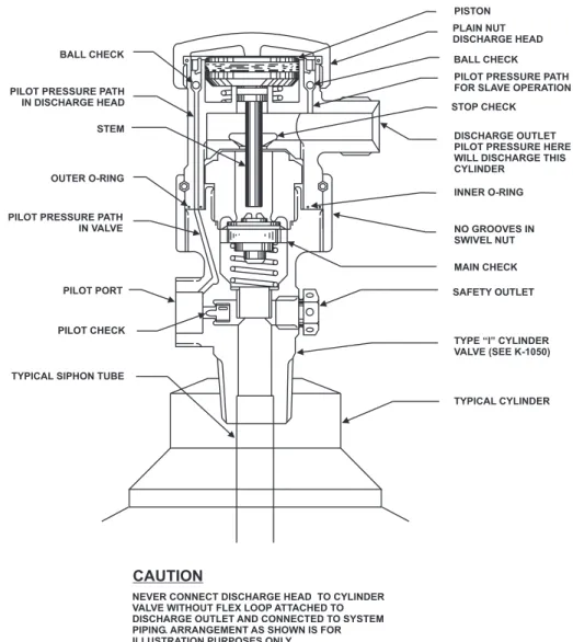
Each cylinder and valve assembly must be equipped with a discharge head at installation to actuate the cylinder valve. The discharge head is assembled to the top of the cylinder valve and contains a spring-loaded piston which when actuated by carbon dioxide pressure is designed to depress the main check in the valve and discharge the contents of the cylinder. The piston provides the necessary mechanical advantage to open the valve's main check. The discharge outlet is designed to mate with a flexible hose or swivel adapter for connection to the distribution piping. The discharge head also contains an integral stop check whose function is to automatically prevent the loss of carbon dioxide during system discharge in the event that a cylinder is removed from the distribution piping. Two different style discharge heads are available:
• Plain-nut discharge head • Grooved-nut discharge head 2-2.2.1 PLAIN-NUT DISCHARGE HEAD
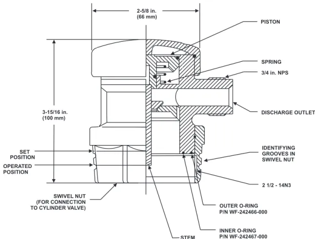
The plain-nut discharge head, Part No. WK-872450-000 (Figure 2-6), discharges the contents of the cylinder upon activation of its associated control head or upon application of pressure entering through the outlet. The plain-nut discharge head is used on each cylinder (Figure 2-7) of a multiple-cylinder system.
Figure 2-6. Discharge Head, Plain Nut
3-15/16 in. (100 mm) STOP CHECK SET POSITION OPERATED POSITION SWIVEL NUT (FOR CONNECTION TO CYLINDER VALVE) STEM INNER O-RING P/N WF-242467-000 OUTER O-RING P/N WF-242466-000 2-1/2 - 14N3 3/4 in. NPS DISCHARGE OUTLET SPRING BALL CHECK BALL RETAINER PISTON 3-13/16 in. (97 mm)
Figure 2-7. Installation of Plain Nut Discharge Head to Cylinder Valve 2-2.2.2 GROOVED-NUT DISCHARGE HEAD
The grooved-nut discharge head, Part No. 81-872442-000 (Figure 2-8), can only be actuated by a control head. Pressure entering the outlet will not actuate the cylinder. Grooved-nut discharge heads are only used for single-cylinder, or connected single cylinder main and reserve systems (Figure 2-9).
BALL CHECK PILOT PRESSURE PATH IN DISCHARGE HEAD STEM
OUTER O-RING
PILOT PRESSURE PATH IN VALVE
PILOT PORT
PILOT CHECK
TYPICAL SIPHON TUBE
PISTON PLAIN NUT DISCHARGE HEAD BALL CHECK PILOT PRESSURE PATH FOR SLAVE OPERATION STOP CHECK
DISCHARGE OUTLET PILOT PRESSURE HERE WILL DISCHARGE THIS CYLINDER INNER O-RING NO GROOVES IN SWIVEL NUT MAIN CHECK SAFETY OUTLET
TYPE “I” CYLINDER VALVE (SEE K-1050)
TYPICAL CYLINDER
NEVER CONNECT DISCHARGE HEAD TO CYLINDER VALVE WITHOUT FLEX LOOP ATTACHED TO DISCHARGE OUTLET AND CONNECTED TO SYSTEM PIPING. ARRANGEMENT AS SHOWN IS FOR ILLUSTRATION PURPOSES ONLY.