Ismo Paukamainen
Product Virtualization in Large Scale Development
Adapting System Test for a Virtualized Product
Helsinki Metropolia University of Applied Sciences Master’s Degree
Information Technology Master’s Thesis
career in the field of testing. It has, and will have, more significant impacts on testing compared to the impacts when moving from a product to another, or when moving from the waterfall model to the Agile methodology.
For me in my early fifties, making this study was a good way to upgrade my compe-tence with the network functions virtualization and related information. Writing this study helped me in the learning process, and in keeping the pace.
I am grateful to all subject matter experts and stakeholders involved in the evaluation of the outcome of my study and gave professional comments about my study. Further-more, I extend my thanks to my instructors in my company Mr Johan Kvarnström and Mr Tomas Nordman, and at Metropolia University of Applied Sciences Mr Ville Jä-äskeläinen and Ms Zinaida Grabovskaia.
I could say that my studies at Metropolia University of Applied Sciences are a demon-stration that learning is a lifetime journey.
Author(s) Title
Number of Pages Date
Ismo Paukamainen
Product Virtualization in Large Scale Development: Adapting System Test for a Virtualized Product
108 pages + 5 appendices 20 April 2015
Degree Master's Degree
Degree Programme Information Technology
Instructors
Ville Jääskeläinen, Head of Degree Program Zinaida Grabovskaia, PhL, Senior Lecturer Tomas Nordman, B.Sc. Section Manager, Johan Kvarnström, B.Sc. Product Owner
Today, the telecom operators’ networks are populated with a large variety of proprietary hardware appliances. In the near future, by using standard IT virtualization technology, many of the network equipment types will be replaced by standard servers, switches and storage. Network Functions Virtualization (NFV) is rapidly emerging in telecom networks. Virtualization will bring many changes in the software development. Testing as part of software development will also be influenced by these changes. This thesis analyzes these impacts on testing, concentrating on the system test area in particular.
The case company of this project is a leading ICT company that is also offering virtualized products for telecom markets. Many of its products have already been virtualized or this virtualization work is currently going on. This study was conducted at the Media Plane De-velopment organization of the case company.
BGF (Border Gateway Function) is a product of the case company’s Media Plane devel-opment organization, which is a logical node in the MRS (Media Resource System). The virtualization of BGF is done, as part of MRS. Virtualization of BGF means that instead of offering solutions, as a combination of proprietary software with a proprietary hardware platform only, also a combination of proprietary software with the industry standard hard-ware and softhard-ware components need to be offered. These combinations have impacts on system testing.
Thus, this study addressed the impacts brought up by virtualization in the system test area for the case organization. The analysis was twofold. First, the study analyzed the current context of the system test, which means analyzing the current system test strategy, test environment and the ways of working. The second step was to analyze how the network functions virtualization requirements impact on the current context. Based on these anal-yses the study suggests adaptations for the current system test strategy, test environment and ways of working. Finally it also presents an action plan for deploying the changes, and recommended improvements in system test strategy.
Table of Contents
Preface Abstract Table of Contents List of Figures List of TablesAbbreviations and Acronyms
1 Introduction 1
1.1 Case Company Background 1
1.2 Network Functions Virtualization 3
1.3 System Testing and Test Strategy 4
1.4 An Oncoming Change 5
1.5 Research Question, Scope and Structure of the Study 5
2 Method and Material 7
2.1 Research Approach 7
2.2 Research Design and Process 8
3 The Current Context for System Test of the Native BGF 14
3.1 The Current Product Level Test Strategy 14
3.1.1 The Current Test Scope Division 14
3.1.2 The Current Feedback Loops in Development 16
3.1.3 Release Area Concept 18
3.1.4 Feature Integration Tests 20
3.2 The Current Ways of Working 21
3.2.1 One-Track Development 21
3.2.2 High Demands on Test Automation 23
3.2.3 Continuous Integration 23
3.2.4 Testing in Teams 25
3.2.5 Test Analysis and Planning 26
3.3 The Current System Test Environment 27
3.3.1 Test Network 27
3.3.2 Test Tools 28
4.1 Concept and Overview of Network Functions Virtualization 30 4.2 Network Functions Virtualization Environment 33
4.2.1 VNF Failure Models 33
4.2.2 Complexity of the Environment 35
4.2.3 Testing Aspects Related to NFVI and Network Services 38
4.2.4 Benefits of NFV in Testing 39
4.3 ETSI NFV Virtualization Requirements Impacting System Tests 40 4.3.1 Partially or Fully Virtualized Network Functions and Portability 40
4.3.2 Performance 41
4.3.3 Resilience, Elasticity and Service Continuity 41
4.3.4 Security 42
4.3.5 Service Assurance 44
4.3.6 Operational and Management Requirements 45 4.3.7 Co-existence with the Existing Networks –Transition 48 4.4 Other Industry Specific Requirements and Recommendations 49
4.5 Software only Product 50
4.6 Summary 51
5 Impacts and Proposed Changes in System Test Strategy 53
5.1 External Factors 53
5.1.1 Integration with External Products 53
5.1.2 BUCI End-to-End Test Strategy 54
5.2 Internal Factors 55
5.2.1 Network Functions Virtualization in MRS 55
5.2.2 Ericsson Cloud System 57
5.3 Common on Most of the Testing 58
5.4 Impacts and Changes in the Release Area Concept 59
5.4.1 Release Area Upgrade and Expansions 59
5.4.2 Release Area Operations and Maintenance 60
5.4.3 Release Area Signaling 62
5.4.4 Release Area Single Traffic & Features 62
5.4.5 Release Area Media Quality 63
5.4.6 Release Area Stability 64
5.4.7 Release Area Robustness 64
5.4.8 Release Area Characteristics & In Service Performance 66
5.4.9 Release Area Vulnerability 68
5.4.10 Not Mapped Impacts 69
5.6 Impacts on Test Scope on Lower Level Tests 70
6 Impacts and Proposed Changes on Ways of Working 72
6.1 Characteristics Measurements 72
6.2 Test Automation 72
6.3 Multi-Application Continuous integration 73
6.4 Competence and Skills 73
6.5 Test Environment 74
6.5.1 Test Network 74
6.5.2 Test Tools 76
6.6 Summary 77
7 Proposed Changes and Action Plan 80
8 Evaluation of the Proposed Changes 86
8.1 Evaluation 86
8.2 Upgraded Proposal for the Changes and Action Plan 86
8.3 Summary 94
9 Opportunities for Improvements 95
9.1 Specification by Example 95
9.2 DevOps 96
9.3 Test Tools and Virtualization 98
9.4 Fault Injection 98
10 Discussion and Conclusions 99
10.1 Summary of the Study 99
10.2 Evaluation of the Study 100
10.2.1 Outcome vs. Objectives 100
10.2.2 Validity and Reliability 101
10.3 Future Steps 103
Appendices
Appendix 1. Portability of VNFs
Appendix 2. Performance Issues in the NFV Environment Appendix 3. Security Issues in Network Functions Virtualization Appendix 4. Issues in OpenStack
List of Figures
Architecture of an IMS network. Reprinted from Figure 1.
Lundström J. 2013: 6. ... 1 Decoupling applications from infrastructure. Reprinted from
Figure 2.
Ericsson 2014: 2. ... 3 Research process of this study. ... 9 Figure 3.
Agile Testing quadrants adaptation in Media Plane development. .... 15 Figure 4.
Feedback times in Media Plane Development. ... 17 Figure 5.
Radiator for all the release areas in Media Plane Development. ... 20 Figure 6.
One-Track Implementation in Media Plane Development. ... 22 Figure 7.
Principal flow of CI in Media Plane Development. ... 24 Figure 8.
The current BGF system test network environment. ... 28 Figure 9.
High-level NFV framework. Reprinted from ETSI 2014-12 a:10. ... 32 Figure 10.
Deployment Options of VNF. Modified from ETSI 2015-01a:36.. .... 34 Figure 11.
NFV Reference Architecture Framework. Modified from Figure 12.
ETSI 2014-12 a:14. ... 38 Administrative Domains. Modified from ETSI 2014-12b:22. ... 43 Figure 13.
The NFV-MANO architectural framework. Modified from Figure 14.
ETSI 2014-12 h:23. ... 47 Architecture of Virtualized MRS. Reprinted from
Figure 15.
Lundström J. 2013:3. ... 56 System Test environment for BGFv ... 75 Figure 16.
The mix of different skills of DevOps ... 97 Figure 17.
Workload classification. Reprinted from Figure 18.
ETSI 2014-06:15………..Appendix 2... 1 OpenStack Cloud Operating System. Reprinted from
Figure 19.
OpenStack (n.d.)………...Appendix 4. . 1 Agile testing quadrants. Reprinted from Gregory J. and
Figure 20.
List of Tables
Table 1. Media plane functions in MRS, Data gathered from Ericsson (n.d.b). ... 2
Table 2. Details of data collection. ... 11
Table 3. Details of validation data collection. ... 12
Table 4. Division of test scope in Media Plane Development. ... 15
Table 5. The levels and the feedback times. ... 17
Table 6. Release Areas in Media Plane Development. ... 19
Table 7. Basic Steps in the Continuous Integration. ... 24
Table 8. The working domains in NFV. Data gathered from ETSI 2014-12 a:10. ... 31
Table 9. Additional benefits when using NFV. Data gathered from ETSI 2014-10-22:3. ... 33
Table 10. The Matrix Problem by Spirent. Data gathered from Spirent 2014: 5... 37
Table 11. Potential causes of VNF failures related to NFV Infrastructure. Data gathered from Cotroneo D. et al 2014:39. ... 39
Table 12. Service continuity requirements related to Elasticity or Resiliency. Data gathered from ETSI 2013-10a:10, 11. ... 42
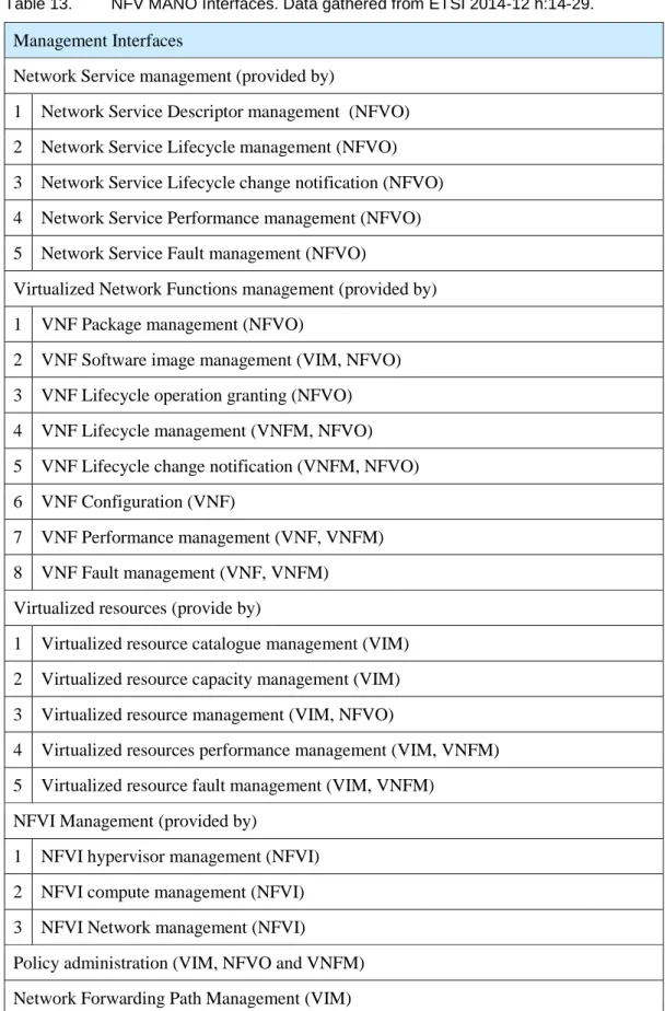
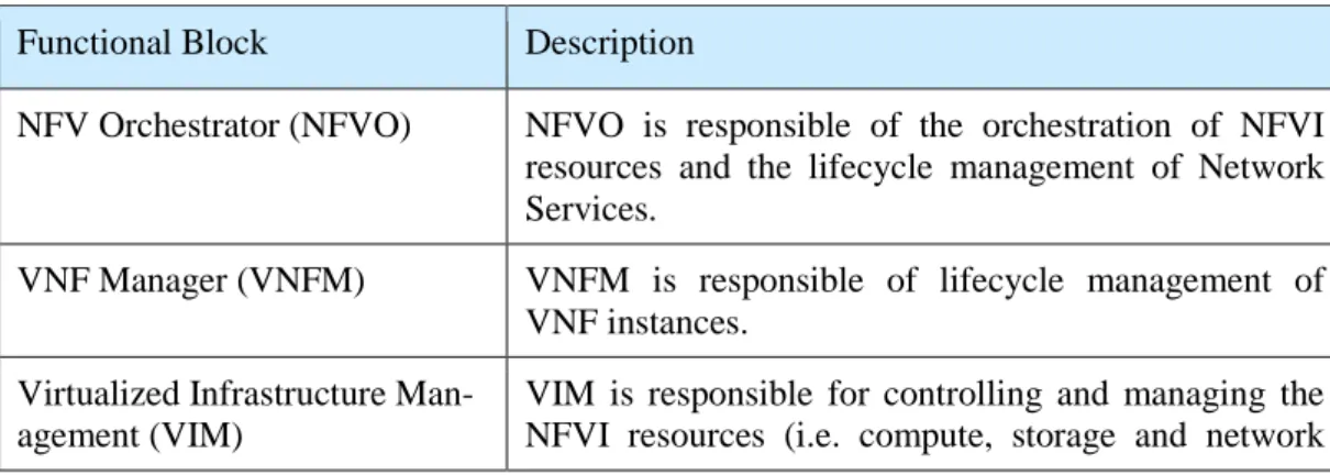
Table 13. NFV MANO Interfaces. Data gathered from ETSI 2014-12 h:14-29. 46 Table 14. Functional blocks of NFV-MANO Framework, Data gathered from ETSI 2014-12 h:25-28. ... 47
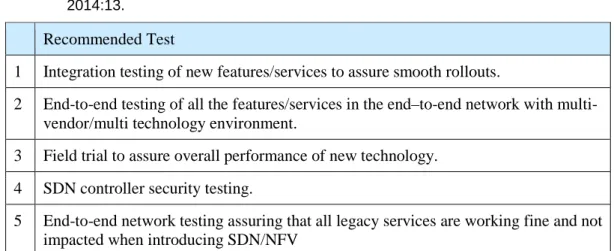
Table 15. Recommended network tests. Data gathered from Nair V. and Gupta V.K. 2014:13. ... 50
Table 16. ETSI NFV Requirements. Data gathered from ETSI 2013-10 a. ... 52
Table 17. The extent of the adaption needs in the system testing ... 77
Table 18. Proposed Changes and Action Plan ... 80
Table 19. Upgraded Proposed Changes and Action Plan ... 88
Table 20. Measurable performance metrics. Data gathered from ETSI 2014-06:51-54………..Appendix 2 .. 2
Table 21. OpenStack related resilience issues. Data gathered from Ju X. et al 2013:9-12……….Appendix 4 .. 2
Abbreviations and Acronyms
3GPP 3rd Generation Partnership Project (The 3rd Generation Part-nership Project (3GPP) unites [Six] telecommunications stand-ard development organizations (ARIB, ATIS, CCSA, ETSI, TTA, TTC), known as “Organizational Partners” and provides their members with a stable environment to produce the Reports and Specifications that define 3GPP technologies.)
AS Application Server
AAA Authentication, Authorization, and Accounting ACM Association for Computing Machinery
ANSI American National Standards Institute
API Application Programming Interface (a set of routines, protocols, and tools for building software applications)
API Application Programming Interface ATDD Acceptance Test Driven Development ATM Asynchronous Transfer Mode
BDD Behavior Driven Development BGF Border Gateway Function
BGFv Virtualized Border Gateway Function BSS Business Support System
BUCI Ericsson Business Unit Cloud and IP CEE Ericsson Cloud Execution Environment CI Continuous Integration
COTS Commercial of the Shelf CPU Central Processing Unit
CWTS Chinese Wireless Telecommunication Standard
DevOps Development and Operations. A software development method that emphasizes communication, collaboration information shar-ing, between software developers and operations professionals. DSL Digital Subscriber Line
DSP Digital Signal Processor EBS Ericsson Blade System ECS Ericsson Cloud System
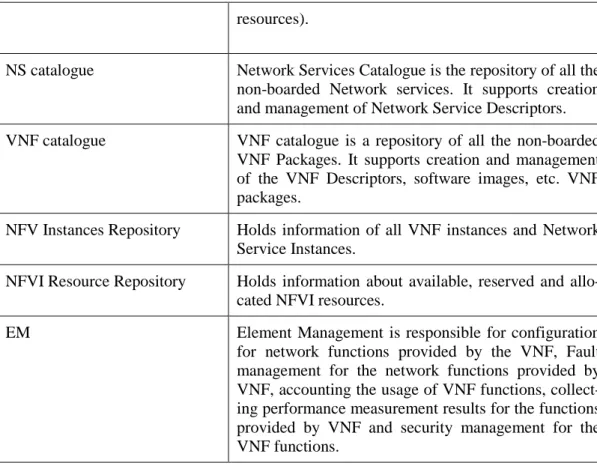
EMS Element Management System
ETSI European Technical Standards Institute FaaS Failure-as-a-Service
GCP Gateway Control Protocol HD Video High Density Video HD Voice High Density Voice
HSPA High Speed Packet data Access (HSPA) (3GPP HSPA (n.d.) IaaS Infrastructure-as-a-Service
ICT Information and communications technology IEEE Institute of Electrical and Electronics Engineers IM-MGW IP Multimedia Gateway
IMS IMS (IP Multimedia Subsystem) is a core network solution built on 3GPP standards, enabling real-time consumer and enter-prise communication services over any access technology (HSPA, LTE, Wi-Fi, Fixed). Using one core network platform, operators can offer converged mobile and fixed services over any devices. Examples of services are HD voice, voice over LTE (VoLTE), video communication, HD video conferencing, Wi-Fi calling, IP based messaging, WebRTC, and other new innovative multimedia communication services.
(Ericsson (n.d.a)) IP Internet Protocol
ISG Industry Specification Group ISP In Service Performance KVM Kernel Based Virtual Machine
L4 The Transport Layer, Open System Inter Connection (OSI), Layer 4 (ISO/IEC 7498-1 (1994:28))
L7 The Application Layer, Open System Inter Connection (OSI), Layer 7( ISO/IEC 7498-1 (1994:28))
LTE LTE (Long Term Evolution) or the E-UTRAN (Evolved Universal Terrestrial Access Network), introduced in 3GPP R8, is the ac-cess part of the Evolved Packet System (EPS). The main re-quirements for the new access network are high spectral effi-ciency, high peak data rates, short round trip time as well as flexibility in frequency and bandwidth (3GPP LTE (n.d.)).
MANO Management and Orchestration M&O Management and Orchestration
MGC Media Gateway Controller
MMTel AS Multi Media Telephony Application Server MRF Media Resource Function
MRFP Multimedia Resource Function Processor is a media plane node in MRS used to mix, source or process media streams for voice and video conferencing, multimedia message playing and me-dia conversion services.
MRS Media Resource System, which provides the converged media plane functionality in IMS networks.
MSC-S Mobile Switching Center Server, MSC Server MSC Mobile Switching Center
MSS Mobile Soft Switch
MTAS Multimedia Telephony Application Server N-PoP Network Point of Presence
NFV Network Functions Virtualization NFV-MANO NFV Management and Orchestration NFVO NFV Orchestration
NIC Network Interface Controller O&M Operations and Maintenance OS Operating System
OSS Operations Support System OVF Open Virtualization Format
PL Payload
PNF Physical Network Function
PRA Preliminary Availability. The product is ready for release with limited availability.
PSTN Public Switched Telephone Network QoE Quality of Experience
QoS Quality of Service
RX Reception
SBG Session Border Gateway SC System Controller
SGC Session Gateway Controller
SGCv Virtualized Session Gateway Controller SGW Signaling Gateway
SIP Session Initiation Protocol SLA Service Level Agreement SUT System Under Test
TTC Telecom Technology Committee, TTC is an incorporated asso-ciation that contributes to standardization activities in the field of information and communication technology (ICT) by developing and disseminating standards for information and communica-tions networks.(TTC(n.d.))
TTCN-3 Testing and Test Control Notation version 3
TX Transmission
VIM Virtualized Infrastructure Manager VM Virtual Machine
VNF Virtual Network Function
VNFM Virtual Network Function Management VoLTE Voice over LTE
WebRTC Web Real Time Communication
Wi-Fi Commercial term for WLAN (wireless local area network), an abbreviation for Wireless Fidelity
1
Introduction
Network Functions Virtualization (NFV) is a trend in today’s telecom business. It has impacted and will impact on the development of the telecom systems in many ways. This study focuses on exploring the impact of virtualization on sys-tem testing in the context of one department of the case company.
1.1 Case Company Background
The case company of this project is Ericsson. It is a leading ICT company that offers products for telecom markets. Many of the Ericsson products have already been virtualized or the virtualization is going on. For Ericsson products virtualiza-tion means that it should offer, in addivirtualiza-tion to soluvirtualiza-tions based only on Ericsson proprietary software with the proprietary hardware platform, also a combination of proprietary software with the industry standard hardware and software compo-nents.
One example of product virtualization is the IMS network. The architecture of the cloud platforms based IMS network is illustrated in the figure below (Figure 1):
Figure 1 above shows the network architecture that is build optimizing latency and ensuring bandwidth efficiency.
Ericsson IMS (IP Multimedia Subsystem) is core network solutions build on 3GPP standards. It is meant for real-time communication services over mobile and fixed access technologies such as HSPA, LTE, Wi-Fi, and DSL. Examples of these communication services are HD (High Definition) voice, voice over LTE (VoLTE), video communication, HD video conferencing, IP based messaging, Wi-Fi calling and WebRTC. (Ericsson n.d.a)
The converged media plane functionality in IMS networks are provided by Media Resource System (MRS). Media Resource System contains the media plane functions for IMS networks listed in the table below (Table 1):
Table 1. Media plane functions in MRS, Data gathered from Ericsson (n.d.b). Media Plane Function
1 The Border Gateway Function (BGF) provides the security and policy control for the media plane between IMS core network and access network
2 The Multimedia Resource Function Processor (MRFP) provides media services in IMS networks such as announcements, audio and video conferencing and media processing
3 The IP Multimedia Gateway (IM-MGW) is a connectivity layer function for IMS - PSTN network interconnection
Table 1 above lists the Media Plane functions in MRS for IMS networks. MRS can be deployed as combined node or with any combination of these logical nodes (Ericsson n.d.b).
Border Gateway Function (BGF) is a logical node in the Media Resource System. BGF is a product of the case company’s Media Plane development organization. This study, therefore discusses how the BGF node is virtualized, as part of MRS, for the cloud platforms based IMS.
1.2 Network Functions Virtualization
Network Functions Virtualization is actively gaining ground in telecom industry. It will leverage modern technologies such as those developed for cloud computing, like for example, hardware virtualization by means of hypervisors, as well as, the usage of virtual Ethernet switches for connecting traffic between virtual machines and physical interfaces. The hardware used for this are industry standard high volume servers (e.g. using x86 architecture) and components, such as network Interface controllers (NIC). The software components are, for example, Intel Da-ta Plane Development Kit, open API’s for management and daDa-ta plane control, such as OpenStack or OpenFlow.
Network Functions Virtualization aims for a clear separation between functional logic defined in software and the underlying infrastructure, offering an opportunity to redesign the way network functions are implemented. Instead of being imple-mented in vertically integrated boxes (often called “physical appliances,”) network functions will be provided as virtual appliances, in other words, software is exe-cuted in a virtualized infrastructure environment. This is shown in the figure below (Figure 2):
Decoupling applications from infrastructure. Reprinted from Ericsson 2014: 2. Figure 2.
Figure 2 above illustrates how Network Functions Virtualization (NFV) decouples applications, for example, Virtual Network functions (VNF), from the infrastruc-ture. (Ericsson 2014: 2)
1.3 System Testing and Test Strategy
A term System Testing is defined in the following way: “In system testing the be-havior of whole system/product is tested as defined by the scope of the develop-ment project or product. System testing should investigate both functional and non-functional requirements of the testing.” (ISTQB n.d.) A functional requirement is a requirement that specifies new functionality, whereas a non-functional re-quirement is a rere-quirement that specifies criteria that can be used to judge the operation of a system, rather than specific behaviors (ISO/IEC/IEEE 29119 n.d. a:29).
In the context of this study, a term Test Strategy, wherever used in the text, means the organizational test strategy as described in ISO/IEEE 29119 Software Testing standard (ISO/IEC/IEEE 29119 n.d. b:2,5,8,9,11,12). The organizational test strategy defines, for example, how the test scope, is divided between differ-ent activities in the organization, who is responsible of doing what. It may contain information about, guidelines or directives for working, for example, what docu-ments are required to produce, when to make defect reports, or test reports. It may include also a strategy for test tools, defining the main tools that should be used in testing.
The organizational test strategy is often divided in two parts, one concerning the near future (typically around e.g. 1-3 years ahead) and the other part concerning the future with a longer perspective (typically for e.g. 5 years ahead). Since the organizational test strategy also serves for communication goals and ways of working, it means, it needs to be well documented and available, especially in the multi-site organization. Therefore it is important to make sure that everyone in the organization knows where to find it, what it contains.
1.4 An Oncoming Change
In the case company, like in many other telecom vendors, the virtualization means a huge change for the whole product development, including testing. The biggest impacts on testing will be in the test strategy, test environment in the tar-geted hardware, test tools and the ways of working. Therefore starting the virtual-ization will require starting with defining a new strategy and approach for testing. Today the Media Plane organization has been developing Border Gateway Func-tion (BGF) product already for years, and its specified test strategy has been working well. Therefore, the current test strategy can be used as a starting point for the new strategy. However, to be able to set up a new strategy and approach for testing, all the impacts on testing from virtualization should be analyzed in advance. In practice this analysis and anticipation should cover the test environ-ment, test tools, the ways of working and human aspects, such as, new skills and competencies of testers.
1.5 Research Question, Scope and Structure of the Study
The objective of this study was to develop such a system testing strategy that address the change related to the forthcoming virtualization of BGF product in product development. To put precisely, this study answered the following re-search question:
How to adapt the current system testing for the virtualized border gateway function (BGFv)?
This included addressing the following sub-questions:
1. To clarify what are the requirements for the virtualization
2. To clarify how the virtualized border gateway function (BGFv) operates. 3. To clarify how system testing need to be changed for this new virtualized
environment
4. To adapt the present system test strategy for the new virtualized border gateway function (BGF)
5. To evaluate the proposed changes in strategy validated by the key ex-perts/ stakeholders in Media Plane Development.
This study includes analysis of the Network Functions Virtualization requirements and material related to it, and how they impact system testing in the case compa-ny’s Media Plane Development organization. Based on this analysis, proposed changes in system test strategy, triggered by the impacts are presented. The thesis was concluded by the evaluation of the proposed changes in the system test strategy, which is done by the expertise of the experts.
This report is written in ten sections. Section 2 describes the methods and the material used for this study. Section 3 describes the most important factors in the current context of the system test that help the reader to understand the needs of the change. Such important factors are, for example, ways of working, overall test strategy of the product, the importance of the feedback loops and the test envi-ronments. Section 4 describes the network functions virtualization, the require-ments it has, and the network functions virtualization environment in general. Based on Sections 3 and 4, Section 5 and 6 present the impacts of the Network Functions Virtualization on the case company’s system testing, and also propose changes in system test strategy for adapting these impacts. Section 7 presents a detailed action plan for the changes proposed in the previous sections. Section 8 evaluates the proposal validating it by the key experts/stakeholders in Media Plane Development organization. Based on the evaluation it also presents the upgraded plan for deployment. Section 9 introduces opportunities for improve-ments, and finally Section 10 concludes the study by summarizing and evaluating it.
2
Method and Material
This section discusses the research approach, research design and methods used in this study. It gives an overview about the data and data collection meth-ods and analysis used.
2.1 Research Approach
To achieve the research goals and to contribute to solving the research problem, this study was conducted using an exploratory case study approach. This ap-proach was selected as the most suitable for addressing the research question and the objective discussed in the Introduction.
According to Baxter P. and Jack S. (2008) the quantitative case study methodol-ogy should be considered when the focus of the study is to answer ‘how’ and ‘why’ questions and the study is aiming to cover contextual conditions. In this study the analysis of the current system test formed the case that needed to be studied. Then Baxter P. and Jack S. (2008) also instruct that after deciding to use a case study approach the case of analysis need to be determined. That is, to decide what is the unit of analysis, in a bounded context. In this study it was the system test in Media Plane Development organization. After determining what the case is, it needs to be considered what will not be included in the case. In order to avoid the problem having too many objectives in the study Baxter P. and Jack S. (2008) suggested that placing boundaries on the case that can prevent the study from losing its focus. This would mean binding a case to time and place, time and activity, and by definition the case and its context. In this study, the case thus meant analyzing the current system test in Media Plane Development organ-ization, with the focus on the current (time) system test (activity and context) in Media Plane Development organization (place and context).
According to Baxter P. and Jack S. (2008), once the qualitative case study is se-lected as an approach for the research, the case and its boundaries have been determined, the type of the case study need to be considered. The case study may be categorized as explanatory, exploratory, or descriptive. In this study, to analyze the current system test in the Media Plane Development organization was exploratory in its type.
2.2 Research Design and Process
The research designed of this study includes the following steps. First, the litera-ture review was conducted for identifying theoretical knowledge about the net-work functions virtualization. Second, the study analyzed the current situation in the case company’s Media Plane Development organization, which made the case of this study. Third, the solution was suggested based on the above two. Finally, the solution was validated with the key stakeholders and case company experts for gathering feedback and further improvement suggestions. The re-search process is presented in the figure below (Figure 3):
Research process of this study. Figure 3.
Figure 3 above shows the research process with all the stages. These stages are detailed in the flowing sections.
Literature Review
The study started with a literature review on virtualization and its impacts. Litera-ture review was done by identifying, evaluating and interpreting the existing knowledge relevant to this study. It was based on the analysis of publically avail-able scientific articles (including publicly availavail-able Ericsson articles), books and other resources relevant to this study area.
To the search for the existing knowledge and best practice, the relevant literature database sources were used, such as ACM digital library, IEEE Xplore® Digital Library and ETSI Technologies & Clusters, but not limiting the search within the above mentioned databases only. Various sources, articles, journals, white pa-pers were found. Most of the sources were found by using key words including, for example, ‘network functions virtualization’, ‘NFV’, ‘telecom cloud’.
Additionally, general information about the virtualization of telecom systems was found from ETSI (European Technical Standards Institute). There is a network operator-led Industry Specification Group (ISG) with open membership working through the technical challenges for Network Functions Virtualization. ETSI NFV SG has published several documents related to Network Functions Virtualization (ETSI 2014-10-22 :3, 4). These ETSI documents give a comprehensive view on what kind of expectations and requirements do network operators have.
In addition to publically available material also the case company’s internal infor-mation about the implementation of the virtualized Border Gateway Function (BGFv) and the virtualized Media Resource System MRS needed to be analyzed to see how the implementations impact the system testing.
It should be noted that it was challenging to find information outside the company related to working methods or strategies related to test and virtualization. With this area being fairly topical at the moment, that kind of information is seen as business sensitive and thus not public. Therefore, the information for the analysis from other case company organizations was considered highly valuable and could not be abundant when it came to impacts on testing.
The Current State Analysis
Second, the study analyzed the current situation in the case company’s Media Plane Development organization, which made the case of this study. The analy-sis concentrated on how the virtualization impacts the system test and it was based both on the literature findings and the observations, interviews, and case company document scrutiny as the case study.
The current state analysis was based on the data listed in the table below (Table 2.) collected and analyzed in the case company:
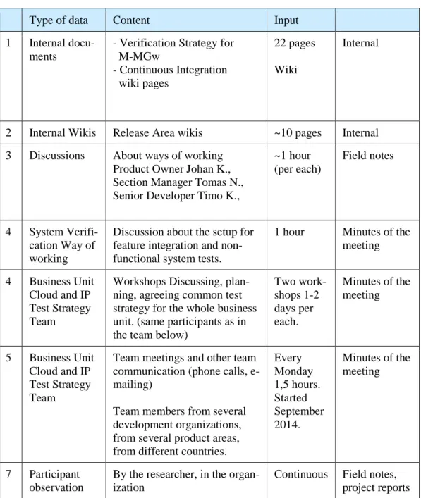
Table 2. Details of data collection.
Type of data Content Input
1 Internal docu-ments
- Verification Strategy for M-MGw - Continuous Integration wiki pages 22 pages Wiki Internal
2 Internal Wikis Release Area wikis ~10 pages Internal
3 Discussions About ways of working
Product Owner Johan K., Section Manager Tomas N., Senior Developer Timo K.,
~1 hour (per each) Field notes 4 System Verifi-cation Way of working
Discussion about the setup for feature integration and non-functional system tests.
1 hour Minutes of the
meeting
4 Business Unit Cloud and IP Test Strategy Team
Workshops Discussing, plan-ning, agreeing common test strategy for the whole business unit. (same participants as in the team below)
Two work-shops 1-2 days per each. Minutes of the meeting 5 Business Unit Cloud and IP Test Strategy Team
Team meetings and other team communication (phone calls, e-mailing)
Team members from several development organizations, from several product areas, from different countries.
Every Monday 1,5 hours. Started September 2014. Minutes of the meeting 7 Participant observation
By the researcher, in the organ-ization
Continuous Field notes, project reports
As seen from the table above, the current state analysis focused on the current situation in the Media Plane Development organization. It was analyzed based on the documentation, interviews and workshops. This included meetings, discus-sions and e-mailing with people from other Ericsson organizations that were in the same situation, or who had already got further in virtualization.
Impact Analysis
Third, based on the input collected in the literature review and from the current state analysis, the impacts on system testing in Media Plane Development were analyzed. This happened by analyzing how feasible the current system testing was for new virtualization requirements. In practice this meant analyzing needs for changes in system test strategy, such as, changes in the test scope, changes test environment or ways of working.
Proposal Building and Evaluation
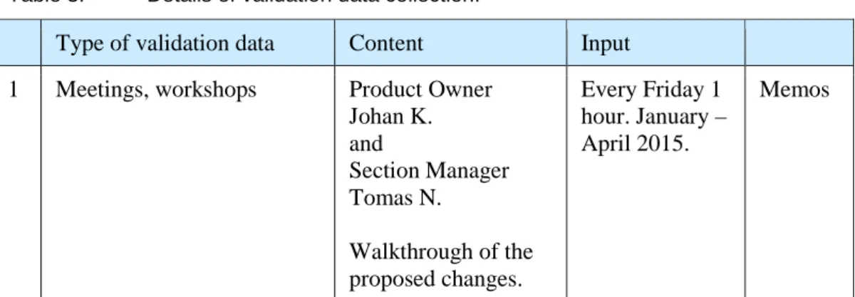
Fourth, based on the impact analysis, the study proposed changes in system test strategy, an action plan for implementation of the new system test strategy, and recommended improvements. Fifth, as a method of evaluation of the proposed model, together with the result of the impact analysis, the study validated the proposal in the validation sessions with key stakeholders and experts in the case organization. At the same time, also the results of the impact analysis were eval-uated. The evaluation was based on the interviews and workshops (validation sessions) as listed in the table below (Table 3.):
Table 3. Details of validation data collection.
Type of validation data Content Input
1 Meetings, workshops Product Owner
Johan K. and Section Manager Tomas N. Walkthrough of the proposed changes. Every Friday 1 hour. January – April 2015. Memos
2 Evaluation of the proposed changes Experienced Devel-oper Marko S. Evaluation of the area. RA Media Quality e-mails Senior Developer Joona V. Evaluation of the area. RA Vulnerabil-ity e-mails Master Developer Rabbe T. Evaluation of the area. RA Character-istics & ISP
e-mails
Product Owner Mik-ko P. Evaluation of the area. RA O&M, RA Upgrade and Expansions e-mails
Product Owner Johan K. Evaluation of the area. RA Robustness, RA Stability RA Signaling RA Single Traffic & Fea-tures e-mails Test Environment Manager Antti A. Evaluation of the area. Test Environ-ment e-mails
3 Overall evaluation of the study Section Manager Juha K. and Section Manager Tomas N. Overall Evaluation
General view e-mails
Head Product Owner Tatu K.
and
Strategic Product Manager Johan L.
Overall Evaluation
3
The Current Context for System Test of the Native BGF
This section describes the current context of the system test for the native Border Gateway Function (BGF) product on a level that gives a general overview and helps to understand the needs for changes when the product is virtualized. Also two ‘internal factors’ in the current development in the Media Plane Development organization are presented. First, fitting system testing in Agile context by using a release area concept. Second, using the one-track development, that is an ena-bler for continuous deliveries.
3.1 The Current Product Level Test Strategy
Presently, the Media Plane Development is using a test strategy that covers all software testing activities in product development. This means that, also system test strategy is part of it. There are two types of system tests, functional and non-functional system tests. The first is covered by end-to-en feature integration tests, and the latter is covered by the release area concept. Release Area Concept is presented later in Section 3.1.3 Release Area Concept. And Feature integration tests are presented in Section 3.1.4 Feature Integration. Originally the strategy was created 2009 when the organization moved from incremental software de-velopment to using the Agile software dede-velopment methodology. The strategy has evolved during the years based on the feedback from its usage and it has been continuously improved.
As said, the current test strategy covers all testing in the software development in Media Plane Development organization. That is, all test levels starting from the unit level up to network level. This kind of overall test strategy is crucial in a communication point of view. It describes the test scope on each test activity/test level, thus everyone knows what is tested and verified and where, on which activ-ity. Overall strategy helps to plan testing so that nothing is omitted, but also in a way that there is no unnecessary and costly overlapping in testing.
3.1.1 The Current Test Scope Division
The existing test strategy corresponds to the agile methods. The Media Plane Development adaptation of the Agile Testing Quadrants is shown in the figure
below (Figure 4). It is based on the Agile Testing Quadrants presented by Lisa Crispin and Janet Gregory (Gregory J. and Crispin L. 2009: 98).
Agile Testing quadrants adaptation in Media Plane development. Figure 4.
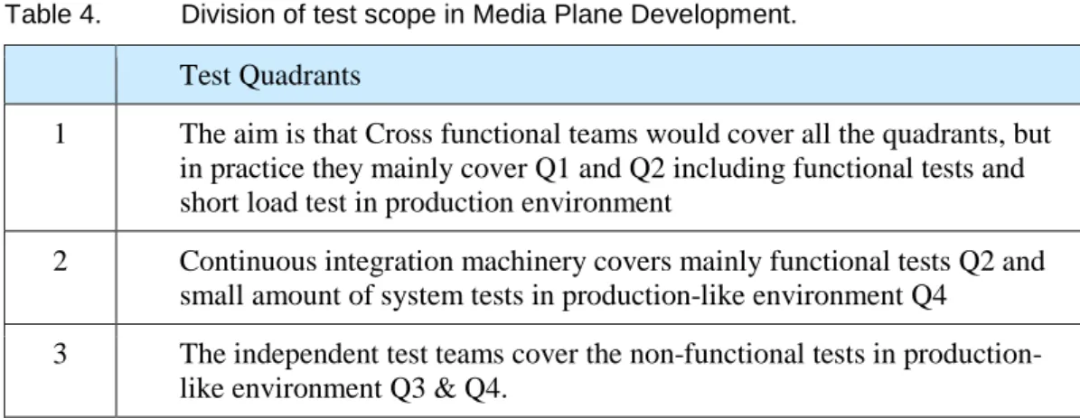
Figure 4 above illustrates a model of Agile Testing Quadrants used in Media Plane Development. This model defines on a high-level all the tests that are needed. The model helps to communicate the test needs to everybody. The tests in Media Plane Development organization are divided in the ways illustrated in the table below (Table 4.):
Table 4. Division of test scope in Media Plane Development. Test Quadrants
1 The aim is that Cross functional teams would cover all the quadrants, but in practice they mainly cover Q1 and Q2 including functional tests and short load test in production environment
2 Continuous integration machinery covers mainly functional tests Q2 and small amount of system tests in production-like environment Q4
3 The independent test teams cover the non-functional tests in production-like environment Q3 & Q4.
The division of the testing quadrants between the teams is shown in Table 4 above. After these tests in the Media Plane Development there is currently IMS network Integration and Verification activity that performs, as the name says,
network level tests for the whole IMS release. As part of the IMS network also BGF releases are delivered to these tests. The team setup and activities are dis-cussed in more details in the following sections.
3.1.2 The Current Feedback Loops in Development
Fast feedback loops is one of the basic idea in the strategy. That is, the time measured from implementing a new program code to getting a feedback about the quality should be, as short as possible. The feedback tells if the newly imple-mented code worked, as it should, and if it caused any problems in the previous legacy functionality. To be able to get fast feedback means in many cases that testing is reasonable to perform in the target, production-like, test environment. To get fast feedback, tests need to be implemented and executed on the integra-tion level, which provides shorter preparaintegra-tion and execuintegra-tion time. Not forgetting that test code implementation requires time and resources, and creates always also maintenance costs. In general test automation is one way to shorten the feedback loop, especially when it comes to legacy part of the system.
When working in Agile context the development is typically done in a small in-crements, e.g. in two week’s sprints as it is currently done in the case organiza-tion. That is, why it is very important that the developers get the feedback of their work as fast as possible to be able to make corrections also as fast as possible. There is a concept for fast feedback in the Media Plane development organiza-tion. It is called 4F-concept. It stands for “Fail-Fast-Fix-Fast”. The figure below (Figure 5) shows the approximate feedback times of the current testing on differ-ent integration levels in Media Plane Developmdiffer-ent.
Feedback times in Media Plane Development. Figure 5.
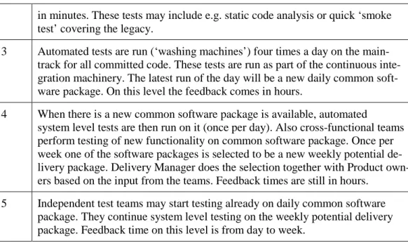
Figure 5 above shows the feedback times, from seconds to week. To give further details the table below (Table 5.) shows different levels and feedback times in the current development:
Table 5. The levels and the feedback times. Floor Feedback Times per Activity
1 Work is done on various local software versions. Developers test their own code. The feedback of the quality is possible in very short time, even in seconds. 2 Cross Functional Teams may have their own team versions, but they
are supposed to commit to main-track continuously after ‘team tests and static analyses’. In team tests the feedback times is in minutes. Tests, which are done on teams own build before committing on the main-track must provide feedback
in minutes. These tests may include e.g. static code analysis or quick ‘smoke test’ covering the legacy.
3 Automated tests are run (‘washing machines’) four times a day on the main-track for all committed code. These tests are run as part of the continuous inte-gration machinery. The latest run of the day will be a new daily common soft-ware package. On this level the feedback comes in hours.
4 When there is a new common software package is available, automated system level tests are then run on it (once per day). Also cross-functional teams perform testing of new functionality on common software package. Once per week one of the software packages is selected to be a new weekly potential de-livery package. Dede-livery Manager does the selection together with Product own-ers based on the input from the teams. Feedback times are still in hours.
5 Independent test teams may start testing already on daily common software package. They continue system level testing on the weekly potential delivery package. Feedback time on this level is from day to week.
Table 5 above explains the levels in the pyramid figure (Figure 5.) starting from the first floor of the pyramid. These feedback times are also used when selecting the test environment (i.e. when selecting the integration level) for tests. When selecting the environment, it needs to be considered what is sufficient environ-ment for covering the test scope, and also capable to provide the fastest feed-back, containing also the time used for preparations and implementing possible test program code.
3.1.3 Release Area Concept
Before Media Plane Development organization moved to agile, the system test was a separate test phase. It was a very late activity with a long lead-time. When moving to agile, it was clear that this kind of phase did not fit in the picture any-more. On the other hand, the fact is that a big number of faults, found in the pro-duction at the customer’s sites, are in the system legacy such as in stability or robustness, not in the new features. The reason behind this is that the new fea-tures are very well in focus when they are developed, whereas the system legacy as an area is so wide that it could not be covered fully.
Although the system test phase was not feasible anymore, the system legacy needed to be secured somehow. The former system test phase needed to re-place by something else, which was more feasible for agile ways of working. The solution was that Media Plane Development moved from the system test phase
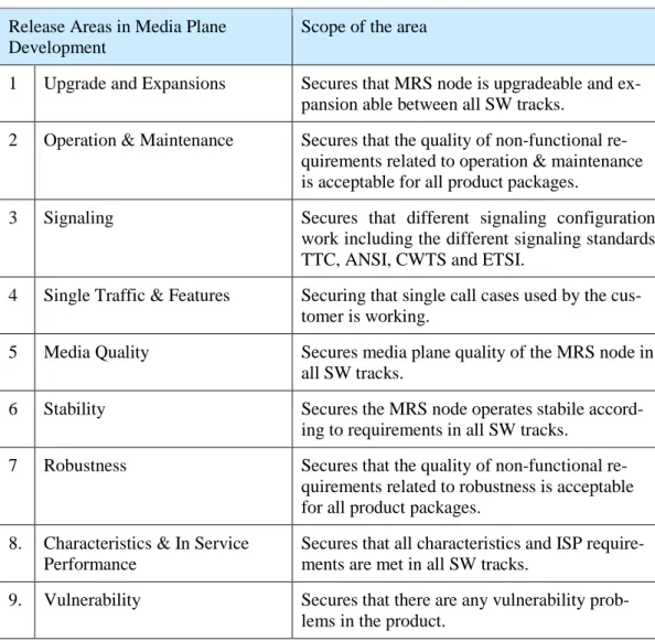
to continuous assurance of the system quality. Setting up Release Areas did this. Release areas cover the system legacy. That is, they cover non-functional re-quirements, which specify criteria that can be used to judge the operation of a system, rather than specific behaviors. The operations related to these require-ments can be categorized representing groups such as characteristics, robust-ness, upgrade, security, quality of service, and stability of the system. This group-ing is a base for the release areas. As said, the implementation in Media Plane Development for non-functional tests was a release area concept containing the release areas listed in the table below (Table 6.).
Table 6. Release Areas in Media Plane Development. Release Areas in Media Plane
Development
Scope of the area
1 Upgrade and Expansions Secures that MRS node is upgradeable and
ex-pansion able between all SW tracks.
2 Operation & Maintenance Secures that the quality of non-functional re-quirements related to operation & maintenance is acceptable for all product packages.
3 Signaling Secures that different signaling configuration
work including the different signaling standards TTC, ANSI, CWTS and ETSI.
4 Single Traffic & Features Securing that single call cases used by the cus-tomer is working.
5 Media Quality Secures media plane quality of the MRS node in
all SW tracks.
6 Stability Secures the MRS node operates stabile
accord-ing to requirements in all SW tracks.
7 Robustness Secures that the quality of non-functional
re-quirements related to robustness is acceptable for all product packages.
8. Characteristics & In Service Performance
Secures that all characteristics and ISP require-ments are met in all SW tracks.
9. Vulnerability Secures that there are any vulnerability
prob-lems in the product.
The independent test teams perform the tests in the release areas listed in the Table 6. Testing is performed on potentially deliverable software (weekly) pack-ages (sometimes also on the daily common software package) providing
continu-ous feedback of the system quality. The Feedback is provided from all the re-lease areas by using the radiators, as shown in the figure below (Figure 6):
Radiator for all the release areas in Media Plane Development. Figure 6.
Figure 6 above illustrates an example how does the radiator look like for a soft-ware package, here Node Delivery Package 6.6.0.0. V01. Each of the release areas may be either red or green. The color depends if the quality is sufficient for a release, or not. The independent test team, that is responsible of the corre-sponding release area, will set the color based on the results of their tests. This radiator view is made visible to all employees working in Media Plane Develop-ment by showing it in the TV screens on the corridors and rooms where the teams are sitting.
3.1.4 Feature Integration Tests
Where the Release Area concept covers non-functional requirements of the sys-tem, the Feature Integration covers integration of new features in the system. In other words, it covers the functional requirements. Feature integration is done in Network Environment equipped with the controlling nodes Session Border Gate-way (SBG) and Mobile Switching Server (MSC). Part of it is end-to-end network integration testing, which means that it is performed with real end-to-end clients. Feature integration tests contribute also to release areas Stability and
Robust-ness. This happens by performing short network level load test and some robust-ness type of tests, like for example, restarts while integrating new features on the network level.
3.2 The Current Ways of Working
Presently, the Media Plane Development is using Agile methodology as its main method of working. It has been used since year 2009. There are so-called cross-functional development teams working in three countries (Finland, Hungary and United States). In addition to that, there are also independent test teams support-ing cross-functional teams in system test area, both in functional and non-functional system tests.
The current way of working is built around the following principles: a) one-track development, b) test automation, c) continuous integration, c) testing in cross-functional and independent test teams, d) a proper test analysis and planning. They are described in more detail below.
3.2.1 One-Track Development
Using One-Track method in the development means that all the development is done on the main-track. Cross-functional teams commit their newly made code in the main-track (i.e. main-branch) several times per day. After that all the testing is performed in the main-track. The principles of the one-track development are illustrated in the figure (Figure 7) below:
One-Track Implementation in Media Plane Development. Figure 7.
Figure 7 above shows, that the One-Track means exactly one track only, from the development point of view. For releases a parallel release-track is created, but that is only for testing purposes. The release-track is a snapshot of the main-track on certain time.
The dots in Figure 6 are defined in the following ways. First, the red dots in the main-track mean that the quality is not acceptable on all of the release areas (see Section 3.1.3). That is, the product quality is not sufficient for a release. Second, the blue dots are “snapshots” of the main-track software. It means that the final compile has been made and no changes in SW are possible anymore in the re-lease-track. This parallel release-track is only for testing. The date/week when the release-track is made is dynamic. It’s more effective to fix the code in the main-track and take a new snapshot than fixing the defect in both the main and the release-track (Otherwise in practice it would mean “two tracks” open also for development all the time. Now the extra track is limited on test activities only.) Finally, the black dots mark the stage when the release is made. In practice it means that the developed SW is put on the SW gateway and is accessible to all the customers
One-track development is an enabler for the continuous deliveries and it is a way to save in maintenance costs. So far, the benefits from One-Track development for Media Plane Development have been: 1) the possibility to release SW pack-age once per week if needed, 2) the correction mapping (of defects) between
releases is minimized, and 3) the number of supported upgrade paths is much smaller than it used to be.
3.2.2 High Demands on Test Automation
In Agile ways of working the new features are developed in frequent time periods, in sprints. A sprint in the Media Plane Development is two weeks. Within these sprints development teams commit their new software once per day, even more often. The teams should get fast feedback after every commit about the quality of the software. That is, information about the quality of both their new code, and the quality of the legacy functionality. Quality of the legacy means that the func-tionality that has worked in the earlier deliveries, should still work properly. This requires frequent and fast regression test execution. Frequent regression testing requires test automation.
High automation rate of tests is a key in an Agile development. In Media Plane Development tests are automated whenever it is feasible, and what is more im-portant, whenever there is a business case for automation. The most fertile area for test automation is in regression testing, where the same tests are repeated frequently. Business case thinking includes the maintenance costs of the auto-mated cases.
3.2.3 Continuous Integration
Continuous integration (CI) in Media Plane Development provides a fast, auto-mated, feedback about the quality of the developed software. One of the main rules in the Agile development is: “Do not break the legacy”. That is why the Con-tinuous integration in Media Plane Development focuses on the legacy part of the product. The continuous integration cycle is repeated several times per day; therefore it needs to be automated.
In Media Plane Development the continuous integration machinery is fully auto-mated. The principal flow of it is illustrated in the figure below (Figure 8):
Principal flow of CI in Media Plane Development. Figure 8.
Figure 8 above shows the principal Continuous Integration (CI) flow that is built around the steps listed in the table below (Table 7.). Radiator displays are used to visualize build and test results.
Table 7. Basic Steps in the Continuous Integration. Steps Action
1 Checking-in, committing new source file content into version control system 2 Compiling new source code into target binaries
3 Building an installable upgrade package from new version of target binaries 4 Upgrading the test node with the newly created package
5 Executing test campaign on new software, to verify its legacy and newly add-ed functionality working
Table 7 shows the steps in the automated Continuous Integration (CI) cycle in Media Plane development. The first step is a "human interaction" and the upcom-ing steps are automatically initiated after each other. The first step is the most important step in the process. If this has not taken, there is nothing to build, inte-grate or test, nothing continuous. Thus, frequent commitments must be part of the working culture. In other words, developers should commit a newly imple-mented code frequently.
To explain the flow in more detail, CI Automation is continuously polling for com-mits. Commit triggers target build, which is followed by creation of an upgrade package. The upgrade package is then installed in to the production-like test en-vironment where automated tests are run. This is repeated four times per day on the main-track for all committed code. The tests in CI cover functional tests; short stability and also some selected non-functional system test cases. The functional test cases used in the automated test runs, are made by the cross functional teams. They have stored the tests (i.e. test suites) in the source control reposito-ry. A selection of all functional test cases is marked with specific tags, and test automation in continuous integration machinery executes these cases directly from the repository.
The latest run of the day will make a new common software package. Teams will perform functional tests on this package. The automated system level tests are run once per day on this daily common software package. Once a week, one of the daily packages is selected to be a weekly package (that is also a potential delivery package). Independent test teams perform their tests on this weekly package, but they are also often asked/allowed to take daily package e.g. in a case of platform changes. This is to get fast feedback about the changes. 3.2.4 Testing in Teams
Agile methodology suggests that all the testing should be performed by the de-velopment teams, cross-functional teams. In an ideal case this would work, but in scale software development project this is not always the case. In large-scale software development, there might be time constraints, competence and cost efficiency issues that prevents of doing this. This is also the case in the Me-dia Plane development, where in practice; the scope of the testing in is divided between 1) cross-functional teams and 2) independent test teams.
First, in cross-functional teams, testing covers tests that gives fast feedback to teams themselves. This contains lower level tests, such as unit and component tests in development environment, and also system level functional testing includ-ing possible some load tests. System level functional tests are executed in the
perform non-functional and functional testing (including integration aspects) in the network test environment. The functional testing focuses on the integration of the new features, whereas, the non-functional tests contain, for example, robustness tests, stability tests and characteristics tests. These non-functional tests were covered by Release Area concept (as described in Section 3.1.3).
The reason for having such independent test teams is that, otherwise these tests would belong to test scope of all or at least many cross-functional teams. In prac-tice this would mean that each and every team should have network test envi-ronment with system testing specific tools, such as, load generators. This would then mean that all teams should have also in many cases specific competence to perform these tests. All this is very expensive and even impossible when it comes to the competence. Everyone cannot be a specialist in everything. This is why the current test environments, test tools and competencies are concentrated in inde-pendent test teams specialized on their own areas.
3.2.5 Test Analysis and Planning
Test analysis and planning are in a centric role in large-scale development. When there are many teams working for the same product, it is important that the test-ing is planned well to avoid overlapptest-ing testtest-ing and also that anythtest-ing will not be omitted. Basis for planning is test analysis. It will make impacts on testing visible on time, such an impact is, for example, a need for a new testing tool, because of the new feature or other requirement. This kind of impacts need to be recognized as early as possible, since it may take several months to get the needed tool into the use. The current test analysis and test planning work is implemented in the Media Plane Development as described on high level in the following.
Presently test analysis is done mainly in two activities. First, high level test analy-sis is done in the Early Phase Program, where the test analyanaly-sis results in high-level information about the impacts on testing caused by the development of the new feature. This includes impacts on test tools and test environment. It covers also the cost estimation, hardware forecast, effort and lead time estimates. This analysis may be triggered by various sources, but usually the Product Manage-ment does it. The analysis outcome is then included in the one-pager of the fea-ture, which is produced by the Early Phase Program. The product owner function,
cross-functional teams and independent test teams are responsible to make test analysis in the Early Phase Program.
The second step taken in test analysis is the Feature Concept Study where fea-tures are analyzed in more detail including, for example, possible change re-quests, external impacts, platform impacts, and also tool, environment and HW impacts. The results of the analysis may be recorded as new user stories for tests (requirements for testing). The new user stories are then stored in the prod-uct backlog. User stories may also include HW orders, work orders for test tools or environment and network plan tasks. This part of the test analysis contains the overall test analysis of the features and cost in terms of story points. Additionally timing of the features is part of the analysis. This includes, for example, feature dependencies, test and platform dependencies, not forgetting the tools and HW lead times in case of new orders, or changes. All the results of the analysis are collected into the Feature Concept Study documentation. The product owner function is responsible to make test analysis in Feature Concept Study, but the participants from cross-functional teams and independent test teams support this analysis.
Summing up, the Test Plan is based on the overall test analysis included in the feature concept study document. The Overall Test Plan contains estimations of the overall resource needs for testing for a feature development and a release project. More detailed test planning is made in the cross-functional teams as part of sprint planning and also as part of release project planning.
3.3 The Current System Test Environment
This section discusses the current system test environment. The section starts by presenting the system test network, and continues with describing the test tools. 3.3.1 Test Network
The current test network is an MSS/IMS network with real network components, such as, a real Mobile Switching Center (MSC) and a real Mobile Telephony Ap-plication Server (MTAS). Presently, there are several similar test environments in use containing different hardware configurations of the Mobile Resource System
(MRS), the logical configuration of the current Border Gateway Function (BGF). The figure below (Figure 9.) illustrates the current system test network for BGF.
The current BGF system test network environment. Figure 9.
In the BGF system test network environment seen in Figure 9 above, all the sur-rounding nodes of the systems under test (i.e. BGF nodes marked with SUT1 and SUT2 in the figure) are native nodes.
3.3.2 Test Tools
Currently, the main tools in the system test are the traffic load generators. They are used to generate both control plane and user plane traffic to the network. Most of the non-functional system test cases are executed with background traf-fic, loading the system under test nodes about 80% of their full capacity. The same traffic generators are used also to perform stability, load and over load
tests, and characteristics tests. In addition to traffic load generators, the real VoIP end-to-end clients are used for example in the Feature Integration tests.
In the Media Plane Development, test automation has been implemented by test automation framework based on the Testing and Test Control Notation version 3 (TTCN-3). This framework is a common test framework in the Media Plane De-velopment, used for testing in cross-functional teams, testing by continuous inte-gration machinery and for non-functional system tests in independent test teams. All the test generators are controlled with this framework.
3.4 Summary
As demonstrate in the analysis above, today system testing for BGF is performed mainly on node level covering also partly the network level testing. The cross-functional agile teams and independent test teams perform these tests. The cross-functional teams perform majority of the node level feature integration, whereas the independent test teams perform the network level feature integra-tion. Tests that are covered by the release area concept, forms the majority of the non-functional tests. The independent test teams perform these tests. The role of the cross-functional teams in the area of non-functional tests is not that big. One-track is an enable for frequent deliveries, but on the other hand, it is the Continuous Integration (CI) that makes it possible to work using one-tack method. CI allows securing the legacy functionality providing fast feedback of the quality. It is fully automated, and that is the only way to keep the pace considering to the frequent commits, the frequent new software packages.
The test environment is a complex network environment including the real IMS networks nodes, where the traffic generators generate the traffic. Majority of all tests is automated by using the common test framework. For the change to the virtualization it means that a) the test strategy, b) the ways of working, and c) the test environment will need to be changes.
4
Network Functions Virtualization: Concept and Requirements
This section discusses the findings from the existing knowledge related to net-work functions virtualization and its impact on system testing, as these topics are now discussed in literate and publications. The section starts with an overview of the Network Functions Virtualization (NFV) as a concept, and then continues by presenting the Network Functions Virtualization environment, its failure models and its complexity. After that the section will present the requirements that will impact system testing. These are 1) the general ETSI NFV (ISG) virtualization requirements, 2) other industrial requirements.
4.1 Concept and Overview of Network Functions Virtualization
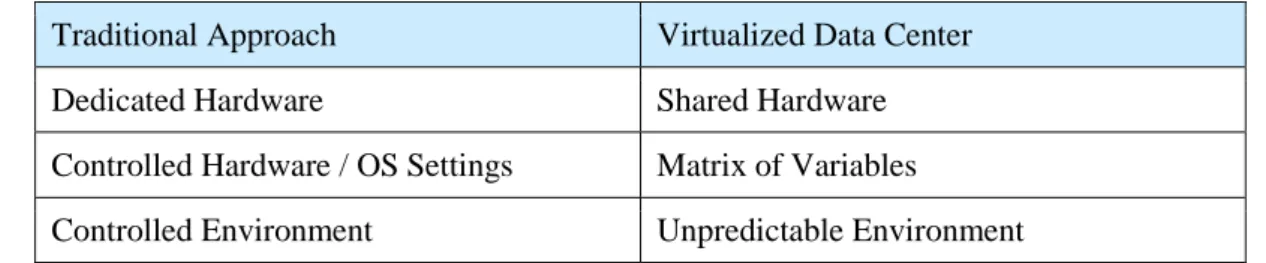
Network Functions Virtualization (NFV) is a trend in today’s telecom business. The following text from a non-proprietary white paper authored by network opera-tors clarifies the motivation for the network virtualization concept:
Network Operators’ networks are populated with a large and increas-ing variety of proprietary hardware appliances. To launch a new net-work service often requires yet another variety and finding the space and power to accommodate these boxes is becoming increasingly dif-ficult; compounded by the increasing costs of energy, capital invest-ment challenges and the rarity of skills necessary to design, integrate and operate increasingly complex hardware-based appliances. More-over, hardware-based appliances rapidly reach end of life, requiring much of the procure- design-integrate-deploy cycle to be repeated with little or no revenue benefit. Worse, hardware lifecycles are be-coming shorter as technology and services innovation accelerates, inhibiting the roll out of new revenue earning network services and constraining innovation in an increasingly network-centric connected world. (ETSI 2014-10-22:3)
This definition illustrates the multiple problems the network operators have today related to hardware-based appliances. These appliances have become increas-ingly difficult; the life span of the appliances has become shorter. All this has led to need for change, and this change is Network Functions Virtualization. The
Network Functions Virtualization aims to address these problems by using stand-ard IT virtualization technology to get different types of network equipment onto industry standard high volume servers, switches and storage. The equipment could then be located in Datacenters, Network Nodes or in the end user premis-es. This method is expected to be applicable to any data plane packet processing and control plane function in fixed and mobile network infrastructures. (ETSI 2014-10-22:3)
On a high-level Network Functions Virtualization can be seen as implementation of network functions as software only entities running over the Network Functions Infrastructure (NFVI). There are three working domains in NFV. They are listed in the table below (Table 8).
Table 8. The working domains in NFV. Data gathered from ETSI 2014-12 a:10. Domain in NFV
1 Virtualized Network Function (VNF), as the SW implementation of a network function, which is capable of running over the NFVI.
2 NFV infrastructure (NFVI), It includes three domains, a hypervisor domain, a compute domain and a network domain, including diversity of physical resources and their virtualization.
3 NFV management and orchestration (NFVO) a) covering the orchestration and lifecycle management of resources, physical and/or software, b) supporting virtu-alization of the infrastructure, and the lifecycle management of VNFs, and c) fo-cusing on all virtualization-specific management tasks that are needed in the NFV framework.
Table 8 above lists the three domains that form the Network Functions Virtualiza-tion framework, which is illustrated in the figure below (Figure 10):
High-level NFV framework. Reprinted from ETSI 2014-12 a:10. Figure 10.
Figure 10 above illustrates the Network Functions Virtualization framework, which enables dynamic construction and management of VNF instances. The frame-work enables also the relationship between VNF’s as for, for example, data, con-trol, management and dependencies. (ETSI 2014-12 a:10)
Benefits of Network Functions Virtualization
Virtualizing Network Functions could potentially offer many benefits including: a) reduced equipment costs which can be achieved through consolidating equip-ment and utilizing the economies of scale; b) reduced power consumption which is also achieved by consolidation and scaling, c) faster Time to Market interval by minimizing the typical network operator cycle of innovation. (ETSI 2014-10-22:3)
Investments into the new functionalities are expected to be much lower for SW-based development than they have used to be for hardware-SW-based functionali-ties. This is because the Network Functions Virtualization should enable network operators to reduce the needs to buy new hardware, and additionally also pro-vide the following additional benefits, listed in the table below (Table 9):
Table 9. Additional benefits when using NFV. Data gathered from ETSI 2014-10-22:3. Benefit
1 Availability of network appliance multi-version allows use of a single platform for different applications. This allows network operators to share resources across services and across different customer bases.
2 Targeted service introduction based on geography or number of customers is pos-sible. It means that the services can be scaled up/down rapidly as required.
3 Enables a wide variety of eco-systems encouraging openness. It opens the virtual appliance markets to new pure software companies, small players and academia. This will encourage bringing new innovative services and new revenue streams quickly at much lower risk.
Table 9 lists the additional benefits that are expected from Network Functions Virtualization. The first listed benefit means multi-vendor environment and many different configurations, the second leads to the scalability requirements, and the last one will bring new vendors, also not traditional telecom vendors, on the ap-plication markets. This may lead new types of situations in operation and mainte-nance later on.
4.2 Network Functions Virtualization Environment
This section discusses the Network Functions Virtualization environment, its fail-ure model, its complexity and testing related aspects.
4.2.1 VNF Failure Models
Presently, there are four failure models that are introduced by moving network functions into a virtualized environment. These four models are dependent of the option selected for the Virtual Network Functions (VNF) deployment. Based on the option selected the impact of failure will vary and the restoration method has to be different. These four different deployment options are presented in the fig-ure below (Figfig-ure 11). (ETSI 2015-01a: 36).