Chapter 7
Microfluidic Combinatorial
Chemistry
7.1
Introduction
Though one can imagine many applications for solvent-resistant microfluidic devices, combinatorial chemistry stands out as particularly suitable due to its need for high integration density as well as chemical inertness. Combinatorial chemistry is a powerful strategy for discovering new chemical substances. It is basically a brute force search strategy in which vast libraries of compounds are randomly or systematically created, then screened for desirable properties. This approach has been used for a wide variety of purposes including the discovery of new drugs, catalysts, and materials. A brief history and introduction to the field is given by DeLue [56].
Depending on the application, the library may consist of molecules (“probes”) tethered to a flat substrate in an array format, molecules in solution in individual wells of microtiter plates, or molecules pooled together (in solution or tethered to beads). High throughput screening is necessary to evaluate large libraries of substances in a reasonable amount of time. Arrays are particularly suitable for performing high-throughput screens due to the ease of deconvolution—that is, once a positive result is detected, the successful molecule can be identified immediately by its position on the array rather than some more elaborate method to determine its identity. In “pool” libraries, deconvolution may be achieved by a tedious omission library approach, or molecules may be tagged during synthesis for instant identification. Arrays are also useful for collecting measurements for all
arrayed substances in parallel under identical experimental conditions. In screens for binding affinity, the level of binding of each probe to a target may be detected by a wide variety of target-labelling schemes such as fluorescence or radioactivity, or other detectable property. Interactions have also been detected by label-free methods such as surface plasmon resonance or atomic force microscopy (AFM). Screens for enzyme activity often involve some detectable transformation of the probes by the analyte, or the localized generation of heat. Numerous ingeneous methods have been reported to screen for other desirable probe properties. Yet, the difficulty in developing screens has hindered the use of combinatorial chemistry in many areas [56].
To investigate some novel approaches for performing combinatorial synthesis and high through-put screening in microfluidic devices, we explored solid-phase synthesis of arrays of biopolymers such as DNA and peptides. DNA arrays have emerged recently for high-throughput analysis of gene expression at the whole-genome level [238] to determine gene function, mechanisms of disease or genetic disorders, and biological response to infection, drugs, or environmental toxins. Gene ex-pression studies are generallytargeted and contain only selected probes of interest, though the use of true combinatorial arrays (containing all possible DNA sequences of a certain length) could in principle provide many benefits (see Chapter 8). Some additional uses of targeted arrays include discovery of splice variants and polymorphisms [199], genotyping [204], discovery and analysis of transcription factors or other DNA-binding proteins [251], and characterization of the methylation state of the genome. Combinatorial arrays have been used for sequencing by hybridization [283], sequence “fingerprinting” [246], and studying the physics and specificity of DNA duplex forma-tion [194, 248], among other applicaforma-tions. Many excellent reviews on DNA array applicaforma-tions have been published [174, 198].
Similarly, peptide arrays have been developed to enable high throughput studies of protein inter-actions. Arrays of whole proteins have also been studied, but short peptides can often capture the full functionality of the whole protein [80, 193], without suffering from problems related to degrada-tion and misfolding. Combinatorial peptide arrays have been used to identify and map the sites of interaction between proteins, most commonly to determine the epitopes of antibodies and to
deter-mine the substrate specificity of enzymes such as kinases. They have also been used in metal-binding assays. Targeted peptide arrays and protein arrays have been used for a huge variety of applications such as: (i) protein expression profiling, (ii) screening for and studying protein-protein, protein-DNA, protein-drug, receptor-ligand, enzyme-substrate, etc. interactions, (iii) identifying posttranslational modifications and splice variants of proteins, (iv) determining the location of protein expression (in-tracellular or secreted), (v) studying mechanisms of diseases and disorders [228], and (vi) identifying secreted biological markers that may be used in diagnostic tests to screen for problems. Protein and peptide arrays have been reviewed extensively [72, 193, 80, 226, 236].
To synthesize arrays of specific compounds or combinatorial sets of compounds, we propose the use of microfluidic devices with dense networks of microvalves to reconfigure flow paths. These devices offer many advantages compared to alternative approaches such as ink-jet printing, robotic deposition, and light-directed synthesis. Microfluidic array synthesis uses conventional (optimized) reagent sets, can operate in a highly parallel fashion, and can potentially achieve very small feature sizes and therefore high densities of surface-bound products.
I begin this chapter with a brief review of the general principles of solid-phase synthesis and the chemistry of DNA and peptide synthesis. Current methods for array synthesis are described next, providing a context in which to argue the principles and advantages of microfluidic array synthesis. The ideas presented here are not specific to DNA and peptide arrays but could be extended to arrays of other biopolymers such as RNA, PNA, oligosaccharides, etc. or arrays of small molecules such as drugs. Subsequently, I report results of experiments applying the microfluidic approach to the in situ synthesis of DNA and peptide arrays. In the final section, I discuss microfluidic device designs for synthesis on trapped solid-support beads rather than on flat surfaces. Bead synthesis can give large quantities of products and can be used in situations where direct synthesis on a flat substrate is not practical.
7.2
Introduction to solid-phase synthesis
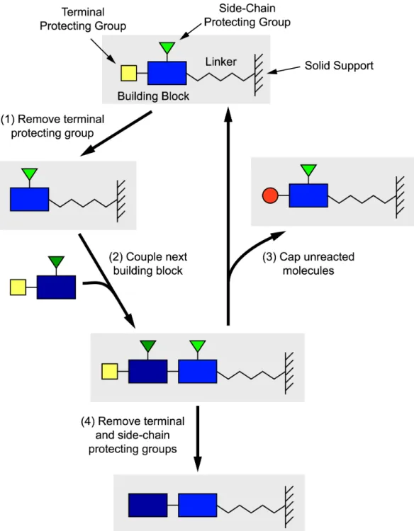
Before describing methods for making combinatorial arrays, it is useful to review the principle of solid-phase synthesis. Synthesis begins at the end of a linker molecule attached to a solid surface. Building blocks are added one at a time to synthesize the desired molecule as depicted in Figure 7.1. The whole set of reactions needed to add a single building block is known as a “cycle”. Solid-phase synthesis is particularly useful for long multi-step syntheses and is an easily automated technique. Because products are covalently tethered to the support, reagents from previous steps can easily be thoroughly washed away before continuing with the next step. However, this also requires that the reactions have nearly quantitative yield as tethered molecules that fail to react cannot be removed. Large excesses of reagents are frequently used to ensure rapid, high-yield reactions. The role of the linker molecule is both to tether the product and to distance the product from the substrate, as reactions (and subsequent assays) are often sterically hindered near surfaces [163, 184, 241, 250, 200]. Biopolymers including DNA (built from nucleotides), RNA, PNA, peptides (built from amino acids), and oligosaccharides are frequently synthesized by this method. Standard libraries of pro-tected building blocks also exist for other classes of molecules. Building blocks need not be linear: they can contain multiple reaction sites to build branched and cyclic molecules.
When synthesizing a single compound, the solid support usually consists of tiny beads of controlled-pore glass (CPG) or swellable polymer resin to enhance the surface area in contact with solution. The beads are trapped in a fritted chamber that allows reagents to be flushed through for each reaction step. Typically the product is cleaved from the substrate during the last step of synthesis. Combinatorial arrays of many tethered compounds, on the other hand, are generated by confining each synthesis reaction to a small region of a planar solid support such as a derivatized glass slide or silicon wafer. This can be achieved by physical masking, which only allows reagents to access the solid support in selected regions, or by another means such as masking the region of light-exposure in a photo-sensitive chemistry step. Many different compounds are synthesized in distinct regions on the same substrate and remain tethered even after the final deprotection.
Figure 7.1: Schematic of solid-phase synthesis. The desired molecules are built up one building block at a time. Each building block contains a terminal protecting group that ensures only a single building block can be attached in a given step. Building blocks also contain side-chain protecting groups that prevent other functional groups in the building block from reacting during synthesis. Synthesis proceeds in a cyclical fashion by the following steps: (1) removing the terminal protecting group; (2) coupling a new building block at the newly opened site; and (3) optionally capping the small percentage of molecules for which coupling was unsuccessful. Capping prevents those molecules from being extended in a later step; otherwise incomplete reactions would lead to “deletion” sequences in addition to truncations (due to capping). Finally, after all building blocks are assembled, all the protecting groups (side chain protecting groups and the terminal protecting group) are removed (step 4). Depending on the application, the product remains affixed to the solid support, or it may be cleaved off.
7.2.1
Cycle efficiency
In any synthesis reaction, a certain fraction of molecules do not react. For solid-phase synthesis, it is common to refer to an overall cycle efficiency, representing the average fraction of desired molecules that react with the new monomer during a complete cycle. When synthesizing polymers (e.g., DNA and peptides), the fraction of desired full-length sequences at the end of nsynthesis cycles is En, whereE is the cycle efficiency.
Imperfect synthesis results in the production of a “distribution” of sequences, including molecules with the desired full-length sequence as well as shorter, truncated molecules whose growth was ter-minated by an earlier capping step. In array applications, where the products remain covalently bound to the substrate, it is impossible to remove the erroneous molecules, and thus it is espe-cially desirable to maximize the cycle efficiency—otherwise, the results of assays can be difficult to interpret.
Failures in the coupling reaction leave deprotected endgroups on molecules, but these can be reacted with a capping agent to immediately terminate the sequence. Typically the capping step is designed to have very high efficiency and can be considered to go to completion. Thus coupling failures lead to truncation errors, in which the erroneous sequences are subsequences of the desired sequence. In DNA hybridization experiments, such sequences can result in a slight loss of specificity: the truncated sequences are able to hybridize to targets that are similar to the desired target, though the binding is weaker due to the shorter sequence length. On the other hand, failures in the
deprotection reaction can lead to “deletion sequences”. When deprotection fails, the molecule will be unable to incorporate the monomer at the subsequent coupling step. Because it looks chemically identical to molecules that were successfully deprotected and coupled (or molecules that were not intended to be deprotected), there is no way it can be identified and terminated. It is likely that the molecule will be successfully deprotected during a later cycle and synthesis will resume. If this occurs, the molecule will contain a “deletion” where incorporation of the monomer failed. In DNA hybridizations, deletion sequences may bind to completely different target molecules, or alter the secondary structure of the probe in the bound or unbound state, leading to fundamental differences
in hybridization kinetics. In addition, the majority of deletion sequences will have length n−1 and will thus be capable of forming relatively stable duplexes with the “wrong” targets, further complicating the interpretation of assay results. Truncated sequences, on the other hand, have little impact because they are much shorter on average and do not exhibit significant binding to targets.
7.2.2
DNA synthesis chemistry
Unlike enzymatic DNA synthesis, which requires a pre-existing template in order to make new DNA, chemical synthesis methods can generate single-stranded DNA from scratch. The most preva-lent chemistry, involving phosphoramidites, has been highly optimized for use in commercial DNA synthesizers over the many decades since its inception in the early 1980s [185]. A history of the development of the chemistry can be found in Reference [109] and details of practice can be found in References [86, 15, 6].
Synthesis of a desired sequence is achieved by coupling protected phosphoramidite nucleosides one at a time to a growing strand. Each nucleoside is added by a four-step room-temperature reaction cycle consisting of deblocking, coupling, capping, and oxidation steps as depicted in Fig-ure 7.2. First, a detritylation reaction is performed to remove the dimethoxytrityl (DMT) group that serves as the terminal protecting group. This is accomplished with trichloroacetic acid (TCA) in dichloromethane (DCM). Next, a new DMT-protected nucleoside phosphoramidite is coupled to the end of the DNA molecule. The nucleoside is dissolved in dry acetonitrile, with tetrazole added to activate the phosphorus linkage, which binds to the active hydroxyl group exposed by the previous detritylation reaction. A capping reaction is performed next with acetic anhydride and N-methylimidazole in tetrahydrofuran (THF) to acetylate any unreacted hydroxyl groups. Finally, the newly formed phosphite linkage is oxidized to a more stable phosphate linkage with a solution of dilute iodine in water, pyridine, and THF. The desired oligonucleotide is built by repeating the cycle to couple the desired nucleosides in sequence. Synthesis proceeds in the 30 →50 direction, though, with modified reagents, the other direction is possible [3]. Several companies distribute pre-mixed reagents for each step of the synthesis cycle. Dry acetonitrile is used as a wash solvent.
Figure 7.2: Chemistry of DNA synthesis. A DNA synthesis cycle begins by removing the dimethy-oxytrityl (DMT) protecting group on the previous nucleoside in the molecule being synthesized, leaving an active hydroxyl (OH) group at the 50 position. A DMT-protected activated phosphoramidite nucleoside is coupled by the phosphorus at its 30 position to this hydroxyl group, extending the chain by one. Syn-thesis thus proceeds in the 30 to 50 direction, with the 30 end tethered to the solid support. The newly formed products are stabilized by oxidizing the phophite linkage to a phosphate linkage, and unreacted molecules are capped by acetylating their hydroxyl groups. For each additional reaction cycle to extend the DNA molecule, the DMT group must first be removed from the previous nucleoside added. (Reproduced from http://www.abrf.org/JBT/2000/September00/sep00bintzler.html. Copyright the Association of Biomolecular Resource Facilities, 2000.)
In standard phosphoramidite chemistry, all steps have extremely high efficiency and are nearly quantitative. The cycle efficiency is limited by the coupling step. With standard nucleotides, cou-pling efficiencies are often 98–99.5%, though with modified bases (including spacers, amine linkers, fluorescent dyes, etc.), efficiencies can be somewhat lower. Note that the coupling reagents (phos-phoramidites and activator) are extremely moisture sensitive so synthesis must use dry reagents and must often be performed in an inert environment to ensure high yields. Coupling efficiency can be monitored by measuring the optical absorbance of the deprotection solution, which contains the cleaved, orange-coloured DMT ion. Some commercial synthesizers are equipped to monitor this in real-time to give an estimate of the efficiency of the previous coupling step.
After synthesis, the cyanoethyl and other side-chain protecting groups must be removed from the synthesized DNA. When synthesizing a single DNA sequence (e.g., in a commercial oligonucleotide synthesizer), this is typically achieved by incubating the solid support material in 30% ammonium hydroxide for 1–2 h at 65oC. The solid support material is supplied with the first nucleotide already attached via a linkage that is cleavable under these same conditions; thus, this reaction simultane-ously deprotects and cleaves the oligonucleotides from the support. To facilitate purification, the final DMT group is sometimes left on the DNA (“DMT-on”).
In the fabrication of DNAarrays, surfaces are frequently derivatized with a linker molecule that provides a terminal hydroxyl group on which synthesis begins. The linker is designed to be stable with respect to the conditions in the final deprotection step so that oligonucleotides remain tethered to the surface. A popular combination is the use of glass substrates derivatized with N-(3-(triethoxysilyl)-propyl)-4-hydroxybutyramide and a final deprotection reaction consisting of immersion in ethylene diamine (EDA) and ethanol (1:1, v/v) for 2 h at room temperature. Note that it is first necessary to remove the final DMT group by a detritylation step at the end of the synthesis (“DMT-off”).
7.2.3
Peptide synthesis chemistry
Solid-phase peptide chemistry predates DNA synthesis chemistry and was introduced by Merrifield in 1963 [192]. A history of the development of the chemistry is provided in [180], and a good summary is provided in [98].
Two types of peptide chemistry are commonly used in current commercial peptide synthesizers: tBoc (t-butyloxycarbonyl) [201] and Fmoc (9-fluorenylmethoxycarbonyl) [209]. These names refer to the terminal (α-amino) protecting group used. The chemistries also differ in their choice of linker, side-chain protecting groups, and conditions for deprotection and cleavage. Fmoc chemistry often has higher yields and purity since the deprotection conditions are milder. In Fmoc chemistry, the Fmoc protecting group is cleaved by a weak base (20% piperidine in dimethylformamide (DMF), v/v), and the amino acid side-chain protecting groups (tButyl) can be removed by a weak acid (trifluoroacetic acid (TFA)) at the end of synthesis. In tBoc chemistry, a weak acid (50% TFA in DCM, v/v) is used for removal of tBoc on every cycle, and the removal of benzyl side-chain protecting groups is performed in a strong acid (hydrofluoric acid (HF)). Fmoc chemistry is often selected to avoid the hazards of working with this acid. The linkers used in commercial peptide synthesizers are designed to be cleaved under the conditions of the final deprotection. In the remainder of this chapter, the use of Fmoc chemistry is assumed.
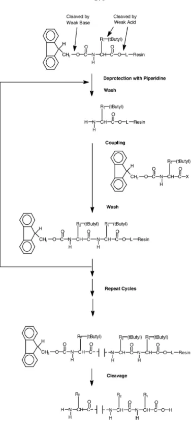
Peptides are synthesized in the C- to N-terminal direction one amino acid at a time as depicted in Figure 7.3. First, the Fmoc protecting group is removed by incubation with piperidine (20% in DMF, v/v) to yield an active amine group at the end of the growing peptide chain. Next, a new Fmoc-protected amino acid is activated and coupled to this amine. Activation is achieved by dissolving the amino acid with 2-(1H-benzotriazol-1-yl)-1,1,3,3-tetramethyluronium hexafluorophos-phate (HBTU), 1-hydroxybenzotriazole (HOBt), and diisopropylethylamine (DIEA) in N-methyl pyrrolidinone (NMP) and DMF to produce an amino acid ester. Typically, the activated ester is reacted in a 4×molar excess. Next, a capping reaction is performed to block any unreacted amine groups. The cycle is repeated to build the desired peptide. After completion, the peptide is thor-oughly washed in dichloromethane and dried. Side-chain protecting groups are then removed by
treatment with 20% TFA in DCM with water as a scavenger. (Depending on amino acid sequence, more concentrated acid such as 95% TFA in water can be used for deprotection and cleavage.) DMF and NMP are used as solvents during reactions and wash steps due to their ability to solvate peptides.
In commercial synthesizers, the linker is designed to be cleaved during the final deprotection step. However, to build a tethered peptide array, it is necessary to use a non-cleavable linker. Several possibilities exist: one can treat glass slides with aminopropyltriethoxy silane, or one can purchase commcercial aminated slides such as ArrayIt SuperAmine substrates (TeleChem International) and Xenoslide A substrates (Xenopore Corp.).
It should be noted that the synthesis conditions are much more forgiving when compared with DNA synthesis. In fact, reactions can be carried out at room temperature in air with no special conditions such as a dry atmosphere [79, 81]. However, one drawback is that the efficiency of the coupling and deblocking steps can depend tremendously on the amino acid sequence synthesized up to that point. (In constrast, the efficiency of DNA synthesis is relatively constant and independent of sequence.) The variation in efficiency is due to the secondary structure of certain peptide sequences that can “bury” the N-terminus, hindering the access of reagents. In a synthesized peptidearray, such variations can lead to different peptide densities and purities in each array location. For this reason, to obtain high purity peptides, testing of completeness should be performed during each reaction cycle. Numerous test methods are reviewed by Sabatinoet al.[235].
A ninhydrin test can be performed during manual synthesis to determine whether the coupling step has gone to completion. A small amount of solid support resin is removed from the support column and mixed with the 2–3 drops each of the following three solutions: ninhydrin (0.5 g) in ethanol (10 mL), phenol (80 g) in ethanol (20 mL), and aqueous 0.001 M KCN (0.4 mL) in pyridine (20 mL). After mixing, the solution is heated to 110oC for 5 min. If the solution turns blue, this signifies the presence of amine groups and thus an incomplete coupling reaction. The coupling step can be repeated immediately if necessary. Measurements of the optical absorbance at 570 nm can quantitate the degree of completeness. Note that the ninhydrin test can also be used after the
Figure 7.3: Fmoc peptide synthesis chemistry. In each synthesis cycle, the terminal Fmoc protecting group is removed from the growing peptide chain by piperidine, and an Fmoc-protected, activated amino acid is then coupled to the newly exposed amine. This cycle is repeated to build the desired peptide. Synthesis proceeds from the C-terminus to the N-terminus, with the C-terminus tethered to the solid support. Once the peptide is completed, the tButyl side chain protecting groups are removed and the peptide may be cleaved from the support. Note that “L” refers to the linker by which the peptide is attached to the solid support resin. (Reproduced from [7]. Copyright Applied Biosystems, 2004.)
deprotection step to verify completion of Fmoc removal. For synthesis on a substrate, the ninhydrin test is not a practical method for obtaining reaction feedback because amine groups are destroyed in the test and are thus not available for re-coupling should incomplete coupling be indicated. In the technique known as SPOT synthesis, real-time monitoring of coupling is performed with bromophenol blue [79]. The indicator can be added with the coupling reagents and as the reaction proceeds to completion, the colour changes from blue to yellow. Alternatively, the test can also be performed at the end of the coupling step and coupling repeated if the test fails. This is a non-destructive test and can thus be incorporated into anin situ array synthesis.
In the deprotection step, Fmoc is removed by reacting two equivalents of piperidine. One equiva-lent acts as a general base to remove the base-labile Fmoc group from the N-terminus of the peptide, while the second covalently binds to the Fmoc group and forms a fulvene-piperidine adduct. The concentration of this adduct can be measured by its optical absorbance,A301, at 301 nm. In a typical test, the absorbance is compared to a blank (consisting of the same solutions but without the Fmoc) and the amount of Fmoc is determined by an empirical formula. Commercial peptide synthesizers monitor the release of the Fmoc group during the deblocking step in real time. The removal of Fmoc by piperidine generates a conductive carbamate salt that can be detected by a conductivity measurement. Generally, the amount of Fmoc released is measured in several successive treatments with the deprotection agent. Only when the difference between successive measurements is below some threshold is the deprotection step complete. Often the difficulty of deprotection is related to the difficulty of coupling the next amino acid, so commercial synthesizers increase the coupling times accordingly.
7.3
Synthesizing DNA and peptide arrays
Arrays are convenient and powerful tools for many types of high throughput measurements. Perform-ing parallel measurements on a sPerform-ingle substrate reduces costs, increases convenience, and ensures identical experimental conditions among all measurements. High density arrays may also permit multiple replicates of each measurement in order to further increase data quality [136]. Currently,
most DNA and peptide arrays are “targeted”, containing molecule sequences carefully selected to probe the particular biology being studied. Because such arrays require prior knowledge of what to look for, they can serve only as a platform for hypothesis-driven research [193]. Combinatorial DNA and peptide arrays, on the other hand, containall possible sequences of a certain length. Since no sequences are omitted, even completely unexpected interactions can be detected, potentially leading to novel discoveries [193] that would not have been made had sequences been hand-selected. The inclusion of all possible sequences has additional advantages, even in hypothesis-driven experiments. For example, once an experiment has been performed, it need not be repeated when new genes are discovered or when gene sequences are updated; instead, the existing data can simply be reanalyzed. Another possibility is that combinatorial arrays could form the basis of a standardized array design that can be used in any type of experiment with any organism—only the computer analysis would differ for each case. In Chapter 8, we argue that even experiments with the complexity of gene expression analysis can be performed with universal DNAn-mer arrays.
In a combinatorial array, the number of different probe sequences, (mn), increases exponentially with the sequence length,n, where m is the number of monomers. (m = 4 for DNA and m= 20 for peptides, assuming only natural building blocks.) Current technologies are capable of printing arrays with sizes up to roughly a million spots, sufficient for a combinatorial 10-mer DNA array or 5-mer peptide array. While these sizes are useful for several applications, other areas will require significantly longer sequences. For example, we argue in Chapter 8 that universal gene expression analysis will require DNA arrays with at least all possible 13-mers. Due to the extremely large number of different probes, combinatorial arrays must be fabricated byin situ (in-place) synthesis. Methods such as robotic or ink-jet deposition ofpre-synthesized DNA strands are not practical due to the enormous costs associated with synthesizing, storing, and handling all the individual probes. These problems would undoubtedly be exacerbated as array sizes increase further.
In the remainder of this section, I briefly review several large-scale in situ array synthesis tech-nologies that have emerged during the past decade and discuss their merits and drawbacks in terms of minimum feature size, chemistry efficiency, and whether the method is serial or parallel in
na-ture. We have developed a new microfluidic synthesis technology, described in the next section, that strives to address important shortcomings of the other methods.
7.3.1
Array replication
Before delving into technologies for arrayfabrication, it should be noted that several methods have been reported for arrayreplication. Such methods provide a means to economically produce many copies from a single “master” array. The time and cost associated with fabrication of the original master array thus become less important than other factors such as fabrication density and quality. Replication occurs in parallel and is independent of the number of spots on the master.
Kumar et al. [155] report a method for replicating DNA arrays based on strand transfer. A “master chip” containing DNA attached by disulfide bonds is brought into contact with a “print chip” containing an acrylamide layer. When heated, some molecules are transferred from the master chip to the print chip; the copying process takes less than 1 min. Presumably libraries of other types of molecules could be replicated in a similar fashion. Note that the copies are not identical to the master—the density of molecules at each array site is lower. Since the master chip is depleted each time, the number of copies is limited.
The “nanostamping” technique reported by Yu et al.[303] could be used, in principle, to make unlimited copies of a single-stranded master array with identical molecular density. First, a set of oligonucleotides is hybridized to the master. Each oligo is linked to a functional group that forms a bond with the target substrate when it is brought into contact. Heating then denatures the DNA duplexes, leaving the original pattern on the master array and the copied (hybridized) pattern on the target substrate. Note that this method does not require any special attachment of oligos to the master array. In fact, the copies can easily be used as masters, permitting an exponentially increasing rate of array production.1 Because the master array will selectively pull down the complementary strands to the proper parts of the array during hybridization, all of the oligos can be pooled together, greatly simplifying their storage and handling. In fact, it is even conceivable that the oligo mixture
1Of course, it is important to account for the fact that the copy contains sequencescomplementaryto the originals.
However, for a combinatorial array of all possible sequences, both the original and complementary arrays contain identical sets of compounds.
be generated by a simple pooled synthesis approach such as mix and split. (Any unneeded sequences are simply ignored.) This method seems quite practical for mass production, though it is not clear whether copies of copies would exhibit reductions in resolution or reductions in sequence purity and density (due to imperfect hybridization).
Mitra and Church [196] report a method for amplifying deposited DNA by performing PCR within a polyacrylamide film on the surface of a glass microscope slide. Products remain localized near the original spots. If the primers contain appropriate functional groups, the product molecules can bond to a target substrate brought into contact with the original array. Like the previous method, potentially unlimited numbers of copies can be made from a single master.
7.3.2
Array fabrication by deposition
In robotic deposition, a “pen” (or “pin”) is dipped into a solution containing DNA or peptide molecules of a particular sequence and then briefly brought into contact with a substrate, leaving a small droplet of the solution behind. As the droplet dries, the molecules become immobilized on the substrate surface. Often, the pens contain special reservoirs such that the initial loading phase stores enough solution to print a spot on each of hundreds of substrates in succession. Robotic spotting machines are sold commercially or can be built relatively easily from parts [60]. As discussed above, it is not economical to individually synthesize each sequence in an oligonucleotide array, therefore deposition methods are typically reserved for printing isolated biological materials such as long cDNA strands or proteins.
The size of the printed droplet is determined by surface tension and the shape of the printing tip. With commercial tips, spot sizes are typically 100 µm or greater, though 50–75 µm spots are possible according to specifications from several manufacturers (Majer Precision MicroQuill pins [215], and ArrayIt 946 [121] and ArrayIt Stealth [122] pins). Pens are most frequently fabricated from stainless steel or titanium, though ceramic tips have been reported to be more durable and capable of printing smaller features [92]. Typically, they are cylindrical with a slot and reservoir cut into the pointed tip. In our lab, Matthew Reese microfabricated trench-shaped stainless steel pens
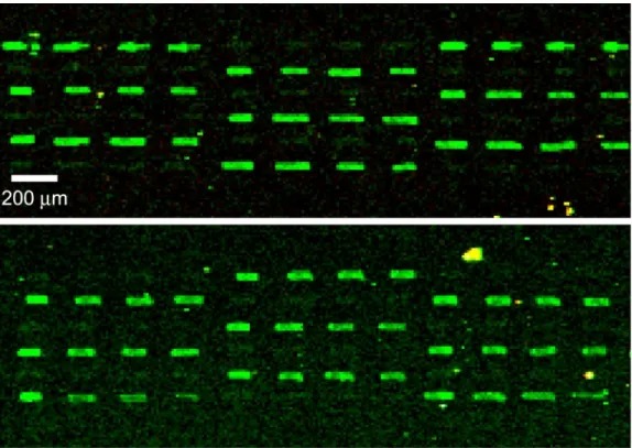
by etching stainless 12.7µm thick steel foil from both surfaces (see Figure 7.4). At the tip, the pens were approximately 100 µm wide by 13µm thick, containing a trench about 30µm wide by 7 µm deep. We demonstrated printing of spots as small as 20×40 µm (corresponding to densities up to 25000 spots/cm2) with dye [225, 276]. Furthermore, we demonstrated printing of two different DNA 10-mers in an alternating array pattern and showed that complementary oligos exhibited the correct specificity when hybridized to these arrays (Figure 7.5).
Figure 7.4: Microfabricated stainless steel trench pens. (a) Comparison of commercial slot pen (left) machined by conventional methods with our microfabricated trench pen (right). The tip sizes are similar; however, the trench pens are capable of smaller spot sizes. This is presumably due in part to the printing method, in which the flexible trench pens are tapped on the surface at an angle. We observed the spot size to be comparable to the trench size (30µm wide by 7µm deep), rather than the total tip surface area as is observed in conventional pens that are tapped on the surface in a perpendicular direction. The trench pen is shown in side view (top right) and overhead view (bottom right). (b) A collection of microfabricated stainless steel pens. The various pen designs incorporate features such as reservoirs, support struts, and trenches with different aspect ratios. The ability to fabricate pens using photolithography rather than conventional machining gives considerable design flexibility. Although our lithographic process at the time was limited to a lateral resolution of about 30µm, one could scale down the design to produce smaller pens and spot sizes. (Adapted from [225] with permission. Copyright Cold Spring Harbor Laboratory Press, 2003.)
Dip-pen nanolithography is a related technique that uses an atomic force microscope (AFM) tip to write thin lines or spots onto a surface. Liquid is transferred from the tip to the surface when brought into contact. Patterns produced by this method have extremely small features. Demers
et al.[58] report the spotting of DNA onto gold and silicon dioxide surfaces at spot sizes down to about 50 nm. 130 nm protein spots have been demonstrated by Limet al.[168], and lines of biotin 75 nm in width were reported by Junget al. [139]. Due to the slow printing speed (up to several
Figure 7.5: Hybridization to an array printed by stainless steel trench pens. Two 10-mer probe sequences were spotted onto a glass substrate with our microfabricated trench pen in an alternating fashion. (Top) Complement 1 hybridizes selectively to probe 10mer-1 and does not hybridize to probe 10mer-2 as shown in this fluorescence image. (Bottom) After boiling and washing to remove the hybridized target, the array was re-hybridized with Complement 2, which similarly shows specificity in its binding only to probe 10mer-2. Note that two successive hybridizations were necessary because both targets were labelled with the same dye—Cy3. The hybridization protocol is described in Section 7.5. (Adapted from [225] with permission. Copyright Cold Spring Harbor Laboratory Press, 2003.)
seconds for a small feature), it is not likely that large ordered arrays could practically be fabricated by dip-pen nanolithography unless large tip arrays were available. Surfactants have been reported to improve wetting properties and to improve the reliability and speed of printing. Their use may even extend the range of “inks” that can be printed [139].
Additional techniques have been used for depositing pre-existing DNA and peptides into array patterns. For example, bubble jet technology was used to print arrays of oligos [204, 99]. The authors optimized the printing solvent and demonstrated that printing does not result in DNA damage, even for sequences up to 300 bp in length. Spot sizes on the order of 75µm were demonstrated.
Feng and Nerenberg [76] have developed a microelectronic deposition strategy in which the substrate is patterned with electrodes to which different voltages can be applied. When an electrode is positively charged, it attracts (negatively charged) DNA. With appropriate functional groups, the DNA can attach covalently to the electrode. In this manner, DNA in solution can be selectively pulled down to desired array locations. This method is not suitable for large arrays, however, because solutions containing each desired probe sequence must be applied to the chip insequence. An advantage of the electrodes is that different voltages can be applied to each point during assays such as hybridization to locally control the stringency and provide optimal specificity at each site. This is important in applications where small differences in binding must be distinguished, such as SNP (single nucleotide polymorphism) and STR (short tandem repeat) analysis. Hybridization is also very rapid using these electrodes, occurring in just seconds. Livacheet al.[172] report a similar method in which electrodes on a chip determine the location of electropolymerization of polypyrrole mixed with oligonucleotides or peptides grafted to pyrrole groups.
As discussed earlier, deposition methods all suffer from the drawback that sequences must be indi-vidually synthesized or isolated, stored, and manipulated. For very large arrays, this is prohibitively expensive, and methods must be based on in situ synthesis instead. Furthermore, molecules are printedserially so these methods are not scalable to very large collections of compounds. In addi-tion, deposition arrays often require longer fabrication times than synthesis techniques—the need to load the print-head with each probe solution adds a considerable amount of time to the print run.
The loading time can be amortized over many arrays, however, by printing spots on several arrays after each load. Stimpsonet al.[253] report an additional interesting amortization strategy in which
lines of oligonucleotides were printed on a membrane by thermal ink-jet printing. The membrane was subsequently rolled up (will lines parallel to the roll axis) and sliced into a large number of disk-shaped arrays. Deposition methods have the additional drawback that an immobilization strategy is needed. Tagging biological materials such as RNA, DNA, or proteins with functional groups to promote tethering at specific sites can be tricky. On the other hand, in situ synthesis naturally incorporates a single well-controlled point of attachment.
One significant advantage of deposition techniques such as dip-pen nanolithography is the ex-tremely high density that is theoretically possible. Another advantage is that higher sequence purity is possible. Inin situ synthesis, all molecules—including those with truncation or deletion errors— are covalently linked to the substrate and cannot be removed. When molecules are pre-synthesized, they can be purified prior to spotting. One clever technique is to incorporate a covalent attachment group as the last oligonucleotide synthesis step. Molecules that did not reach full length lack this group and are washed away rather than being immobilized when spotted on a substrate.
7.3.3
Ink-jet and robotic synthesis of arrays
Ink-jet and roboticsynthesisare very similar to the deposition methods discussed previously, except that synthesis reagents—rather than pre-synthesized molecules—are deposited. Arbitrary patterns of probes can be fabricated by selecting the series of reagents delivered to each array location.
Hugheset al.[113] used ink-jet printing to deposit reagents for the synthesis of arrays of oligonu-cleotides as long as 60-mers with a stepwise yield of 94–98%. Arrays as large as 25000 spots on a 25×75 mm glass slide were demonstrated. Printing must be performed under a dry inert at-mostphere. Butler et al. [31] report an improved technique wherein arrays are synthesized on a substrate patterned with regions of differing surface tension. Synthesis occurs within the boundaries of circular features treated with an amino-terminated organosilane (3-aminopropyltriethoxysilane). These features are surrounded by a perfluorosilanated surface. The difference in surface tension
confines reagents to highly localized areas—in principle much smaller than the normal size of an ink-jet droplet. A mixed solvent system (10% acetonitrile, 90% adiponitrile) limits evaporation dur-ing reagent delivery and durdur-ing coupldur-ing reactions, resultdur-ing in coupldur-ing efficiencies of 97–99%. A detailed design for building an inkjet synthesizer was published by Laustedet al. [158]. In ink-jet synthesis, only the phosphoramidites need be deposited by ink-jet printing—the remainder of the reactions in each synthesis cycle can be done in bulk on the whole slide. These methods are both examples of confining thecoupling reagents to determine the synthesis location.
Synthesis of peptide arrays by the SPOT technique involves manual or automated pipetting of spots of reagents and Fmoc-protected amino acid monomers on a support surface such as a cellulose membrane [79]. Generally, the coupling reaction is performed by spotting, and additional synthesis reactions are performed by washing the whole membrane in a reagent bath. Spot size is determined by the droplet volume and properties of the membrane, with densities of hundreds of sequences per cm2 possible. A unique feature of SPOT synthesis is that evaporation in the “open reactor” format leads to a maintenance of high reagent concentrations, improving yields [81]. Unlike for DNA synthesis, a dry inert gas environment is not required.
In addition to methods for creating arrays on flat substrates, automated methods have also been reported for synthesizing compounds in microtiter plates. Chenget al. [39] demonstrated the synthesis of DNA in four 384-well plates (for a total of 1536 reaction sites) via a robotic pipetting system. Stepwise yields of up to 99.3% were observed. Each well contains a small amount of solid-support resin that is trapped by a frit. A vacuum system draws reagents out of the bottom of wells through the frits after each reaction step. While not suitable for producing particularly large sets of compounds, this method provides a means to reduce the cost of DNA synthesis when the quantities of product required are significantly smaller than the 40 nmol lower limit of commercial synthesizers. The products could be used individually or assays could be performed directly in the microtiter plates.
Ink-jet and robotic synthesis solve many of the shortcomings of deposition methods, but they are still serial techniques, and synthesis of extremely large arrays would be prohibitively time-consuming.
7.3.4
Light-directed synthesis
In light-directed synthesis, the synthesis chemistry is sensitive to light during a particular step (usually deprotection), allowing photolithographic methods to be used for patterning regions of the surface in which synthesis occurs. The use of photolithographic techniques has the potential to reduce spot sizes by an order of magnitude or more compared with ink-jet printing and spotting methods. Light-directed chemistries for both DNA and peptide synthesis have been reported. Typically the substrate is mounted in a flow cell connected to conventional DNA or peptide synthesizer and is exposed to a pattern of light during the deprotection step in each synthesis cycle. Deprotection occurs only in the illuminated areas. When coupling reagents are flooded across the substrate, coupling will only occur in these deprotected regions. Light-directed methods offer a high degree of parallelism, because all molecules requiring the same monomer at a particular position in their sequence can be processed simultaneously. The selection of photomask pattern and monomer in each synthesis cycle determines the compounds that are generated on the array.
Fodor et al. [78] modified standard peptide synthesis chemistry to incorporate the photolabile blocking group nitroveratryloxycarbonyl (NVOC) instead of the standard blocking group. Peptide arrays with spot sizes of 50 µm were demonstrated with cycle efficiencies of 85–95%. Arrays with features as small as 18 µm have been reported in the literature [169]; however, the technology is thought to be capable of printing arrays with 10 µm features, corresponding to a density of 106 probes/cm2 [11]. Illumination through a chrome photomask deblocks only selected areas of the substrate. Up to 20nphotomasks are needed to synthesize an array ofn-mers—one mask for each of the 20 natural amino acids in each position of the sequence. The synthesis of oligonucleotides using NVOC protecting groups was also reported. Pease et al. [207] later extended this oligonucleotide work and reported the synthesis of a 256-octanucleotide DNA array via standard phosphoramidite chemistry modified with the photolabile (alpha-methyl-2-nitropiperonyl)oxycarbonyl (MeNPOC) protecting group. Synthesis cycle efficiencies were reported to be 95–100% in one assay and 85– 98% in another. A more systematic study of deprotection efficiency by McGallet al.[189] suggests efficiencies are in the range 92–94%.
With photolabile protecting groups such as NVOC and MeNPOC, the relatively low efficiency of the photodeprotection step dominates the cycle efficiency. Thus, array positions typically contain a much smaller fraction of full-length sequences compared with arrays synthesized by conventional phosphoramidite chemistry. For example, the fraction of full-length 25-mers is only 21% assuming 94% efficiency, while it is 88% assuming 99.5% efficiency. This limits the maximum sequence length that can be produced and also complicates the interpretation of hybridization results since the incomplete sequences cannot be removed from the array. Lower efficiencies have been reported to increase hybridization efficiency due to reduced molecular crowding [11], but it is preferable to achieve this by controlling the density of functional groups on the derivatized surface.
The relatively low efficiency of photodeprotection introduces another problem—the presence of deletion sequences—that further complicates the analysis of array assays. Affymetrix, a commercial manufacturer of DNA arrays fabricated using photodeprotection, typically incorporates several dif-ferent dedicated sequences to detecteach desired gene target. Proprietary calibrations and analyses are used to determine the concentration of the target molecule in the sample based on the combi-nation of hybridization measurements. A better understanding and quantization of the synthesis errors may also help to interpret assays. For example, a method to monitor the quality of synthesis in real-time has been reported, in which cleavable fluorescent amidites are coupled in a final step, then measured and removed [17]. Garland and Serafinowski [90] studied the effects of stray light on synthesis quality, an effect that can lead to additional “contaminants” such as extra-long sequences due to unintended deprotection.
To increase the flexibility of array production by eliminating the up-front cost of chrome pho-tomask fabrication for each new design, programmable digital micromirror arrays have been used to provide the illumination pattern during the deprotection step [243, 23, 14]. This is particularly useful in peptide chemistry, in which there are many monomers, each requiring a different illumi-nation pattern for each cycle of synthesis. A micromirror array contains tiny mirrors that can be individually rotated to one of two positions: in one position, light is deflected away from the syn-thesis substrate; in the other, light is directed towards it. Micromirror fabrication is described in
Reference [161]. Spot sizes as small as 14 µm separated by a 3µm gap and array sizes as large as 200000 features have been demonstrated [203, 36]. Oligonucleotide arrays created with this technol-ogy were successfully used in gene expression studies (validated by quantitative PCR) and in tiling arrays to find optimal probes for a target gene. The chemistry involved the photolabile blocking group 2-nitrophenyl propoxycarbonyl (NPPOC) that exhibits average stepwise yields from 96–99%, depending on the nucleoside. Beier and Hoheisel [17] report the efficiency of the previously used protecting group MeNPOC to be only 88% that of NPPOC under optimized conditions for each blocking group.
Shin et al. [242] optimized the surface derivatization and linker chemistry for peptide arrays produced using micromirror arrays and NVOC chemistry. Glass treatment with 3-glycidoxypropyl-trimethoxysilane, chitosan, and either the spacers N-NVOC-6-aminocaproic acid or N-NVOC-O,O0 -bis-(2-aminopropyl)polypropylene glycol 500-succinic acid resulted in the best signal-to-noise ratio in binding assays and did not require a BSA passivation treatment.
Another variant of light-directed DNA and peptide synthesis chemistry involves the use of a pho-togenerated acid (PGA) during deprotection. This allows standard, highly efficient, acid-cleavable protecting group chemistry to be used (e.g., DMT for DNA and tBoc for peptides). Baroneet al.[11] report a method wherein the acid is generated by a photosensitive polymer film deposited over the array prior to each exposure step. Stepwise synthesis yields up to 98% were observed, and further-more, the speed of deprotection was improved by an order of magnitude. A similar method (though not using PGA) is the use of a standard photoresist film covering the oligonucleotides or peptides. The photoresist is patterned by conventional photolithographic methods, leaving parts of the surface exposed. These open areas can then be treated with an acid for conventional deprotection whereas the covered areas remain protected. Feature sizes down to 10×10µm have been reported with this method [283]. One disadvantage of these methods is that the conditions for removing the overlayer may be harsh and lead to contamination [57].
Gaoet al.[87] report the use of solution photogenerated acids for standard DMT deprotection of DNA oligonucleotides in a light-directed fashion. A photosensitive compound is added during
the deprotection step that generates an acid in solution when illuminated. Average yields greater than 98% were observed—a significant improvement over direct photocleaving of NVOC, MeNPOC, and NPPOC. The use of a solution acid generator is more convenient than applying and removing a polymer layer in each step. Photoacid generators have also been used in light-directed peptide synthesis based on conventional tBoc chemistry [208, 88]. Acid diffusion between reaction sites must be prevented by a physical barrier such as a hydrophobic film that confines reactions to discrete droplets on the surface. Otherwise, acid can diffuse hundreds of microns during the deprotection time (minutes) preventing the fabrication of high density arrays. Gaoet al.[88] report the use of a substrate containing microchannels to be an effective means to isolate reaction regions. One could also imagine adding other compounds to the deprotection cocktail, such as quenchers, which are used in photoresists and 2-photon stereolithography resins to maintain high contrast. An epitope binding assay was performed with PGA-deprotected peptide chips, as was a metal binding assay [88]. Preliminary results for photo-generatedbase deprotection of Fmoc were also reported.
Aside from higher cycle efficiencies, the use of a photoacid generator offers many other advantages. Since light-sensitivity is relegated to the photoacid generator, standard off-the-shelf chemicals can be used in all aspects of the synthesis. Light-directed synthesis can thus easily be extended to the synthesis of other biomolecules, for which monomers are not available with photolabile protecting groups. In addition, the inclusion of non-standard nucleotides or amino acids is simpler as it is not necessary to first devise a method to attach a photolabile protecting group. Furthermore, different photogenerated species (e.g., acids and bases) could be used at different stages of synthesis to incorporate a wider variety of monomer combinations. To achieve the same flexibility with photolabile protecting groups would require groups sensitive to different illumination wavelengths, for example. Finally, the non-linear response of photogenerated reagents gives sharper contrast (i.e., sharper array spot boundaries) than the linear response of direct photolabile-protecting-group removal [88].
The array densities that can be achieved with light-directed synthesis methods are limited by many factors: the resolution of the photomask or micromirror array, the diffraction limit of the light,
and the diffusion of photogenerated acids, if used. Feature sizes as small as 10µm have been reported using photomasks [283], while feature sizes in arrays fabricated with digital micromirror arrays have reached 14 µm [203]. Physical masking techniques (e.g., using microchannels) may enable smaller feature sizes.
As with ink-jet and other spotting methods, reaction sites are fully addressable in light-directed synthesis. Thus it is possible to generate arbitrary arrays of sequences. Of course, combinatorial arrays are also possible [78].
7.4
Microfluidic combinatorial synthesis
To address many of the issues raised in the previous sections, we developed a novel method to synthesize combinatorial arrays within microfluidic devices. The principles of operation, design details, and relationship to other work in the field are described here.
7.4.1
Principle of operation
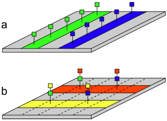
Southern et al. [248] reported an elegant method for in situ synthesis of combinatorial sets of oligonucleotides. The procedure for making arrays is depicted schematically in Figure 7.6. The authors used a physical masking procedure to confine coupling reactions to parallel stripes along a flat derivatized solid support, with different nucleotides flowed in different stripes. In one “step” of the synthesis, stripes are oriented in one direction; in the next, they are oriented in the perpendicular direction. Compounds are built up at the points where stripes intersect. The set of sequences that are synthesized on the array is determined by the number of steps and by selection of which nucleotides flow in each stripe during each step. For example, an array of all possible 6-mers can be synthesized in 6 steps according to the scheme in Figure 7.7. Southernet al.synthesized an array of all possible octapurine DNA sequences (i.e., all possible DNA 8-mers composed of adenine (A) and guanine (G)) in eight synthesis steps [248]. Other combinatorial sets are possible: for example, reducing the size of the monomer set in certain synthesis steps to one (so all stripes carry the same nucleotide) generates
arrays where all oligonucleotides are identical at certain positions (e.g., fixed flanking sequences around a variable sequence).
Figure 7.6: Principle of in situ solid-phase synthesis by surface striping. Using microchannels or other means, one can confine reagents to flow in a thin stripe along the substrate surface. By flowing the appropriate reagents to perform coupling of a monomer (e.g., nucleotide, amino acid, etc.), one obtains a stripe along the substrate where that monomer has been coupled to the surface. In (a), two stripes are created: green 1-mers and blue 1-mers. If one now rotates the apparatus so that fluids flow along the surface in the perpendicular direction, one obtains new stripes of monomers. Where the new stripes cross old ones, the second monomer is added to the first, thus generating a 2-mer at the stripe intersections. In (b), two new stripes (red and yellow) are generated. At the intersections are green-yellow, blue-yellow, green-red, and blue-red 2-mers. In the third step, the orientation and stripe positions match those of the first step. As this process is continued, the desired products continue to be built up at the intersections. Aftern steps, one obtainsn-mers. Molecules along other parts of the stripes (i.e., not at intersections) will consist ofn/2-mers, but can be shortened to 1-mers if appropriate capping reactions are performed early in the synthesis.
It should be noted that a similar scheme of row and column patterning for synthesis of com-binatorial arrays was reported by Peaseet al.[207] in conjunction withlight-directed synthesis. A 256-octanucleotide matrix was synthesized and a labelled oligo selectively hybridized to the correct spot. Patterning was achieved by light masking rather than physical confinement of reagent flow.
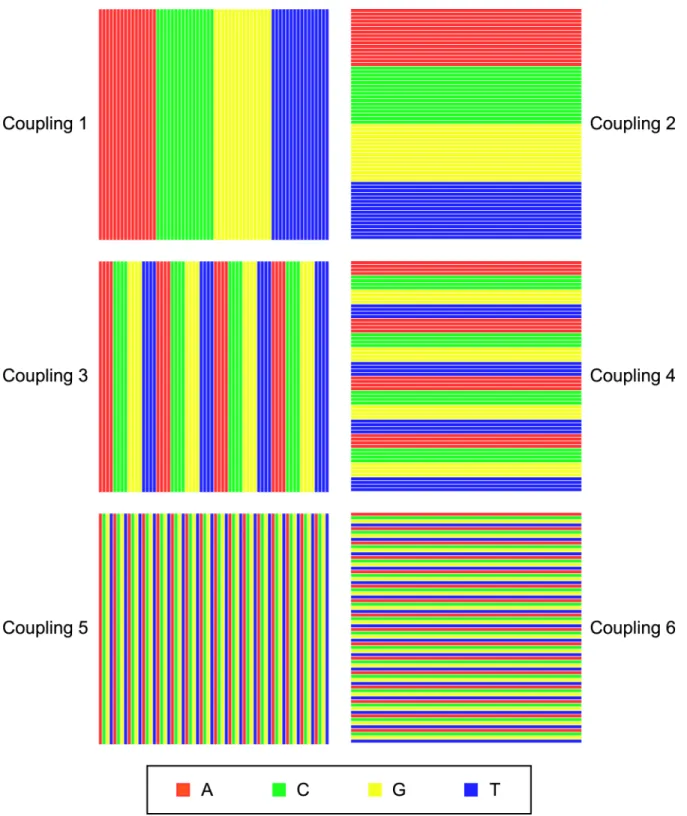
Figure 7.7: Pattern of nucleotide coupling steps to build all DNA 6-mers in 6 steps. There are 4 “monomers” from which DNA is synthesized: A, C, G, and T. To make all possible 6-mers by the stripe synthesis method, one requires an array with 46 = 4096 spots, or 64 rows by 64 columns. In the first coupling step, 16 adjacent stripes are patterned with A, 16 with C, 16 with G, and 16 with T. In the second coupling step, the flow orientation is rotated 90o, and the same set of monomers is flowed. For the third step, each of the four inital groups of 16 channels having the same monomer is subdivided into 4 groups of 4 channels as shown. The fourth step is identical except rotated by 90o. The fifth step further subdivides each of the previous groups of 4 channels into four individual channels, and the sixth is simply a rotated version of the same flow pattern. After all 6-steps, one obtains all possible DNA 6-mers.
7.4.2
Microfluidic architecture
Southernet al.used a macroscopic masking scheme to confine reagent flow to stripes [251]. Lines of silicone rubber or polyethylene tubing were glued to one glass plate which could be clamped to the substrate to confine flow to the spaces between adjacent lines of tubing. After each coupling step, the masking apparatus was removed from the substrate, rotated 90o, realigned, and reattached to the substrate.2
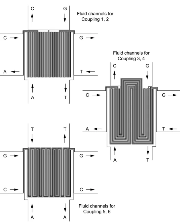
Masking could just as easily be achieved by reversibly sealing a microfluidic device containing parallel channels to the substrate. The use of micron-scale channels reduces the spot size (size of stripe intersections) and permits a larger number of compounds to be synthesized in a given area. With the demonstration of nanoscale (100 nm) channels [50], the possibility exists for array densities far greater than those achieved by ink-jet or light-directed synthesis methods. In the simplest case, one could use a 1-layer microfluidic device containing a series of parallel fluid channels, each with dedicated input and ouput ports. However, for large array sizes, the microfluidic device would need an impractically large number of connections. Furthermore, these connections would need to be reconfigured for each step of the synthesis to deliver a different configuration of nucleotides to the various channels. Instead, one can have simply a dedicated pair of connections (input and output) for each of the four nucleotides, with the fluidic network taking care of routing the inputs to the proper subset of channels. Reconfiguration of which nucleotides are assigned to each channel can be achieved simply by using a different device design for each step of the synthesis. For example, I designed the set of three 1-layer microfluidic devices shown in Figure 7.8 to synthesize all possible 6-mers (Figure 7.7). Each device is used for two synthesis steps (once in each orientation) for a total of 6 steps. While probably not a useful array size for a DNA array, this 6-mer array synthesizer design serves as a non-trivial demonstration that issues such as the number of off-chip connections can be addressed in a scalable way.
2It should be noted that Southern et al.reported an additional interesting scheme using circular or
diamond-shaped flow cells to synthesize “scanning arrays” or “tiling arrays” consisting of all possible subsequences of a desired sequence [249, 247]. Each nucleotide of the sequence is coupled in turn in the flow cell, each time displacing the flow cell by a small amount in one direction such that its new position overlaps the old one. The choice of the amount of overlap determines the maximum size of n-mers produced.
Figure 7.8: Scheme for synthesizing all DNA 6-mers with passive microfluidic devices. Essentially the passive device consists of 64 parallel channels. To reduce the number of chip inlets, these channels are tied together such that all channels carrying nucleotide A are joined to a single inlet, etc. Channels are tied together in series (via a serpentine pattern) rather than parallel to ensure that the fluid passes through all the desired channels. A parallel design would allow much faster operation as all relevant stripes could be filled simultaneously. Because there are three different flow patterns (each used in two perpendicular orientations for a total of six, see Figure 7.7), three separate microfluidic devices were designed. One is used during steps 1 and 2 (with removal, rotation, realignment, and reattachment between these steps), one during steps 3 and 4, and the last during steps 5 and 6. In general, n/2 different devices are needed to synthesize an array of all possiblen-mers. In each of the three channel patterns, the input pins are labelled with the nucleotide they carry. Note that, in practice, each device contained alignment marks to be aligned with matching marks etched or patterned onto the substrate before derivatization.
During operation, only the coupling step need be performed inside the microchannels to confine the reaction region. All other steps of DNA synthesis can be performed by immersing the substrate in reagent baths. An advantage of doing so is that the microfluidic device needs to be compatible with only a single solvent (acetonitrile), rather than the full set of solvents used during a complete DNA synthesis cycle (deprotection, coupling, capping, oxidation). Devices can possibly be made from PDMS, which reversibly seals to the substrate and exhibits relatively low swelling in acetonitrile. Alternatively, devices can be made from an inert non-elastic material such as glass or Teflon and simply sealed against the substrate with force.
The need to remove, rotate, realign, and reattach the device to the substrate between reaction steps in this approach complicates synthesis, introduces the possibility for contamination, and intro-duces the possibility of sequence errors due to misalignments. In our non-automated setup, it also significantly increased the overall synthesis time. By adding some complexity to the design of the microfluidic device, one can perform the 90o rotation of channelsvirtually. As shown in Figure 7.9 the device can contain a full grid of channels (parallel channels in two orientations). By appropriate placement of valves, one can confine fluids to flow in channels (stripes) only in one orientation or the other—hence the virtual rotation. This technique saves time, reduces the risk of contamination and human error, and simplifies device operation. Figure 7.10 shows the design of a single active microfluidic device that can be used for synthesizing arrays of all possible DNA 6-mers. Of course, the microfluidic device must now be compatible with the reagents involved in all reactions of the DNA synthesis cycle.
While the above microfluidic designs assume that synthesis occurs on the substrate, similar array designs could be used for synthesis on trapped solid support beads. This would be useful if a larger amount of each product is needed (enabled by the larger surface area of beads compared to the substrate surface) or when it is impossible to adhere the device to an appropriately derivatized substrate, as was the case with many solvent-resistant elastomeric device technologies we explored in earlier chapters. A simple way to perform synthesis on beads would be to use partially closing valves around each intersection position to confine solid support beads in tiny reaction chambers.
Figure 7.9: Switching the flow direction (row or column) in a grid of microchannels. (a) Design of apassivemicrofluidic device. Fluid channels are shown in light blue. Reagents are flowed in rows for one step of the synthesis, then rows are flushed and dried. The device must then be physically removed from the substrate, rotated 90o, and realigned and reattached to the substrate so that reagents can be flowed in the column direction. (b) Design of anactive microfluidic device containing a grid of fluid channels. The device remains affixed to the substrate during the entire synthesis. Valves, actuated by microchannels in the control layer, perform a “virtual” rotation of the flow direction between synthesis steps. Virtual rotation saves time, reduces contamination and the risk of human error, and greatly simplifies device operation. Valves and control lines are shown in light red in (c) and (d). (c) One bank of valves, actuated by a single input, prevents flow in the column direction. Each point where a control channel crosses a fluid channel and creates a valve is marked by an X. Reagents can only flow in the row direction (shown by dotted arrows) while this bank of valves is closed. (d) A second bank of valves, again actuated by a single input, prevents flow in the row direction. Reagents can only flow along columns as shown. Where the control channels are narrow, crossing the fluid channel does not act as a valve; hence no Xs are shown in these locations. Note that the two sets of valves can be interdigitated to fit into a single control layer of a 2-layer microfluidic device.
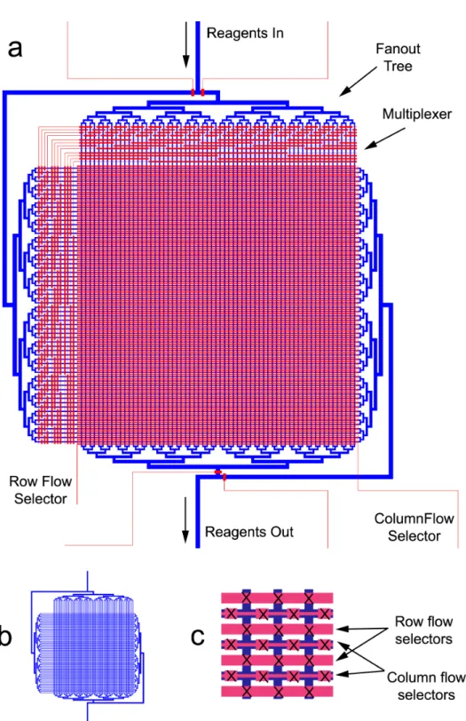
Figure 7.10: Design of an active DNA 6-mer synthesis device. (a) Unlike the passive design of Figure 7.8, in which three different fluidic devices are needed, the active approach requires only a single
device containing a fluid layer (blue) and a control layer (red). Rotation of flow direction is achieved via two banks of valves (dense region in middle), each controlled by a single inlet (row flow selector and column flow selector). Selection of which nucleotides pass through each of the channels is controlled by two multiplexers. Each multiplexer setting opens 16 of the 64 channels through which the current input reagent flows. In each of the 6 steps of 6-mer synthesis, the four nucleotides must be introduced sequentially. Each one will have a different configuration of multiplexer valves to flow the nucleotide through a specific set of 16 channels. However, capping, oxidation, and deprotection steps are performed in all 64 channels simultaneously. The central array is about 1.25 cm on a side. (b) View of the fluid layer alone, as it is obscured by the control layer ina. (c) Detailed view of the array region in the center. The fluid layer consists of a grid of channels (dark blue) crossed by two sets of valves to select row or column flow.
Partially closed valves allow fluid flow but prevent the escape of the beads. In a typical step of synthesis, valves preventing flow in one direction (row or column) would be completely closed. The other valve bank would remain partially closed to hold the beads while reagents were flowed through the columns or rows. (Alternatively, dedicated frit valves or other structures could be incorporated to trap the beads.) Such a device could serve as a massively parallel DNA or peptide synthesizer and products could be cleaved from the beads after synthesis. Alternatively, the chip could be used in array assays by leaving the beads trapped in chambers and flowing the analyte through the microchannels.
7.4.3
Individually-addressable arrays
The microfluidic devices described above are suitable for the synthesis of all possible sequences of a set of monomers.3 It is not possible to synthesize an arbitrary subset of sequences. Flowing reagents along a row causes the same monomer to be added to all product sequences in the row. Therefore, for two sequences to exist on the same row, they must have identical monomers in all positions corresponding to row-wise reactions. The same is true for columns. I wrote a computer program that attempted to optimally place an arbitrary set of sequences in an array of this type, with complete freedom of which monomers flowed in each channel during each step and complete freedom whether each step was to be performed row-wise or column-wise. The main result was that sequences can rarely exist on the same row or column unless the sequences are very highly similar. Other array synthesis techniques, including ink-jet synthesis, light-directed synthesis with mi-cromirror arrays, and robotic synthesis in microtiter plates, are ideally suited to making arrays of arbitrary sequences. Furthermore, these methods are easily reconfigured, meaning that a new set of sequences does not require any equipment modification.
It turns out that one can also fabricate microfluidic synthesis devices with the same degree of flexibility as these approaches. Thorsenet al. [268] demonstrated an individually addressable array device, consisting of an array of chambers that could be selectively purged. Though designed such
3Though I use the word “sequence” implying the synthesis of polymers, this discussion is equally valid for more
general forms of combinatorial synthesis, in which one generates products by a sequence of reactions, not necessarily adding a piece each time, nor necessarily adding new units to the same molecular site.
that chambers were filled one whole row at a time (with the same fluid), a few simple modifications could be made to the design to allow selective loading of chambers as well. The modified chip could be used for combinatorial chemistry if the chambers were open to a derivatized substrate, if the surfaces of each chamber were derivatized with appropriate starting groups, or if the chambers could trap solid support microbeads.
In this hypothetical modification of their design, the introduction of reagents would be a sequen-tial process. First, the first row would be loaded with monomer X, and column valves would be opened in turn for each chamber requiring monomer X at the current position. Next, the second row would be loaded with monomer X and so on until every array element of the chip requiring monomer X at the current sequence position had been reacted.
An alternative design is shown in Figure 7.11, in which all rows in the entire chip can be pre-loaded with a particular reagent. Chambers requiring reaction with the currently pre-loaded reagent are then opened in turn. Each chamber is individually addressable by a row and column valve. Because all rows are preloaded, each reaction cycle can be significantly faster. An additional advantage of this design is that chambers remain sealed if they are not active. Only the active chamber has its double-valves (at its entrance and exit) opened. In contrast, in the design of Thorsenet al., all chambers in a column are opened when a column valve is opened. Though there is flow through only one chamber, valve release in the other chambers leads to the possibility of sample contamination or loss by diffusion or evaporation.
Small modifications to the designs can be made to allow different styles of synthesis. For example, with the inclusion of partially closing valves, synthesis can proceed on trapped solid-support beads. Alternatively, a different valve configuration could allow the double-valves at the inlet and outlet of each chamber to be independently controlled. This would allow reactions requiring solvent-exchange (by evaporation) and would allow accurate metering of reagent volumes by dead-end filling. Synthesized molecules can remain tethered to the substrate or solid-support beads or can be cleaved and purged from the chambers one at a time. Applications other than synthesis are possible with
Figure 7.11:Design and operation of an individually-addressable microfluidic array synthesizer. (Top) Design of the synthesizer. Only a small portion (six reaction sites) are shown for clarity. The fluid channel is shown in blue, and two control layers are shown in red and green. A multi-layer chip architecture could be used to implement this design (see Chapter 6). The blue squares represent reaction chambers. Each chamber is isolated by a double-valve at the bottom (entrance) and top (exit). Valves are indicated by “X”s. In each double-valve, one valve is controlled by a column selector valve, and one is controlled by a row selector valve. Thus the operation is like a BooleanOR-gate: the double-valve remains closed if either the row or column valve is closed (or if both valves are closed). Only if both are opened can fluids flow through the chamber to react with the molecules being “grown” on the substrate by solid-phase synthesis. (Bottom-left) Prior to a reaction step, all row and column selector valves are closed. A reagent is introduced into all fluid channel rows (dark blue). (Bottom-right) To allow the reagent to react with a particular array site, one row selector valve and one column selector valve are opened (indicated by asterisks and lighter colouring). Note the new pattern of “X”s indicating which valves are still closed. A single chamber is opened, allowing fluid to flow through to the output port. Other chambers in the same row or column are still completely isolated by valves. It is not shown in the figure, but row and column selector valves can be controlled via multiplexers as