The
Dimensions Program
Solar Technology Project Laboratory A
Cells
Figure 1 Picture of the Sun taken in Eagan, Minnesota, Courtesy of Arun Kulshreshtha
Project Grant Team
Prof. Chris Oehrlein John S. Pazdar Project Designer Program Director Oklahoma City Community College Asnuntuck Community College
Oklahoma City, Oklahoma Enfield, Connecticut
Patricia L. Hirschy Prof. Carol Tracy Dennis C. Ebersole Principal Investigator Project Tester Principal Investigator Asnuntuck Community College Highland Community College Northampton Community College Enfield, Connecticut Wamego, Kansas Bethlehem, Pennsylvania
Solar Technology – Lab A - 2
Solar Cells
The sun can provide a tremendous source of renewable energy that can be converted to
electricity, heat, and other energy forms. The sun is a continuously burning mass that produces photons, light particles that eventually reach the Earth as sunlight. Even though the sun is 93 million miles away, sunlight can provide up to 1 KW of energy per square yard on Earth.
Sunlight is converted to electricity through solar cells. Solar cells are called photovoltaic (PV) devices because they change light (photons) into electricity (voltage). They are very thin disks (or other shapes cut from disks) sliced from cylinders of silicon that have been manufactured to conduct electricity. When sunlight hits a solar cell, electrons are bumped free. The electrons are channeled into a circuit, and this flow of electrons produces electricity.
Silicon for Solar Cells
A cylinder of silicon, called a boule, is grown by dipping a single crystal of purified silicon into liquefied crystals of silicon and then rotating while slowly pulling it from the melted mixture.
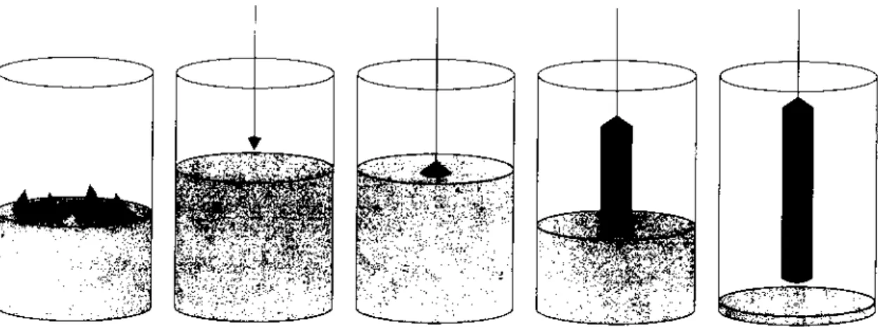
Melting of Introduction of Beginning of Crystal Formed crystal polysilicon, the seed crystal the crystal pulling with a residue
doping growth of melted Silicon
Fig 2 Silicon Monocrystal Fabrication Images Courtesy of Twisp
The boules are grown with diameters between 100 mm and 200 mm (about 4 in – 8 in) and with lengths between 90 cm and 120 cm (about 3 ft – 4 ft).
The silicon atoms in the boule have a diamond cubic structure with each crystal unit taking up the space of a cube with a side length of 0.543 nm.
Fig 3 Model of the Unit Cell of Silicon Courtesy of Ben Mills
Solar Technology – Lab A - 3
Silicon Wafers
Disk-shaped wafers are slice from the boule. Wafers for photovoltaic use are between 200 µm and 300 µm (about 0.008 in – 0.012 in) thick.
mu (µ) is the 12th letter of the Greek alphabet and is equal to 1 micron.
1 micron (µ) = .000001 m or .001 mm Leaders in the semiconductor industry predict that the standard thickness could be 160 µm (about 0.06 in) in the near future. The wafers are then purified, polished, cut into the desired shapes and possibly etched and colored for artistic effect. The finished product is a solar cell. A single solar cell can produce about one-half of a volt of electromotive force.
Fig 4 Wafer Images Courtesy of NASA
As a final step in the process, electrical contacts are attached to the cell. The electrical contacts allow groups of cells to be connected to each other and to the receiver of electrical current produced by the cells when they absorb and convert sunlight.
A group of solar cells arranged inside a rectangular frame and connected by their electrical contacts is called a solar panel. Solar panels are used, for example, to run calculators, to provide energy to homes and businesses and to power satellites.
Fig 5 Solar Panels Attached to Satellites Courtesy of NASA
Solar Technology – Lab A - 4
Quantum Dots
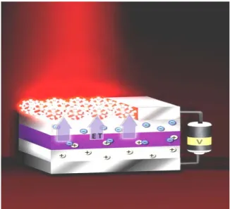
To make solar cells more efficient and more cost-effective, researchers at the University of Toronto are experimenting with technologies that paint, spray or print materials containing tiny bits of semiconducting particles that absorb light onto a conducting glass plate.
These quantum dots have diameters of only 10 nm (about 0.0000004 in). The glass plates are squares with 2.5 cm (about 1 in) side length. Sunlight excites the dots, and the conductive coating on the glass plate collects the electrons freed from the dots as they absorb photons from the sunlight.
The diagram below shows another proposed use of quantum dots. As the dots are excited by an external electromotive force, the separated electrons could be used to produce light when projected through a layer of crystals.
Fig 6 Energy Transfer Diagam
Courtesy of Los Alamos National Laboratory, Marc Achermann
References
Ezine @rticles: http://ezinearticles.com
How Products Are Made: http://www.madehow.com
Northwestern University Qualitative Reasoning Group: http://www.qrg.northwestern.edu Sargent, Edward H., “Connecting the Quantum Dots”, IEEE Spectrum, Vol. 47, February 2010
The
Dimensions Program
Solar Technology Project Laboratory B
Panels
Figure 1 Hubble Space Telescope, Courtesy of NASA
Project Grant Team
Prof. Chris Oehrlein John S. Pazdar Project Designer Program Director Oklahoma City Community College Asnuntuck Community College
Oklahoma City, Oklahoma Enfield, Connecticut
Patricia L. Hirschy Prof. Carol Tracy Dennis C. Ebersole Principal Investigator Project Tester Principal Investigator Asnuntuck Community College Highland Community College Northampton Community College Enfield, Connecticut Wamego, Kansas Bethlehem, Pennsylvania
Solar Technology – Lab B - 2
Panels
Solar panels are manufactured assemblies of solar cells. They are used to convert sunlight into electricity. Solar panels are used by homes and small businesses to provide some or all of their electricity needs at a cheaper rate than conventional, non-renewable sources.
Solar Panels
A solar panel is a packaged and interconnected array of solar cells. The power that a solar panel can generate depends on the number of solar cells (which determines the maximum voltage of the panel) and the current in the electrical circuit to which the cells are connected.
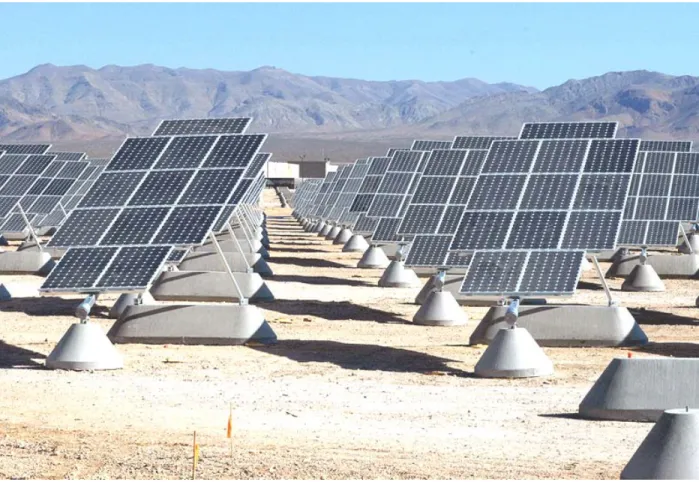
Fig 2 Solar Power Plant
Solar Technology – Lab B - 3
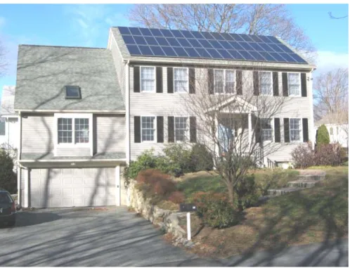
The house, shown in the picture below, uses solar panels to generate over 5,000 watts of power.
Fig 3 Solar House Courtesy of Watson Family
Each of the 48 solar panels can produce 110 watts of power at maximum capacity. Each panel is 653 mm (a little over 2 ft) long, 1,588 mm (a little over 6 ft) tall, and 40 mm (about 1.6 in) thick. The frame around each panel is 18 mm (about 0.7 in) wide.
Fig 4 Solar House Roof Courtesy of Watson Family
Braces connect the solar structure shown above by the top and bottom of each panel that are 264 mm (about 10 in).
Solar Technology – Lab B - 4
Some home and small business owners use solar power to run only a few small systems or appliances. The mini-fridge in the picture below requires 90 watts of power to run for each hour of use.
Each solar panel is constructed of a metal frame that is 585 mm (about 23 in) long, 375 mm (about 15 in) tall and 23 mm (a little less than an inch) thick.
The actual working area containing the solar cells inside each panel is 560 mm (about 22 in) long and 350 mm (about 14 in) tall.
A highly transparent, tempered glass cover is placed over the solar cells in each panel.
The panel is secured to the stand by four screws placed on backside of the panel, 158 mm (about 6 in) from each end along the top and bottom of the frame.
Fig 5 Solar Panel Courtesy of NASA
References
Advanced Power Inc., Weatherford, OK: http://www.apiok.com Answers.com: http://wiki.answers.com
How Products Are Made: http://www.madehow.com Watson Family Solar House: http://256.com/solar
The
Dimensions Program
Solar Technology Project Laboratory C
Heat
Figure 1 Roof Top Solar Collectors,, Courtesy of Department of Energy - NREL
Project Grant Team
Prof. Chris Oehrlein John S. Pazdar Project Designer Program Director Oklahoma City Community College Asnuntuck Community College
Oklahoma City, Oklahoma Enfield, Connecticut
Patricia L. Hirschy Prof. Carol Tracy Dennis C. Ebersole Principal Investigator Project Tester Principal Investigator Asnuntuck Community College Highland Community College Northampton Community College Enfield, Connecticut Wamego, Kansas Bethlehem, Pennsylvania
Solar Technology – Lab C - 2
Solar Collectors
A solar thermal collector is designed to collect heat by absorbing sunlight. Simple collectors are used to heat backyard pools and to heat and cool homes and small businesses. More complex designs use solar heat to generate electricity for power plants and energy-research facilities. Two types of solar collectors are flat plate and evacuated tube.
Flat Plate Collectors
Flat-plate collectors are often used in residential applications. They comprise an insulated box with a transparent top that is angled toward the sun. Inside the box are fluid-filled tubes attached to an absorber plate. The absorber plate is painted black to increase the amount of heat that is absorbed and to decrease the amount of sunlight that is reflected. The sunlight heats the fluid in the tubes. The heated fluid is then transported to an insulated storage tank for future use.
Conventional systems are sometimes added to provide additional temperature control.
In one design, the insulated box has a length of 2,000 mm (about 6 ft), a width of 1,000 mm (about 3 ft) and a thickness of 82 mm (about 3in). The back of the box is made of galvanized steel that is 0.5 mm thick (about 2 hundredths of an in). The sides of the box are made with aluminum that is 57 mm thick (about 2 in). The top of the box is made of glazed, tempered glass that is 4 mm thick (about 16 hundredths of an in).
The inside bottom of the box is covered with glass wool that is 30 mm thick (about 1 in) and has a density of 32 kg/cu m (about 2 lbs/cu ft). On top of the insulation sits a copper-aluminum absorber plate that is 13.8 mm thick (about 1/2 an in). The absorber plate is coated with a black sealant.
The box contains 7 parallel copper tubes, each with diameters of 22 mm (almost an inch). Two perpendicular tubes connect the copper
tubes at each end. An inlet valve is placed through one side of the box, while an outlet valve is placed through the opposite side. The total weight of the box with the thermal collector is 42 kg (about 92 lb).
Fig 2 Flat-Plate Collector Courtesy of Department of Energy
Solar Technology – Lab C - 3
Evacuated Tube Collectors
Evacuated-tube collectors are common in commercial applications. They consist of several cylindrical Pyrex tubes connected and contained in a frame. The cylindrical shape allows
collectors to absorb more energy at a larger range of angles. The tubes are Pyrex and are double-walled. Fluid flows through the U-shaped inner tube to be heated. Air is removed from the space between the inner and outer tubes. The resulting vacuum helps reduce heat loss, thus increasing the efficiency of the collector. Evacuated-tube collectors are useful in moderate or in cold climates. Although evacuated-tube collectors are more effective compared to flat-plate collectors, they currently cost about twice as much.
A typical evacuated-tube design involves an outer tube with a diameter of 58 mm (about 2 in) and a length of 1,800 mm (about 6 ft) long. The inner tube has a diameter of 47 mm (a little more than 1 in) and is coated with a substance that helps maximize the solar radiation and
infrared that is absorbed and converted into heat. A newer method uses a copper heat pipe that is placed inside the evacuated tube structure and an evaporation-condensation method to heat the fluid. The copper heat pipe is 1,750 mm long (about 5 ft) with a diameter of only 8 mm (a little over 1/4 of an in).
Fig 3 Evacuated Tube Collector Courtesy of Department of Energy
An example of an evacuated tube collector available from a company in Michigan contains 20 tubes in a frame that is 1,980 mm long (about 6 ft), 1,650 mm wide (about 5 ft) and 170 mm (about 6 in) thick.
Solar Technology – Lab C - 4
Maximizing Sunlight
The amount of heat delivered from a solar thermal collector depends not only on the efficiency and surface area of the collector, but also on the amount of sunlight. There are several factors affecting sunlight, including geographic location, orientation, and exposure.
Depending on location, the sun’s rays may have a shorter distance to travel (more sunlight) or a longer distance to travel (less sunlight).
Fig 4 Long versus Short Sunrays Courtesy of Peter Halasz
Another factor that affects the amount of sunlight is the Earth’s 23° axial tilt. The most
productive sunlight occurs between 9:00 AM and 3:00 PM, with noon generally being the hottest time of the day.
The Earth’s tilt also produces different seasons, with the summer as the optimal season for sunlight.
Fig 5 Earth’s Axial Tilt
Courtesy of AxialTiltObliquite.png: Dna-webmaster
References
United States Department of Energy, Energy Efficiency and Renewable Energy: http://www1.eere.energy.gov Beijing Sunda Solar Energy Technology Co., Ltd.: http:www.sundasolar.com
The
Dimensions Program
Solar Technology Project Laboratory D
Power
Figure 1 National Solar Thermal Test Facility, Courtesy of Sandia National Laboratory – Albuquerque, NM
Project Grant Team
Prof. Chris Oehrlein John S. Pazdar Project Designer Program Director Oklahoma City Community College Asnuntuck Community College
Oklahoma City, Oklahoma Enfield, Connecticut
Patricia L. Hirschy Prof. Carol Tracy Dennis C. Ebersole Principal Investigator Project Tester Principal Investigator Asnuntuck Community College Highland Community College Northampton Community College Enfield, Connecticut Wamego, Kansas Bethlehem, Pennsylvania
Solar Technology – Lab D - 2
Concentrating Solar Power Systems
Solar energy is attractive to large-scale users such as business and industry for economic and efficiency reasons. Concentrating solar power systems are used to meet the enormous energy demands of a power plant. Two main types of concentrating solar power systems are power tower systems and linear concentrator systems.
Power Towers
Power tower technology uses a large number of sun-tracking mirrors, called heliostats, to reflect sunlight onto a receiver at the top of a tower. Fluid in the receiver is converted to steam that is used to power a turbine, producing electricity.
Fig 2 Power Tower Power Plant Courtesy of NREL
Gemasolar, a planned power tower in Spain, will be 130 m high (about 425 ft). There will be 2,590 heliostats
focused at the top of the tower. Each heliostat will contain sixteen square mirrors, each with a side length of 2.6 m (about 8 ft). There will be 5 cm (a little less than 2 in) of space between each mirror.
A 100,000 Heliostat power tower plant is being planned for the Mojave Desert. It will cover an area of 1,600 hectares (almost 4,000 acres).
Fig 3 Power Tower
Solar Technology – Lab D - 3
Linear Concentrators
A linear concentrator system consists of an assembly of long rows of reflective devices
positioned to reflect sunlight onto long glass or transparent plastic evacuated tubes. The liquid or gas is heated as it flows through the tubes and into insulated storage tanks. The two major types of linear concentrators systems are parabolic trough systems and linear Fresnel reflector systems.
Parabolic Trough
In parabolic trough systems, the tubes are placed along the middle of
parabolic-shaped mirrors.
Fig 4 Linear Concentrator Power Plant Courtesy of Dept of Energy - EERE
One of the most successful parabolic trough solar power plants is in the Kona desert in Hawaii. It uses 1,000 mirrors arranged into 50 rows. Each mirror is 3.66 m (about 12 ft) and has a surface area of 5.07 sq m (about 54 sq ft).
A mirror occupies a space that is 1.52 m (about 5 ft) wide. When arranged in rows, the distance between glass tubes in adjacent rows is 2.14 m (about 7 ft). This facility generates 2 MW of power.
Fig 5 Linear Concentrator
Courtesy of Department of Energy - NREL
Linear Fresnel Reflector
In linear Fresnel (pronounced “fray-nel”) systems, the mirror lens may be slightly curved or completely flat. The receiver tube is placed above multiple rows of mirrors that are set at an optimal angle to allow flexibility in tracking the sunlight.
These mounted tubes may have small parabolic mirrors attached slightly above and behind them to re-reflect light that misses the tube. This design is more cost-effective than parabolic troughs. It uses fewer evacuated tubes, and there is much less space needed between rows of (almost) flat, slightly tilted mirrors.
Solar Technology – Lab D - 4
The Puerto Errado 1 Thermosolar Power Plant in southern Spain is a prototype Fresnel facility that has been running since May 2009. It consists of two lines of Fresnel mirrors. Each line has 16 rows of mirrors. Each row is 985.6 m (about 1,078 yd) long and contains 176 mirrors that are each 1.4 m (about 4 ft) wide.
Fig 6 Linear Fresnel Technology, Courtesy of NOVATEC BIOSOL
With all of the mirrors positioned at the same angle, a row occupies a width of 1 m (a little over 1 yd). This plant produces 1.4 MW of power. Based on the success of this test facility,
construction of Puerto Errado 2 has begun. It will be more than seven times the size of the prototype plant, and will generate close to 30 MW of power – the equivalent of 49 million kg of greenhouse gases from gas or coal-fired power plants.
Solar Technology
Solar technology including cells, panels, collectors, and other devices is designed to harness the energy of sunlight and apply it to meet the needs of our world. Solar energy can be used to light a home, to heat a pool, to run an industrial plant, or to power satellites. It is a new field that will grow in importance as technological discoveries continue to advance its applications.
References
Martin, Jose C., “Solar Tres”, National Renewable Energy Laboratory Concentrating Solar Power Technology Workshop, March 2007 National Renewable Energy Laboratory: http://www.nrel.gov
Net Resources International: http://www.power-technology.com NOVATEC BIOSOL AG: http://www.novatec-biosol.com Sopogy Total Solar Solutions: http://www.sopogy.com