1
1 Introduction ... 3
2 The Basics of Serial Bus Systems ... 4
2.1 Applications and Definitions ... 4
2.2 Basic Functions of Bus Systems ... 5
2.2.1 Access Techniques ... 6
2.2.2 Synchronization of Participants... 7
2.2.3 Error Processing ... 7
2.3 The OSI Reference Model ... 8
3 Overview of the M-Bus ... 11
3.1 Requirements of a Bus System for Consumer Utility Meters ... 11
3.2 The M-Bus in the OSI Model... 11
4 Physical Layer ... 14
4.1 Principles of Operation ... 14
4.2 Specifications for Bus Installations... 16
4.3 Specifications of the Repeaters ... 17
4.4 Slave Design ... 17
5 Data Link Layer ... 21
5.1 Transmission Parameters ... 21
5.2 Telegram Format... 22
5.3 Meaning of the Fields ... 23
5.4 Communication Process... 25
5.5 FCB- and FCV-Bits and Addressing... 27
5.5.1 Applications of the FCB-mechanism ... 27
5.5.2 Implementation aspects for primary addressing ... 28
6 Application Layer... 31
6.1 CI-Field ... 31
6.2 Fixed Data Structure ... 34
6.3 Variable Data Structure... 36
6.3.1 Fixed Data Header ... 36
6.3.2 Variable Data Blocks... 37
6.3.3 Manufacturer Specific Data Block ... 43
6.4 Configuring Slaves... 45
6.4.1 Switching Baudrate... 45
6.4.3 Configuring Data Output ... 48
6.5 Generalized Object Layer... 51
6.6 Application Layer Status... 53
6.7 Special Slave Features ... 55
6.7.1 Auto Speed Detect ... 55
6.7.2 Slave Collision Detect ... 56
6.7.3 Use of the Fabrication Number ... 57
6.7.4 Hex-Codes $A-$F in BCD-Data Fields... 57
7 Network Layer... 63
7.1 Selection and Secondary Addressing ... 63
7.3 FCB-Bit and Selection ... 64
7.4 Searching for Installed Slaves ... 65
7.4 Generalized Selection Procedure ... 69
8 Appendix ... 70
8.1 Alarm Protocol... 70
8.2 Coding of Data Records ... 71
8.3 Tables for Fixed Data Structure ... 74
8.3.1 Measured Medium Fixed Structure ... 74
8.3.2 Table of Physical Units... 75
8.4 Tables for Variable Data Structure ... 76
8.4.1 Measured Medium Variable Structure ... 76
8.4.2 Data Field Codes ... 77
8.4.3 Codes for Value Information Field (VIF)... 78
8.4.4 Extension of primary VIF-Codes... 80
8.4.5 Codes for Value Information Field Extension (VIFE) ... 84
3
1 Introduction
This document, which is based on references [11] and [12], gives detailed and actual information about the M-Bus,which is a low cost home electronic system (HES).
This documentation about the M-Bus is published by the M-Bus Usergroup, which is an international organization of users and producers of M-Bus devices. The usergroup meets several times a year to discuss problems and developments in hardware and software. Recommendations, agreements, examples and explanations are included in this paper as well as parts of the standards itself. Among other things the actual version of this document in Winwordformat can be downloaded from the M-Bus Mailbox.
M-Bus Usergroup: Prof. Dr. Horst Ziegler Fachbereich Physik Universität-GH Paderborn Warburgerstr. 100 Germany 33098 Paderborn Phone: +49 5251 / 602735 WWW: http://fb6www.uni-paderborn.de/M-Bus/ M-Bus Mailbox: Phone: +49 5251 / 603830 Parameter: 300..14400 bps, 8N1 Sysop: Carsten Bories, Phone 602750
The M-Bus (Meter Bus) was developed to fill the need for a system for the networking and remote reading of utility meters, for example to measure the consumption of gas or water in the home. This bus fulfills the special requirements of remotely powered or battery driven systems, including consumer utility meters. When interrogated, the meters deliver the data they have collected to a common master, which can, for example, be a hand-held computer, connected at periodic intervals to read all utility meters of a building. An alternative method of collecting data centrally is to transmit meter readings via a modem.
Other possible applications in home electronic systems for the M-Bus are alarm systems, flexible illumination installations and heating controlling.
REMARKS:
♣ Text parts or topics marked with this symbol are new or changed information since last version 4.7.1 of this document.
2 The Basics of Serial Bus Systems
2.1 Applications and Definitions
The methods by which data processing systems communicate with each other are classified according to the distances involved. With world-wide networks the term used is Global Area Networks (GAN), whereas networks covering continents or large land masses are known as Wide Area Networks (WAN); Local Area Networks (LAN) are concerned with distances up to a few kilometers, and are limited to specific geographical areas, such as laboratories, office buildings and company premises. Such local networks are used, for example, to link terminals, computers, measuring equipment and process automation modules with one another.
In the majority of local networks, one or other of the following methods (topologies) are used to link the components in a system:
• Star Topology
Each component is linked to a central processor unit with an individual transmission line. The equipment can transmit to the central unit either sequentially or simultaneously. One disadvantage of this arrangement is the increased requirement for cabling.
• Ring Topology
In this case, the components are connected to one another in a ring, and the data are transferred from point to point. This topology has the disadvantage that, should a single equipment fail, the complete network will be out of action.
• Bus Topology
The components are connected together with a common transmission line, with the result that at one instant only one equipment can transmit data. This topology is very cost-effective, it will not be disturbed if one of the components fails, and it allows the transmission of data to all components (Broadcasting) or to specific groups in the system (Multicasting).
Star Ring Bus
2.2 Basic Functions of Bus Systems 5
A serial bus can be defined as a transmission path over which the participants transmit their data serially (i.e. bit after bit), sequentially in time and using a common medium. In contrast, in parallel bus systems the individual bits which form a character are transmitted simultaneously by a certain number of data lines. This results in increased costs for cable and connectors; the transmission time is shorter than with a serial bus.
2.2 Basic Functions of Bus Systems
The following diagram is intended to provide an overall view of the various forms of serial bus systems:
Serial Bus
Time Division Multiplex Frequency Multiplex
Synchronous Assynchronous One Subscriber Several Subscribers
Transmission per Channel per Channel
with central control
Controlled Bus Uncontrolled Bus
Access Access
Central Bus Decentral Bus Carrier Sense Carrier sense
Allocation Allocation with collision recognition Transmission
Fig. 2 Classification of Serial Bus Systems According to Transmission and Access
Techniques [1]
The first subdivision can be made according to the multiplex technique which is used. With frequency multiplex, the frequency spectrum of the transmission medium is divided into frequency bands, each representing a channel. Each participant is then allocated a channel. In the next section, the kind of synchronization and access techniques which are used will be described in order to classify serial bus systems using time division multiplex.
2.2.1 Access Techniques
Since in bus systems the transmission medium is used by all participants together, account must be taken of their various transmission requirements. The methods used by participants who want to transmit over the bus are known as access techniques. These techniques must ensure that several stations do not transmit simultaneously, and so cause bus conflicts or collisions, and that each participant can transmit for at least a certain minimum time. The sharing of the bus among stations who want to transmit is implemented with an allocation logic system.
With central allocation logic, the central bus controller receives a request to use the bus and then takes the decision as to whether, and if so when, the user can occupy the bus. For this purpose various methods are used to register the bus occupation request:
• direct registration by means of an individual branch line to each equipment
• periodical interrogation (polling) of the participants as to their transmission needs
• requests sent on a common line with identification of the sender
• allocation of the bus according to a predetermined time frame without taking account of individual requirements
The advantage of central allocation logic is the reduced complexity which is required at individual stations.
With decentralized allocation logic, each participant is provided with functions which allow him to recognize whether the bus is already in use. There are various methods which can be used to determine whether the bus is occupied:
• mutual interrogation of stations by means of a request line for each station
• periodical bus allocation, by passing "ownership" of the bus from station to station
• CSMA (Carrier Sense Multiple Access): The participants have the ability to check whether the bus is transmitting data, and to transmit their own data if it is found to be free. To avoid collisions, which could arise as a result of signal transit times, with certain bus systems (e.g. Ethernet) the stations are able to use their own data on the bus to determine whether there is a bus conflict. In such a case, the transmission will be interrupted and repeated after an appropriate time interval.
2.2 Basic Functions of Bus Systems 7
A higher degree of logic complexity at each station is needed to implement decentralized allocation logic, but this system also has the advantage that a fault in the central bus controller will not result in a complete breakdown of the bus.
2.2.2 Synchronization of Participants
Synchronization is to be understood as the coordination in time of the communicating participants, with regard to signal transmission and reception. The various methods of synchronization can be classified into data transmission which is synchronous and that which is asynchronous (see Figure 3).
With synchronous transmission, a stable clock signal is supplied either by the central station or one of the communicating partners, which serves to measure transmission times. With asynchronous transmission, a distinction must be made between techniques with and without signal acknowledgment. Where there is signal acknowledgment (handshake), the sender shows with a specific signal on the line that he has data to send, and waits for an acknowledgment from the receiver. Techniques without acknowledgment use a transfer clock on a special line for parallel bit transmission, or start and stop bits to frame a character for bit-serial transmission. Synchronization Synchronous Transmission (clock signal) Without Acknowledgement With Acknowledgement (Handshake) Start-Stop Bits Asynchronous Transmission Transfer Clock
Fig. 3 Classification of Synchronization Techniques
2.2.3 Error Processing
The reasons for transmission errors in bus systems are widely known. These include in particular electromagnetic interference from outside, for example: inductive coupling at mains frequencies; high-frequency interference as a result of sparking at the brushes of motors or arcs of discharge lamps; capacitive coupling to other lines; or directly coupled currents from ground loops as a result of multiple grounds.
A bus system must ensure that transmission errors are recognized and corrected. For this reason additional information is supplied with the data to be transmitted, which allows the data to be checked on reception.
Particularly with asynchronous transmission, an additional parity bit is often transmitted with each character. This parity bit is constructed so that the parity conditions (an even number of ones, or an odd number of ones) are fulfilled. Another method is the creation of a block check character from specific mathematical operations e.g. addition without carry (Check Sum), which is derived from all the data. The receiving station can detect whether there have been transmission errors by comparing the check character it has received with one which it has calculated itself. The parity bit allows only the recognition of an odd number of faulty bits. In order to correct errors the recipient sends an acknowledgment, which indicates that the transmission has been either error free, or that there have been transmission errors. For the same purpose the transmitter checks that the receiver acknowledges the reception of data in a certain period of time. If the time limit is exceeded (Timeout), or if a transmission error has been reported, then the sender repeats the transmission a predetermined number of times. The Hamming Distance is used in order to specify the security of a character code; this is the number of errors (minus one) which can be recognized for all cases.
2.3 The OSI Reference Model
The ISO-OSI reference model provides a basis for the development of standards for Open Systems Interconnection (OSI). This model devised by the "International Organization for Standardization" (ISO) is intended to ensure that information from systems made by various manufacturers, and having different architecture, can be exchanged and interpreted in accordance with standardized procedures.
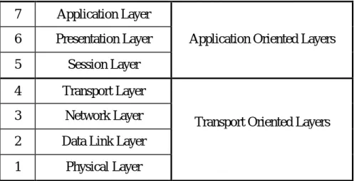
This model arranges the communications functions in seven layers, each of which has a virtual connection to the appropriate layer of the communicating partner. Only on the lowest layer (Layer 1) is there a physical connection for exchanging signals. Each layer, with the exception of Layer 1, obtains the necessary service from the layer below it. The OSI model merely defines the servicing and functions of the layers, but not the technical realization (the protocols) within the layers.
Two user programs can exchange information on Layer 7, if there is agreement between them (i.e. there are protocols) on the following points [2]:
• the representation of information in Layer 6
• the flow of communications (contents and form) in Layer 5
• the completeness of the information and the security of transport in Layer 4
2.3 The OSI Reference Model 9
• the security of transmission in Layer 2
• the physical medium in Layer 1 7 Application Layer
6 Presentation Layer Application Oriented Layers
5 Session Layer
4 Transport Layer
3 Network Layer
Transport Oriented Layers 2 Data Link Layer
1 Physical Layer
Fig. 4 The Seven Layers of the OSI Model
The functions of the individual layers shown in Figure 4 will now be explained in more detail: Physical Layer
The basic physical connection between the communicating partners takes place in this lowest layer. The mechanical and electrical coupling to the transmission medium is determined here, by specifying (among other things) the cable, the distances involved, the pinning of connectors, and the way the bits are represented.
Data Link Layer
This layer is responsible for assuring that a reliably operating connection is made between two participants. For this purpose the protocol of this layer determines the methods for protecting transmissions, the telegram structure, methods of accessing the transmission medium and for the synchronization and addressing of participants. By making use of the procedures described in Section 2.2.3 it should be possible to identify and correct faults in the Data Link Layer. Network Layer
The network layer undertakes the choice and implementation of the best transmission route in a network between the communicating parties, and provides this service (Routing) to the Transport Layer. This function is of particular significance when different networks need to be connected by means of Gateways.
Transport Layer
The transport layer represents the boundary between the application oriented layers 5 to 7, and the transport oriented layers 1 to 4. Its job includes guiding the information through the network, controlling the flow of information and the grouping into individual packets.
Session Layer
The session layer provides procedures for the opening, the orderly progressing, and the termination of a communication "session". In this is included also the control of the dialogue between systems: that is, the determination of their respective transmission prerogatives. Presentation Layer
The data of the application are converted in the presentation layer into a data format which the receiving application can interpret. This layer thus implements the matching of data formats and the conversion of codes.
Application Layer
This top layer represents the interface between the open system and the user. It offers the user or his program a service allowing him to work easily with the system. Application programs which need to be developed can thus access the functions of the open system via the protocol of the application layer.
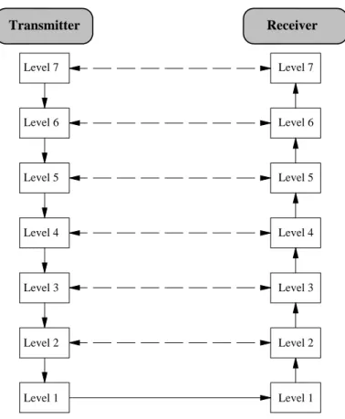
In the following diagram the route to be followed by data from the transmitting to the receiving application can be seen, indicated by the continuous arrows. At the transmitting side information (Overhead) which is necessary for transmission and processing is added to the actual data in each layer; at the receiving side this information is removed again in the reverse order after processing.
Level 7 Level 7 Level 6 Level 5 Level 4 Level 3 Level 2 Level 1 Level 1 Level 2 Level 3 Level 4 Level 5 Level 6 Transmitter Receiver
3.1 Requirements of a Bus System for Consumer Utility Meters 11
3 Overview of the M-Bus
3.1 Requirements of a Bus System for Consumer Utility Meters
Of the various possible topologies which might be considered for reliable and cost-effective networking consumer utility meters, only the bus topology (see Section 2.1) is in fact suitable. The requirements which are made by meters on such a bus system will now be explained. The most important requirement is the interconnection of many devices (several hundred) over long distances - up to several kilometers. Since the data sent by the meters are used for end user billing, a high degree of transmission integrity is required for the bus. On the other hand it is possible to dispense with high speed of transmission, since usually only a relatively small amount of information must be transferred. To ensure this high degree of transmission integrity, the bus must be exceptionally insensitive to external interference, as a result of capacitive or inductive coupling. In order to avoid ground loops, the slave should be electrically isolated.
A further requirement for the bus is low cost for the complete system. The transmission medium which is used should therefore not require shielding, and the cost of individual meters can be minimized by using as few components as possible and by remotely powering the slaves from the bus. In addition the costs of installing and servicing the system must be taken into account: These can be reduced by incorporating protection against reversed polarity, and making provision for the connection of additional facilities (Life Insert) during operation of the bus system.
3.2 The M-Bus in the OSI Model
Since no bus system was available which met the requirements detailed in Section 3.11, the Meter-Bus (M-Bus) was developed by Professor Dr. Horst Ziegler of the University of Paderborn in cooperation with Texas Instruments Deutschland GmbH and Techem GmbH. The concept was based on the ISO-OSI Reference Model, in order to realize an open system which could utilize almost any desired protocol.
Since the M-Bus is not a network, and therefore does not - among other things - need a transport or session layer, the levels four to six of the OSI model are empty. Therefore only the physical, the data link , the network and the application layer are provided with functions.
1
Layer Functions Standard Chapter
Application
Data structures, data types,
actions EN1434-3 6
Presentation empty
Session empty
Transport empty
Network extended addressing (optional) - 7
Data Link
transmission parameters, telegram
formats, addressing, data integrity IEC 870 5 Physical
cable, bit representation, bus extensions,
topology, electrical specifications. M-Bus 4
Fig. 6 The M-Bus layers in the OSI-Model
Because changing of parameters like baudrate and address by higher layers is not allowed in the ISO-OSI-Model, a Management Layer beside and above the seven OSI-Layers is defined: MANAGEMENT LAYER Application Layer Presentation Layer Session Layer Transport Layer
Network Layer (if address = 253) Address 253 / Enable Disable CI=$52/$56 Data Link Layer
Physical Layer Address 254 (255)
3.2 The M-Bus in the OSI Model 13
So the address 254 and perhaps 255 are reserved for managing the physical layer and the address 253 (selection) for network layer (see chapter 7), which is only used in certain cases. With this new layer we can directly manage each OSI-layer to implement features, which do not conform to the OSI-Model.
4 Physical Layer
More and detailed informations about the specifications of the physical layer are listed in the document 'WG4N85R2.DOC' ♣.
4.1 Principles of Operation
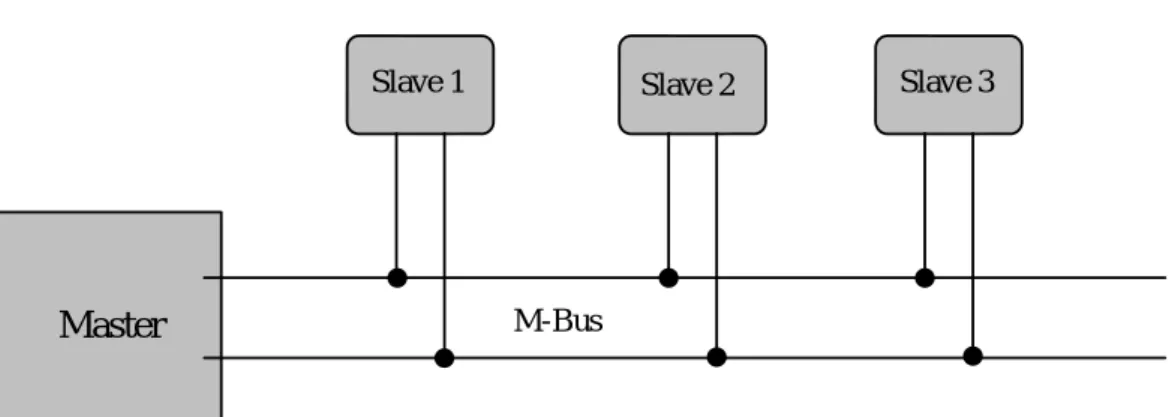
The M-Bus is a hierarchical system, with communication controlled by a master (Central Allocation Logic). The M-Bus consists of the master, a number of slaves (end-equipment meters) and a two-wire connecting cable: see Figure 8. The slaves are connected in parallel to the transmission medium - the connecting cable.
Master
Slave 2 Slave 3
Slave 1
M-Bus
Fig. 8 Block diagram showing principle of the M-Bus System
In order to realize an extensive bus network with low cost for the transmission medium, a two-wire cable was used together with serial data transfer. In order to allow remote powering of the slaves, the bits on the bus are represented as follows:
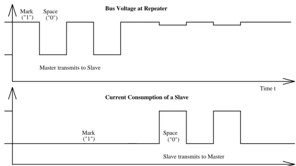
The transfer of bits from master to slave is accomplished by means of voltage level shifts. A logical "1" (Mark) corresponds to a nominal voltage of +36 V at the output of the bus driver (repeater), which is a part of the master; when a logical "0" (Space) is sent, the repeater reduces the bus voltage by 12 V to a nominal +24 V at its output.
Bits sent in the direction from slave to master are coded by modulating the current consumption of the slave. A logical "1" is represented by a constant (versus voltage, temperature and time) current of up to 1.5 mA, and a logical "0" (Space) by an increased current drain requirement by the slave of additional 11-20 mA. The mark state current can be used to power the interface and possibly the meter or sensor itself.
4.1 Principles of Operation 15 Ispace = Imark Imark < 1,5mA + (11-20) mA Vmark = 36 V Vspace = 24 V
Master transmits to Slave
Bus Voltage at Repeater
Current Consumption of a Slave
Time t
Time t Slave transmits to Master
Mark ("1") Space ("0") Mark ("1") Space ("0")
Fig. 9 Representation of bits on the M-Bus
The transmission of a space by a slave results in a slight reduction in the bus voltage at the repeater due to output impedance, as can be seen in Figure 9.
The quiescent state on the bus is a logical "1" (Mark), i.e. the bus voltage is 36 V at the repeater, and the slaves require a maximum constant quiescent current of 1.5 mA each.
When no slave is sending a space, a constant current will be drained from the repeater which is driving the bus. As a result of this, and also the resistance of the cable, the actual Mark voltage at the slaves will be less than +36 V, depending on the distance between the slave and the repeater and on the total quiescent current of the slaves. The slave must therefore not detect absolute voltage levels, but instead for a space detect a voltage reduction of 12 V. The repeater must adjust itself to the quiescent current level (Mark), and interpret an increase of the bus current of 11-20 mA as representing a space. This can be realized with acceptable complexity only when the mark state is defined as 36 V. This means that at any instant, transmission is possible in only one direction - either from master to slave, or slave to master (Half Duplex).
As a result of transmission in the master-slave direction with a voltage change of 12 V, and in the answering direction with at least 11 mA, besides remote powering of slaves a high degree of insensitivity to external interference has been achieved.
4.2 Specifications for Bus Installations
SegmentationAn M-Bus system can consist of several so-called zones, each having its own group address, and interconnected via zone controllers and higher level networks. Each zone consists of segments, which in turn are connected by remote repeaters. Normally however, an M-Bus system consists of only a single segment, which is connected via a local repeater to a Personal Computer (PC) acting as master. Such local repeaters convert the M-Bus signals into signals for the RS232 interface. From now on, the local repeater will simply be termed the "repeater", and the combination of PC and local repeater termed the "master".
Cable
A two-wire standard telephone cable (JYStY N*2*0.8 mm) is used as the transmission medium for the M-Bus. The maximum distance between a slave and the repeater is 350 m; this length corresponds to a cable resistance of up to 29 Ω. This distance applies for the standard configuration having Baud rates between 300 and 9600 Baud, and a maximum of 250 slaves. The maximum distance can be increased by limiting the Baud rate and using fewer slaves, but the bus voltage in the Space state must at no point in a segment fall below 12 V, because of the remote powering of the slaves. In the standard configuration the total cable length should not exceed 1000 m, in order to meet the requirement of a maximum cable capacitance of 180 nF.
Plug
There is so far no standard or recommendation for a M-Bus plug to connect the meters to the bus system, but the Usergroup investigates in defining a proper connector. Three different plugs have to be defined for the connector at a) the installation mode b) meter to fixed installation and c) meter to handheld connection.
4.3 Specifications of the Repeaters 17
4.3 Specifications of the Repeaters
See chapter 'Electrical Requirements Master' in the document 'WG4N85R2.DOC' ♣.
4.4 Slave Design
The requirements for slaves are listed in the paper 'WG4N85R2.DOC' ♣. The following characteristics are part of it:
• Transmission Characteristics
The slaves are designed to be constant current sinks with two different currents, whereby the current which is "sunk" must not vary by more than 0.2 % for 1 V voltage change on the bus. In order to transmit a Mark, a so-called Unit Load consisting of a constant current of 1.5 mA maximum is specified. If the slave needs more current, an appropriate number of additional Unit Loads must be used. When sending a Space, the slave increases its current consumption by 11-20 mA. In order to receive data, the slave detects the maximum value Vmax of the bus voltage, which can be between 21 V and 42 V. With a bus voltage of more than Vmax - 5.5 V, a Mark should be registered, and with a voltage of less than Vmax - 8,2 V, a Space should be registered.
• Remote Powering
The bus interface - that is, the interface between the slave and the bus system - must take the current it needs from the bus system. If possible, the complete slave should be fed from the bus; in this case, should the bus fail, it must automatically switch over to battery operation, or the significant data must be saved. If the slaves are operated only from batteries, it is necessary that a battery life of several years should be attained, in order to reduce maintenance costs.
• Protective Measures
The bus interfaces of the slaves are polarity independent: that is, the two bus lines can be interchanged without affecting the operation of the slaves. Besides protection aspects, this also results in simplified installation of the bus system. In order to maintain correct operation of the bus in case of a short circuit of one of the slaves as metioned before these must have a protection resistor with a nominal value of (430±10)Ωin their bus lines. This limits the current in the case of a short circuit to a maximum of 100 mA (42 V / 420 Ω), and reduces the energy converted into heat in the bus interface.
M-Bus Transceiver TSS721
In order to meet the requirements for the slaves mentioned above, an IC was developed by Texas Instruments Deutschland GmbH, namely the Transceiver (i.e. Transmitter and Receiver) TSS721. The use of the TSS721 in M-Bus slaves as the interface to the bus reduces the number of components needed, and therefore the cost of slaves. Apart from the transmission and reception of data in accordance with the M-Bus specification, this IC also provides translation from and to the operating voltage of the microprocessor to which it is connected, in order to be able to communicate with it. The communication can take place at baudrates from 300 to 9600 Baud. Additional features include integrated protection against reversed polarity, a constant 3.3V power supply for the microprocessor, and the prompt indication of failure of the bus voltage.
By referring to Figure 10, the individual functions of the TSS721 will now be explained in more detail:
Fig. 10 Block Diagram of the Transceiver TSS721 [4]
• Reversed Polarity Protection
The bus lines are first taken to the bridge rectifier BR via the external protection resistors Rv (in this case, of 215Ω in each line), in order to provide reversed polarity protection. This rectified voltage can be accessed at the VB (Voltage Bus) pin. In order the avoid a reduction of the voltage as a result of rectification, when reversed polarity protection can
4.4 Slave Design 19
be dispensed with, the bus voltage may also be connected directly between the VB and GND pins.
• Reception
The comparator circuit TC3 is provided to detect signals from the master; it adjusts itself to the Mark voltage level with the help of the capacitor SC. This capacitor is charged up to 8.6 V under the Mark voltage when in the Mark state, and discharged during the Space state. The ratio of charge to discharge current is more than 30 to make any kind of UART protocol work indepedently of the data contents. The voltage across the capacitor SC results in dynamic matching of the comparator to the Mark level. From the relationship between the charging and discharging current results the requirement in the transmission protocol that at least every eleventh bit (with adequate certainty) must be a logical 1 - that is, a Mark. This guarantees that SC is not discharged too much, and that matching to the Mark voltage level is always effective. With a voltage of 7.9 V under the Mark level, the TSS721 gives a logical 0 to the TX pin (0 V) and to the inverted TXI pin (Supply Voltage).
• Transmission
The signal from the microprocessor applied to the RX Pin or RXI Pin (inverted) is converted into a current by TC4 and the constant current source CS3. When there is a Mark at the inputs (RX or RXI), the quiescent current is taken from the bus with the help of the constant current source. If however the processor transmits a Space, then TC4 switches on the constant current source CS3, and consequently the additional pulse current. The quiescent current can be adjusted over a certain range with the resistor Ridd, and the pulse current adjusted with Ris. In order to allow the processor to recognize collisions, the signal on the RX(I) pins is echoed on the TX(I) pins.
• Powering of the Processor
The TSS721 provides a nominal voltage of 3.3 V at its VDD Pin, in order to supply power to a microprocessor. When limited to a standard load, according to the data sheet this processor may however consume an average current of about 600 µA. For pulse current requirements, use is made of the reservoir capacitor STC. When connection is made to the bus, this capacitor will be charged at up to 7 V, and the power supply at the VDD pin is activated at VSTC= 6 V. The TSS721 signals the failure of the bus voltage at the PF-Pin (power fail), so that the processor has time to store its data in e.g. an EEPROM, whilst powered by the reservoir capacitor. In addition, the transceiver permits the connection of a battery to the VDD Pin should the bus fail, by means of FET at the VS Pin (voltage switch). In such a case, and when the microprocessor is powered solely with a battery, the voltage must also be taken to the BAT Pin in order to match into the TSS721.
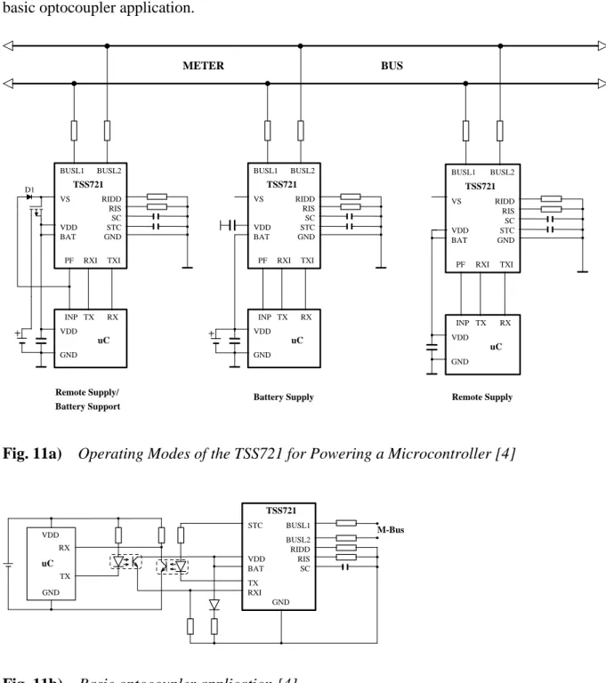
Figure 11a) shows three alternative operating modes for the TSS721 which can be used to power a microprocessor. It shows that the processor can be supplied exclusively by the transceiver (remote supply), normally from the TSS721 and with bus failure from a battery (remote supply/battery support), or only by the battery. Few external components are needed to build a complete slave with the TSS721, apart from the microprocessor or microcontroller and the components specifically required for the sensing elements. Besides Fig. 11b) shows a basic optocoupler application.
BUSL1 VS VDD BAT PF RXI TXI BUSL2 RIDD RIS SC STC GND TSS721 VDD GND INP TX RX uC BUSL1 VS VDD BAT PF RXI TXI BUSL2 RIDD RIS SC STC GND TSS721 VDD GND INP TX RX uC BUSL1 VS VDD BAT PF RXI TXI BUSL2 RIDD RIS SC STC GND TSS721 VDD GND INP TX RX uC METER BUS D1 Remote Supply/ Battery Support
Battery Supply Remote Supply
Fig. 11a) Operating Modes of the TSS721 for Powering a Microcontroller [4]
VDD BAT RXI TX RIDD RIS SC GND TSS721 M-Bus BUSL1 BUSL2 STC RX TX VDD GND uC
5.1 Transmission Parameters 21
5 Data Link Layer
The physical layer makes certain demands on the data link layer. Besides half-duplex asynchronous serial transmission with data rates between 300 and 9600 Baud, these include the requirement that at least every eleventh bit should be a logical 1, and also that there should be a Master-Slave structure, since the slaves can not communicate with each other.
The protocol of the data link layer is based on the international standard IEC 870-5, which defines the transmission protocols for telecontrol equipment and systems. The M-Bus protocol described below derives from the above standard, but doesn´t use all the IEC functions.
The signal quality requirements for master and slaves are listed in the document 'WG4N86R2.DOC' ♣ (available in the mailbox and via internet). It is based on the international standard IEC 7480.
5.1 Transmission Parameters
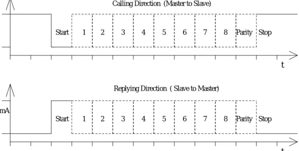
This protocol uses asynchronous serial bit transmission, in which the synchronization is implemented with start and stop bits for each character. There must be no pauses within a telegram, not even after a stop bit. Since quiescence on the line corresponds to a 1 (Mark), the start bit must be a Space, and the stop bit a Mark. In between the eight data bits and the even parity bit are transmitted, ensuring that at least every eleventh bit is a Mark. The bits of data are transmitted in ascending order, i.e. the bit with the lowest value (LSB = least significant bit) is the first one to be found on the line. The transmission takes place in half duplex and with a data rate of at least 300 Baud. In Figure 12, the transmission of a byte in calling and replying direction is represented.
Start 1 2 3 4 5 6 7 8 Stop Start 1 2 3 4 5 6 7 8 Stop - 12 V Imark Imark + (11-20)mA t t Vmark Vmark
Calling Direction (Master to Slave)
Parity
Parity Replying Direction ( Slave to Master)
5.2 Telegram Format
According to IEC 870-5, three different data integrity classes (I1, I2 and I3) are envisaged for the transmission of remote control data. The data integrity class is a measure of the quotient between the rate of undetected false messages and the probability of faulty bits during transmission. For the data integrity classes mentioned above, various format classes have been identified, in which measures to recognize transmission faults are defined. For the M-Bus protocol of the data link layer the format class FT 1.2 is used, which is contained in the data integrity class I2, which specifies a Hamming Distance of four.
The format class FT 1.2 specifies three different telegram formats, which can be recognized by means of special start characters. Below, and in figure 13, the telegram formats used for the M-Bus will now be explained.
Single Character Short Frame Control Frame Long Frame
E5h Start 10h Start 68h Start 68h
C Field L Field = 3 L Field
A Field L Field = 3 L Field
Check Sum Start 68h Start 68h
Stop 16h C Field C Field
A Field A Field
CI Field CI Field
Check Sum User Data
Stop 16h (0-252 Byte)
Check Sum Stop 16h Fig. 13 Telegram Formats of the M-Bus Protocol
• Single Character
This format consists of a single character, namely the E5h (decimal 229), and serves to acknowledge receipt of transmissions.
• Short Frame
This format with a fixed length begins with the start character 10h, and besides the C and A fields includes the check sum (this is made up from the two last mentioned characters), and the stop character 16h.
5.3 Meaning of the Fields 23
• Long Frame
With the long frame, after the start character 68h, the length field (L field) is first transmitted twice, followed by the start character once again. After this, there follow the function field (C field), the address field (A field) and the control information field (CI field). The L field gives the quantity of the user data inputs plus 3 (for C,A,CI). After the user data inputs, the check sum is transmitted, which is built up over the same area as the length field, and in conclusion the stop character 16h is transmitted.
• Control Frame
The control sentence conforms to the long sentence without user data, with an L field from the contents of 3. The check sum is calculated at this point from the fields C, A and CI.
5.3 Meaning of the Fields
In this section, the fields used for telegram formats will be explained. These all have a length of 1 Byte, corresponding to 8 bits.
C Field (Control Field, Function Field)
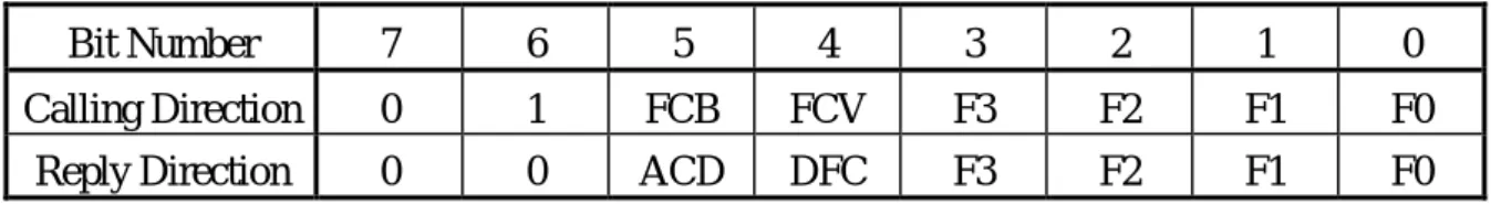
Besides labeling the functions and the actions caused by them, the function field specifies the direction of data flow, and is responsible for various additional tasks in both the calling and replying directions. Figure 14 shows the coding of the individual bits of the C field:
Bit Number 7 6 5 4 3 2 1 0
Calling Direction 0 1 FCB FCV F3 F2 F1 F0
Reply Direction 0 0 ACD DFC F3 F2 F1 F0
Fig. 14 Coding of the Control Field
The highest value (most significant) bit is reserved for future functions, and at present is allocated the value 0; bit number 6 is used to specify the direction of data flow. The frame count bit FCB indicates successful transmission procedures (i.e. those that have been replied to or acknowledged - see 5.4), in order to avoid transmission loss or multiplication. If the expected reply is missing or reception is faulty, the master sends again the same telegram with an identical FCB, and the slave replies with the same telegram as previously. The master indicates with a 1 in the FCV bit (frame count bit valid), that the FCB is used. When the FCV contains a "0", the slave should ignore the FCB. For more about the FCB see chapter 5.5. In the replying direction, both these bits can undertake other tasks. The DFC (data flow control) serves to control the flow of data, in that the slave with a DFC=1 indicates that it can accept no further data. With an ACD bit (access demand) with a value of 1, the slave shows
that it wants to transmit Class 1 data. The master should then send it a command to request Class 1 data. Such Class 1 data is of higher priority, which (in contrast to Class 2 data) should be transmitted as soon as possible. The support of Class 1 data and the bits DFC and ADC is not required by the standard.
The bits 0 to 3 of the control field code the true function or action of the message. Table 1 shows the function codes used in the calling and the replying directions. The functions shown in this table will be explained in more detail in the next section. All additional function codes defined in IEC 870-5-2 can also be used.
Name C Field
Binary
C Field Hex.
Telegram Description
SND_NKE 0100 0000 40 Short Frame Initialization of Slave
SND_UD 01F1 0011 53/73 Long/Control
Frame Send User Data to Slave REQ_UD2 01F1 1011 5B/7B Short Frame Request for Class 2 Data
REQ_UD1 01F1 1010 5A/7A Short Frame Request for Class1 Data
(see 8.1: Alarm Protocol) RSP_UD 00AD 1000 08/18/28/38 Long/Control
Frame
Data Transfer from Slave to Master after Request Table 1 Control Codes of the M-Bus Protocol (F : FCB-Bit, A : ACD-Bit, D : DFC-Bit)
A Field (Address Field)
The address field serves to address the recipient in the calling direction, and to identify the sender of information in the receiving direction. The size of this field is one Byte, and can therefore take values from 0 to 255. The addresses 1 to 250 can be allocated to the individual slaves, up to a maximum of 250. Unconfigured slaves are given the address 0 at manufacture, and as a rule are allocated one of these addresses when connected to the M-Bus. The addresses 254 (FEh) and 255 (FFh) are used to transmit information to all participants (Broadcast). With address 255 none of the slaves reply, and with address 254 all slaves reply with their own addresses. The latter case naturally results in collisions when two or more slaves are connected, and should only be used for test purposes. The address 253 (FDh) indicates that the adressing has been performed in the Network Layer (see chapter 7) instead of Data Link Layer. The remaining addresses 251 and 252 have been kept for future applications.
5.4 Communication Process 25
CI Field (control information field)
The control information field is already a part of the Application Layer, and is described in more detail in section 6.1. It was included in the telegram format used, in order to distinguish between the formats of the long and the control frames. The control information allows the implementation of a variety of actions in the master or the slaves.
Check Sum
The Check Sum serves to recognize transmission and synchronization faults, and is configured from specific parts of the telegram. These parts are mentioned when presenting the individual telegram formats in 5.2. The Check Sum is calculated from the arithmetical sum of the data mentioned above, without taking carry digits into account.
5.4 Communication Process
The Data Link Layer uses two kinds of transmission services:
• Send/Confirm : SND/CON
• Request/Respond : REQ/RSP
♣After the reception off a valid telegram the slave has to wait between 11 bit times and (330 bit times + 50ms) before answering (see also EN1434-3).
Send/Confirm Procedures
• SND_NKE →Single control character
This procedure serves to start up after the interruption or beginning of communication. The value of the frame count bit FCB is adjusted in master and slave, i.e. the first master telegram with FCV=1 after SND_NKE contains a FCB=1. The slave responds to a correctly received SND_NKE with an acknowledgment consisting of a single character (E5h).
• SND_UD →Single control character
With this procedure the master transfers user data to the slave. The slave can either confirm the correct receipt of data with a single character acknowledge ("$E5"), or by omitting a confirmation signal that it did not receive the telegram correctly.
Request/Respond Procedures
• REQ_UD2 →RSP_UD
The master requests data from the slave according to Class 2. The slave can either transfer its data with RSP_UD, or give no response indicating that the REQ_UD2 telegram has not been received correctly or that the address contained in the REQ_UD2 telegram does not match.
Minimum Communication
According to the European standard EN1434-3, as a minimum for communication the procedures REQ_UD2 / RSP_UD and ♣SND_NKE / $E5 are needed. All other functions are optional.
Transmission Procedures in case of faults
A fault in a received telegram can be detected by the receiver (master or slave), by checking the following points:
• Start /Parity /Stop bits per character
• Start /Check Sum /Stop characters per telegram format
• the second Start character, the parity of the two field lengths, and the number of additional characters received (= L Field + 6) with a long or control frame
When a fault has been detected as a result of the above checks, the transmission will not be accepted, and the reply or acknowledgement will not be sent.
After a time limit of (330 bit periods + 50 ms) the master interprets the lack of a reply as a fault and repeats the same telegram up to two times. If a valid telegram has not been received at that time a so called "idle time" of at least 33 bit periods is introduced. When slaves send faulty or corrupt replies, three attempts are also made, and if there is a fault during the last attempt then the 33 bit periods "idle time" is introduced.
5.5 FCB- and FCV-Bits and Addressing 27
5.5 FCB- and FCV-Bits and Addressing
(♣whole chapter reworked)
The FCB (Frame Count-Bit) in the REQ_UD2 can be considered as the LSB of a telegram counter of transmitted telegrams in the slave to master direction. On the other hand, the FCB in the SND_UD can be considered as the LSB of a (separate) telegram counter for the transmitted telegrams in the master to slave direction. A set FCV (Frame Count Valid)-Bit signals whether this frame count mechanism is active.
5.5.1 Applications of the FCB-mechanism
1.) Multi-telegram answers (RSP_UD) from slave to master
If a total answer sequence from a slave will not fit into a single RSP_UD (respond user data) telegram from the slave to the master, the master signals by a toggled FCB-Bit together with a set FCV-Bit in the next REQ_UD (Request user data) telegram that its link layer has properly received the last RSP_UD-telegram from the slave. The slave answers to a REQ_UD-request with toggled FCB-Bit with a set FCV-bit from the master with a RSP_UD containing the next link layer telegram section of a multi-telegram answer, otherwise it will repeat the last telegram. Note that a slave with a single RSP_UD-telegram may simply ignore the FCB in the REQ_UD2-telegram and send always the same (single) telegram. Note also that a slave with exactly two (sequential) RSP_UD-answer telegrams may simply use the FCB of the REQ_UD2 to decide which of both telegrams should be transmitted. Thus a slave with one or two (sequential) RSP_UD answer-telegrams does not require an internal "Last-REQ_UD2-FCB"-image bit. A slave with three or more (sequential) RSP_UD answer telegrams requires such an internal memory bit. Note that such an internal memory bit for the RSP_UD-direction must be independent of an possible additional internal memory bit for the SND_UD direction (see master to slave section).
2.) Frozen answer telegrams from slave to master
In same instances a slave will freeze the data of its last RSP_UD answer telegram into an additional temporary storage and will repeat these previously frozen RSP_UD answer, if the FCB has not been toggled. After the reception of a toggled FCB-Bit with a set FCV-Bit or after the reception of a REQ_UD2 with the FCV-Bit cleared, the slave will generate a next answer telegram reflecting the current state of all its data instead of repeating the data values frozen at the first REQ_UD2 attempt with toggled FCB. In meter applications this frozen-telegram aproach will result in possibly very old meter data if the last REQ_UD2 with toggled FCB-bit occured a long time ago. Thus for meter readout this frozen telegram technique is not recommended.
3.) Multi-telegram data (SND_UD) from master to slave
If the master sends a large (sequential) data block to a slave (e.g. RAM/EEPROM-initialize, code upload) which must be divided into multiple telegrams a similar situation like in the slave to master direction might occur. If the slave receives a telegram correctly and answers with a positive acknowledge (usually by a $E5 single byte answer) but the master does not receive this positive answer correctly, the master will repeat the last telegram with the identical FCB-Bit as in the first attempt. From this the slave can recognize that this next telegram does not contain the next data block but repeats the last data block which has been received correctly. So the slave may either ignore this telegram repetition completely or may accept it thus overwriting the last telegrams data with the second identical data. In both cases an internal telegram sequence counter is not incremented. Note that a slave which will accept only single telegram master to slave communication may simply ignore the FCB in the SND_UD. Note also that a master which can accept exactly two (sequential) SND_UD-telegrams may simply use the FCB of the SND_UD to decide which of both SND_UD-telegrams has been sent. Thus a slave which can accept one or two (sequential) SND_UD answer-telegrams does not require an internal "Last-SND_UD-FCB"-image bit. A slave which can accept three or more (sequential) SND_UD telegrams requires such an internal memory bit. Note that such an internal memory bit for the SND_UD-direction must be independent of an possible additional internal memory bit for the RSP_UD direction.
4.) Incremental actions in slave initiated by master
If single telegram SND_UD will initiate some incremental action in a slave (like toggling a relais or counting something) in contrast to sending some "absolute" data or parameters the FCB-mechanism allows as in the multi-telegram SND_UD situation a distinction between a repetition of the last telegram due to missed acklowledge reception and the next action. In this case the action is only taken if the FCB of the current SND_UD-telegram is different from the FCB in the previous SND_UD-telegram.
5.5.2 Implementation aspects for primary addressing
1.) Master
The master must always contain a "Next REQ_UD2-FCB-image bit" and also a "Next SND_UD-FCB image bit" for each primary slave address used by its application layer. After sending a SND_NKE-request to a slave adress both these "Next FCB-image bit" associated with this address contained in the request must be set. Thus for each primary address the first REQ_UD2 or SND_UD telegram after a SND_NKE contains a set FCB-Bit. Note that after a memory loss (usually due to a power failure) of these "Next FCB-image bits" the master is
5.5 FCB- and FCV-Bits and Addressing 29
required to send a SND_NKE to all affected addresses. All subsequent RSP_UD2-telegrams must contain the "Next REQ_UD2- FCB-image bit" of the appropriate primary address as a FCB. This "Next REQ_UD2 FCB-image bit" is toggeled after an error free link layer RSP_UD telegram has been received. All subsequent SND_UD-telegrams must contain the "Next SND_UD- FCB-image bit of the appropriate primary address as a FCB. If a SND_UD has been successfully transmitted to a slave (reception of a valid acknowledge byte $E5 or a valid RSP_ACK telegram) this "Next SND_UD-FCB-image bit" associated with this address is toggled.
2.) Slave
If a slave wants to utilize the FCB-Bit mechanism for the REQ_UD2-type (slave to master) transfers for more than two sequential telegrams it must provide a "Last REQ_UD2-FCB"-memory bit. If a valid REQ_UD2 telegram with a set FCV-Bit is received its FCB-Bit is compared to this "Last REQ_UD2-FCB-Bit". If they differ or the FCV-bit is clear, the next actual telegram data are used for the RSP_UD answer otherwise the last (stored) telegram is repeated.
If a slave wants to utilize the FCB-Bit mechanism for the SND_UD-type (master to slave) transfers for more than two sequential telegrams it must provide a "Last SND_UD-FCB"-memory bit. If a valid SND_UD telegram with a set FCV-Bit is received, its FCB-Bit is compared to this "Last SND_UD-FCB-memory Bit". If they differ or the FCV-bit is clear, the next actual telegram data are used for the RSP_UD answer otherwise the last (stored) telegram is repeated.
Note that after a valid reception of a SND_NKE to the primary address of the device or to the test adress 254 ($FE) or the broadcast adress 255 ($255) these internal "Last FCB" memory bits must be cleared.
3.) Implementation for multiple address slaves
A slave might be configured to respond to more than one primary address. This could be useful for slaves which internally consist of more than one independent functional blocks. If this slave wants to utilize FCB-funcionalities they must implement the appropriate number of internal memory bits (0, 1 or 2) for each of these adresses.
4.) Implementation for the primary (broadcast) address 255
All transfers to the primary broadcast address 255 ($FF) are not answered and should hence be implemented by the master with the FCV-Bit cleared. Note that a SND_NKE to primary address 255 will clear the internal "Last received FCB"-Bits of all slaves with primary addresses 0-250 and with FCB-Bit implementation simultaneously.
5.) Implementation for the primary (test) address 254 ($FE)
A slave should answer to all requests to the primary address 254 ($FE=test address) irrespective of its own primary address. The answer must contain its own primary address and not the address 254 ($FE). This test address is used by readout- or test equipment in point-to-point mode. Although this is a second primary address for each slave separate "Last received FCB"- Bit(s) are not required for this special case, since any test equipment or master is required to issue a SND_NKE after each reconnect or power fail thus clearing the "Last received FCB"-Bit(s) and thus preparing for a virgin transaction irrespective of the previous communication history.
6.) Implementation for secondary addressing
6.1 CI-Field 31
6 Application Layer
The standardized application protocol in the standard EN1434-3 for data exchange with heat meters will be the basis for the following discussion. This standard is also suitable for other consumer utility meters, e.g. for gas and water. However, EN1434-3 only covers the data structure in the reply direction, the data structure generally used in the direction master to slave will be presented here.
6.1 CI-Field
The CI-Field codes the type and sequence of application data to be transmitted in this frame. The EN1434-3 defines two possible data sequences in multibyte records. The bit two (counting begins with bit 0, value 4), which is called M bit or Mode bit, in the CI field gives an information about the used byte sequence in multibyte data structures. If the Mode bit is not set (Mode 1), the least significant byte of a multibyte record is transmitted first, otherwise (Mode 2) the most significant byte. The Usergroup recommends to use only the Mode 1 in future applications.
Mode 1 Mode 2 Application Definition in
51h 55h data send EN1434-3
52h 56h selection of slaves Usergroup July ´93
50h application reset Usergroup March ´94
54h synronize action suggestion
B8h set baudrate to 300 baud Usergroup July ´93
B9h set baudrate to 600 baud Usergroup July ´93
BAh set baudrate to 1200 baud Usergroup July ´93
BBh set baudrate to 2400 baud Usergroup July ´93
BCh set baudrate to 4800 baud Usergroup July ´93
BDh set baudrate to 9600 baud Usergroup July ´93
BEh set baudrate to 19200 baud suggestion
BFh set baudrate to 38400 baud suggestion
B1h request readout of complete RAM content Techem suggestion B2h send user data (not standardized RAM write) Techem suggestion
B3h initialize test calibration mode Usergroup July ´93
B4h EEPROM read Techem suggestion
B6h start software test Techem suggestion
90h to
97h codes used for hashing
obsolete and no longer recommended Table 2 CI-Field codes used by the master
Application reset (CI = $50)
With the CI-Code $50 the master can release a reset of the application layer in the slaves. Each slave himself decides which parameters to change e.g. which data output is default -after it has received such an application reset. This application reset by a SND_UD with CI=$50 is the counterpart to the reset of the data link layer by a SND_NKE.
Application reset subcode ♣
It is allowed to use optional parameters after CI = $50. The first parameter (the application reset subcode) defines which telegram function and which subtelegram is requested by the master. The datatype of this parameter is 8 bit binary. The upper 4 bits define the telegram type or telegram application and the lower 4 bits define the number of the subtelegram. The use of the value zero for the number of the subtelegram means that all telegrams are requested.
Slaves with only one type of telegram may ignore application reset and the added parameters but have to confirm it ($E5).
The following codes can be used for the upper 4 bits of the first parameter:
Coding Description Examples
0000b All
0001b User data consumption
0010b Simple billing actual and fixed date values+dates
0011b Enhanced billing historic values
0100b Multi tariff billing
0101b Instaneous values for regulation
0110b Load management values for management
0111b Reserved
1000b Installation and startup bus adress, fixed dates
1001b Testing high resolution values
1010b Calibration 1011b Manufacturing 1100b Development 1101b Selftest 1110b Reserved 1111b Reserved
6.1 CI-Field 33
Example:
The master releases an enhanced application reset to all slaves. All telegrams of the user data type are requested.
Master to Slave: 68 04 04 68 | 53 FE 50 | 10 | B1 16 Slave to Master: E5
Syncronize action (CI = $54) ♣
This CI-code can be used for syncronizing functions in slaves and masters (e.g. clock syncronization).
The use of the other control information codes is described in the chapters 6.4.1 (set baudrate to 300 .. 38400 Bd), 6.4.2 (data send) and 7 (selection of slaves).
The following codes can be used for the direction slave to master:
CI M=0 CI M=1 Application Defined in
70h report of general application errors Usergroup March ´94
71h report of alarm status Usergroup March ´94
72h 76h variable data respond EN1434-3
73h 77h fixed data respond EN1434-3
Table 4 CI-Field codes used by the slave
The use of these control information codes is described in the chapters 6.1 (fixed data respond), 6.2 (variable data respond), 6.6 (report of general application errors) and 8.1 (report of alarm status).
6.2 Fixed Data Structure
In the reply direction with a long frame two different data structures are used. The fixed data structure, besides a fixed length, is limited to the transmission of only two counter states of a predetermined length, which have binary or BCD coding. In contrast the variable data structure allows the transmission of more counter states in various codes and further useful information about the data. The number of bytes of the transmitted counter states is also variable with this data structure. Contrary to the fixed structure, the variable structure can also be used in calling direction. For this reasons the fixed data structure is not recommended for future developments.
To identify the fixed data structure, the numbers 73h/77h for the control information field are used. In this way the master software can see how it must interpret the data.
Identification No. Access No. Status Medium/Unit Counter 1 Counter 2
4 Byte 1 Byte 1 Byte 2 Byte 4 Byte 4 Byte
Fig. 15 Fixed Data Structure in Reply Direction (transmit sequence from left to right)
The Identification Number is a serial number allocated during manufacture, coded with 8 BCD packed digits (4 Byte), and which thus runs from 00000000 to 99999999.
The Access Numberhas unsigned binary coding, and is increased by one after each RSP_UD from the slave. With the field Status various information about the status of counters, and faults which have occurred, can be communicated - see Figure 16:
Bit Meaning with Bit set Significance with Bit not set 0 Counter 1 and 2 coded signed binary Counter 1 and 2 coded BCD 1 Counter 1 and 2 are stored at fixed date Counter 1 and 2 are actual values
2 Power low Not power low
3 Permanent error No permanent error
4 Temporary error No temporary error
5 Specific to manufacturer Specific to manufacturer
6 Specific to manufacturer Specific to manufacturer
7 Specific to manufacturer Specific to manufacturer
6.2 Fixed Data Structure 35
The field Medium/Unit is always transmitted with least significant byte first and gives the medium measured for both counter states, and the units for each of the two counter states. The units of counter 1 are coded with the first 6 bits of the first byte, and the units of counter 2 with the first 6 bits of the second byte. The coding of the medium is made up of the two highest bits of these bytes, and can therefore have 16 different values (4 bits). Tables to represent the physical units and the coding of the medium are in the appendix.
Byte Byte No. 8 (byte 2 of medium/unit) Byte No. 7 (byte 1 of medium/unit)
Bit 16 15 14 13 12 11 10 9 8 7 6 5 4 3 2 1
Medium physical unit of counter 2 Medium physical unit of counter 1
MSB MSB LSB LSB MSB LSB
Fig. 17 Coding of physical unit and medium in fixed data structure (data type E)
To allow transmission of one historic value with one of the two counters the special unit (111110b or hex code share of 3Eh) has been defined. This unit declares that this historic counter has the same unit as the other actual counter.
Example for a RSP_UD with fixed data structure (mode 1):
The slave with address 5 and identification number 12345678 responds with the following data (all values hex.):
68 13 13 68 header of RSP_UD telegram (L-Field = 13h = 19d)
08 05 73 C field = 08h (RSP_UD), address 5, CI field = 73h (fixed, LSByte first) 78 56 34 12 identification number = 12345678
0A transmission counter = 0Ah = 10d
00 status 00h: counters coded BCD, actual values, no errors
E9 7E Type&Unit: medium water, unit1 = 1l, unit2 = 1l (same, but historic) 01 00 00 00 counter 1 = 1l (actual value)
35 01 00 00 counter 2 = 135 l (historic value)
6.3 Variable Data Structure
The CI-Field codes 72h/76h are used to indicate the variable data structure in long frames (RSP_UD). Figure 18 shows the way this data is represented:
Fixed Data Header Variable Data Blocks (Records) MDH Mfg.specific data
12 Byte variable number 1 Byte variable number
Fig. 18 Variable Data Structure in Reply Direction
6.3.1 Fixed Data Header
The first twelve bytes of the user data consist of a block with a fixed length and structure (see fig. 19).
Ident. Nr. Manufr. Version Medium Access No. Status Signature
4 Byte 2 Byte 1 Byte 1 Byte 1 Byte 1 Byte 2 Byte
Fig. 19 Fixed Data Block
♣ In contrast to the fixed data structure here the Identification Number is a customer number, coded with 8 BCD packed digits (4 Byte), and which thus runs from 00000000 to 99999999. It can be preset at fabrication time with a unique number, but could be changeable afterwards, especially if in addition an unique and not changeable fabrication number (DIF = $0C, VIF = $78, see chapter 6.7.3) is provided.
The access numberis described above in the fixed data structure (see chapter 6.2).
The field manufacturer is coded unsigned binary with 2 bytes. This manufacturer ID is calculated from the ASCII code of EN 61107 manufacturer ID (three uppercase letters) with the following formula:
IEC 870 Man. ID = [ASCII(1st letter) - 64] • 32 • 32 + [ASCII(2nd letter) - 64] • 32 + [ASCII(3rd letter) - 64]
The field version specifies the generation or version of this counter and depends on the manufacturer. In contrast to the fixed data structure, the Medium is coded with a whole byte instead of four bits and the lowest two bits of the Statusfield are used to indicate application
6.3 Variable Data Structure 37
errors (see chapter 6.6). Apart from this, the significance of the individual bits of the Status field is the same as that of the fixed data structure. The Signatureremains reserved for future encryptation applications, and until then is allocated the value 00 00 h.
6.3.2 Variable Data Blocks
The data, together with information regarding coding, length and the type of data is transmitted in data records. As many blocks of data can be transferred as there is room for, within the maximum data length of 255 Bytes, and taking account of the C, A , and CI fields, the fixed data block. The upper limit for characters in the variable data blocks is thus 240 byte. The Usergroup recommends a maximum total telegram length of 255 bytes (234 bytes for variable data blocks) to avoid problems in modem communication. The manufacturer data header (MDH) is made up by the character 0Fh or 1Fh and indicates the beginning of the manufacturer specific part of the user data and should be omitted, if there is no manufacturer specific data.
Data Information Block
DIF DIFE VIF VIFE Data
1 Byte 0-10 (1 Byte each) 1 Byte 0-10 (1 Byte each) 0-N Byte Data Information Block DIB Value Information Block VIB
Data Record Header DRH
Fig. 20 Structure of a Data Record (transmitted from left to right)
Each data record contains one value with its description as shown in figure 20, a data record, which consists of a data record header (DRH) and the actual data. The DRH in turn consists of the DIB (data information block) to describe the length, type and coding of the data, and the VIB (value information block) to give the value of the unit and the multiplier.
The DIB contains at least one byte (DIF, data information field), and can be extended by a maximum of ten DIFE's (data information field extensions). The following information is contained in a DIF: Bit 7 6 5 4 3 2 1 0 Extension Bit LSB of storage number
Function Field Data Field :
Length and coding of data Fig. 21 Coding of the Data Information Field (DIF)

![Fig. 10 Block Diagram of the Transceiver TSS721 [4]](https://thumb-us.123doks.com/thumbv2/123dok_us/1784190.2754469/18.892.139.702.561.883/fig-block-diagram-transceiver-tss.webp)