Published: Proc. of DATE’01, S. 472-478, IEEE Press, 2001.
dlbSIM - A Parallel Functional Logic Simulator
Allowing Dynamic Load Balancing
Klaus Hering
Chemnitz University of Technology
Department of Computer Science
D-09107 Chemnitz
[email protected]
Jork L¨oser
Dresden University of Technology
Department of Computer Science
D-01062 Dresden
[email protected]
Jens Markwardt
Leipzig University
Department of Computer Science
Augustusplatz 10-11, D-04109 Leipzig
[email protected]
Abstract
To meet the demanding time-to-market requirements in VLSI/ULSI design, the acceleration of verification pro-cesses is inevitable. The parallelization of cycle-based sim-ulation at register-transfer- and gate level is one facet in a series of efforts targeted at this objective. We introduce dlbSIM, a parallel compiled code functional logic simulator that has been developed to run on loosely-coupled systems. It has the ability to balance the application-specific load of cooperating simulator instances in dependence of the over-all load situation on involved processor nodes. Thereby, the load of a simulator instance is expressed in terms of a set of circuit model parts which are to be simulated by the corresponding instance. The centralized load manage-ment runs simultaneously with a parallel simulation. Both processes interact after a controllable number of simulated clock-cycles to transmit load information and realize load modifications. dlbSIM is successfully used to simulate IBM S/390 processor models.
1. Introduction
Current deep-submicron design processes require a so-phisticated system of verification tools to ensure reliable design results under demanding time-to-market conditions. Design verification methods divide into two classes: formal verification [5] and simulation [7]. While the latter class represents the traditional way of design verification, formal methods have started to move from the research community
to the industrial domain only in the last years. There are strong indications that both classes will fruitfully comple-ment one another in the near future. Following [2], there is a promising potential for the development of methods that bring together aspects of both simulation and formal verifi-cation.
In this paper we focus on functional logic simulation of synchronous designs at gate- and register-transfer level. For system simulation processes it has proven to be a good practice to separate timing analysis from functional verifi-cation and leave corresponding tasks to dedicated tools as static timing verifiers and cycle-based simulators [1]. Sev-eral efforts have been made to accelerate cycle-based sim-ulation, including the use of BDDs to represent combina-tional logic [9], parallelization of compiled code simulation [3] and putting simulation activities into hardware resulting in hardware accelerators and emulators [4]. Among the al-ternatives mentioned, emulators by far realize the highest performance. Their use becomes more and more attractive because of the growing capacity of FPGA components. The high emulation speed comes at the expense of time con-suming model building processes and a loss in observable details during the emulation process. To cope with the lat-ter fact, a state dependent inlat-teraction of an emulator with a simulator would be useful. A parallel simulator version would allow fast evaluation during phases of tracking incor-rect behavior inside a circuit model. In general, simulation offers higher flexibility than emulation, both with respect to variations of the verification algorithm and the target hard-ware that is necessary for its realization. The successful usage of BDDs in cycle-based simulation of large circuits
depends on overcoming memory performance problems. A promising hybrid approach, replacing gate level representa-tions of some functional units with predefined macros, is to be found in [6]. This approach allows a combination of for-mal verification methods applied to certain functional units with traditional compiled code simulation techniques.
With dlbSIM, we introduce a parallel compiled code functional logic simulator dedicated to run on loosely-coupled systems and providing dynamic load balancing. It represents the successor of parallelTEXSIM [3]. To our knowledge, these simulators represent first approaches to parallel compiled code simulation. During the simulation of a circuit model with parallelTEXSIM, we have a fixed number of cooperating simulator instances, each instance handling exactly one part of the original model. Thereby, the assignment of model parts to simulator instances does not change. This is adequate to parallel simulations under exclusive use of a parallel machine or a workstation clus-ter. In practice, this condition is fulfilled only in individual cases. Since additional applications and system processes can seriously disturb the cooperation of simulator instances that are involved in a parallel simulation, we have devel-oped dlbSIM with an integrated load balancing mechanism that offers the possibility of adapting the simulation pro-cess to external influences. A similar approach for parallel event-driven simulation can be found in [8].
Within a dlbSIM simulation, we have a fixed number of cooperating simulator instances again, but each instance is handling a set of model parts. In general, a model part is assigned to several simulator instances. During simulation, at any point of time a subset of the model parts belonging to a simulator instance is active (under simulation). For each model part there is exactly one simulator instance where it is active (activity property). Then, load balancing appears as a modification of the sets of active model parts leaving the activity property unchanged.
The dlbSIM load management is running simultaneously with parallel simulation. The frequency of their interac-tion can be controlled via a parameter. An applicainterac-tion- application-based load balancing approach has the great advantage that application-specific knowledge can be included into deci-sions on load modifications [10]. In our case, a deci-sion to modify simulation-specific load is based on esti-mations of the time that would be necessary to simulate one cycle for the considered circuit model under the as-sumption the load modification had taken place. Besides external perturbances caused by other applications and sys-tem processes, the decision mechanism takes into consider-ation simulconsider-ation-specific imbalances and the possible het-erogeneity of the loosely-coupled processor system (a clus-ter of workstations, for instance) dlbSIM is running on.
In Section 2 we outline the parallelization approach that is underlying dlbSIM. The starting point is represented by
the sequential simulator MVLSIM (IBM). We provide the notion of a model partition and shortly characterize paral-lel simulation under dlbSIM including enhanced MVLSIM instances. In the next section, we continue with basic as-sumptions concerning load balancing. The combination of load management with parallel simulation is described in Section 4. In addition, the phases of load management are considered in more detail. Then, in Section 5 representative experimental results with respect to simulation of a large IBM S/390 processor model are given. The last section of this paper contains conclusions and addresses aspects of fu-ture work.
2. Parallelization approach
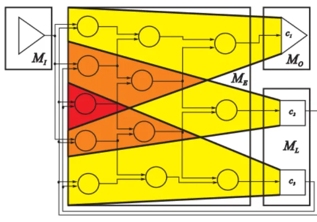
dlbSIM is based on the sequential functional logic simu-lator MVLSIM (IBM) for synchronous designs at gate- and register-transfer level. A corresponding structural circuit model M is depicted schematically in Figure 1. The basic model components are given by sets of global inputs MI,
global outputs MO, logic elements MEand storing
ele-ments ML. A set of nets representing wires that realize the
connection of circuit components is denoted by MS. There
are no feedbacks in combinational logic.
Figure 1. Structural circuit model with cone representations (shaded)
Within MVLSIM, cycle-based simulation is realized us-ing the levelized compiled code (LCC) technique. Logic el-ements are evaluated according to a rank ordering followed by the update of storing elements (for instance, latches) at cycle boundaries. The basic idea for the parallelization of the simulation process was to partition M in an adequate way and assign the resulting model parts to MVLSIM in-stances cooperating over a loosely-coupled processor sys-tem. We consider the set Co Mof all fan-in cones with
collection of basic building blocks for model partitioning. A corresponding cone comprises all logic elements out of
ME which have the capability to influence the cone head
during the simulation of one cycle. We derive a partition
π of M from a partitionπ¼
of Co Mthat represents a set
containing cone sets as elements. Each cone set C out of a partitionπ¼
directly allows the construction of a model part of M for inclusion intoπon the basis of the union of all el-ements belonging to cones out of C. Different model parts of a partition πare not necessarily disjoint, there may be an overlap between them. Furthermore, model parts of a partitionπgenerally have special input and output elements which represent communication ports for the signal transfer from and to other model parts ofπ. These ports are related to nets out of MS in the original model M which, at the
one hand, have a cone head belonging to a model part m0
as source and, at the other hand, feed a cone belonging to a model part m1m0. In practice, model partitioning for
dlb-SIM is realized using a BOTTOM-UP clustering technique for cones.
dlbSIM has been developed under the AIX Parallel En-vironment (PE) making use of its Message Passing Library (MPL). It is intended to run on IBM Scalable POWERpar-allel (SP) machines and on RS/6000 workstation clusters.
At run-time, dlbSIM appears in the form of a master component and a set SS1 Smof slave components.
All slave components run on different processor nodes. The master coordinates the work of the slaves, comprises a load management facility and provides an API. Slaves repre-sent MVLSIM simulator instances enhanced by a commu-nication shell and special facilities to handle circuit models within a parallel simulation. Each slave has the capability to manage a set of model parts. Let us assume to have a par-titionπM1 Mnof a circuit model M with nm
in preparation for a parallel simulation run. Then, first an initial distribution
D :π2
S (1)
of model parts (with 2S denoting the power set of S) has to be realized. Thereby, D Mispecifies the set of slaves
which have the possibility to simulate Miin a following
sim-ulation run. In practice, that means for a slave Sjto load all
model parts Miwith SjD Mibefore simulation. We
as-sume, that each simulator instance is included in the initial distribution, expressed by the condition Ë
n
i 1D MiS.
Furthermore, we require, that at any stage of a simulation run, for each Mj exactly one of its possibly multiple
oc-currences should be under simulation (active). We call this
activity property and represent the relation between model
parts and slaves that are currently simulating them by a function
A :πS. (2)
During a simulation of a sequence of clock-cycles for M, the slaves Sj execute a loop in parallel, the body of which
contains four steps in the order as given below. All slaves synchronize each other in the TRANSFER step.
CLOCK
Simulation of one clock-cycle for all model parts Mi
with A MiSj GET
Reading signal values from model-specific data struc-tures (nets) and writing them to output ports of model parts Miwith A MiSj
TRANSFER
Collective communication involving all slaves belong-ing to S to transfer signal values between model parts at cycle boundaries
PUT
Reading signal values from input ports of model parts
Mi with A Mi Sj and writing them to
model-specific data structures (nets)
3. Assumptions on load balancing
If we consider a parallel simulation run with dlbSIM, we distinguish two kinds of load: simulation-specific load and load caused by applications and/or system processes running in addition to dlbSIM on processors the simulator makes use of. Information with respect to the latter can be obtained in different forms from the operating system. We define simulation-specific load related to a slave Sj (at a
certain time during the parallel simulation) as the set of all model parts Miwith A MiSjaccording to 2. Thus the
simulation-specific load of a slave determines the amount of work (to be done by the corresponding slave) connected with the execution of the four basic steps for the simula-tion of one clock-cycle as mensimula-tioned above. The time to realize this work depends on load influences from outside the simulation and on the hardware configuration the slave is running on. Because of the synchronization of all slaves in the TRANSFER step, imbalances in the cycle simula-tion time between the slaves that are involved in the parallel simulation cause wait intervals. Our objective is to obtain a short overall simulation time for sequences of clock-cycles by balancing the cycle simulation times of the slaves. To achieve this, dlbSIM comes with a possibility to change simulation-specific load. Load modification appears as a modification of the current function A restricted by the ini-tial distribution D of model parts according to 1. This
way, a load modification does not involve a real move of model parts between slaves. If, for instance, it would be fa-vorable to reduce the cycle simulation time of slave 1 in Fig-ure 2 at the expense of the corresponding simulation time
of slave 2, the latter could take on the simulation of model parts 1 or 2. Including both slave 2 and slave 3, even the extreme case of completely discharging slave 1 would be possible. Load balancing under dlbSIM avoids process mi-gration and complete repartitioning of a circuit model under simulation.
Figure 2. Set of 3 slaves handling a model par-tition with 12 components, each component initially distributed to 2 slaves
4. Load management
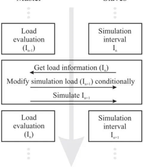
The dlbSIM load management is centralized in the mas-ter component. It comprises the request of load information, load evaluation and the modification of simulation-specific load (depending on the result of load evaluation). A se-quence of clock-cycles to be simulated for a given partition of a circuit model is divided into simulation intervals, the length of which (in terms of a number of cycles) can be controlled via a parameter. During a simulation interval In,
slaves work independent of the master that makes use of the time gap to evaluate load information stemming from
In 1(see Figure 3). After termination of a simulation
in-terval In the master receives load information from every
slave with respect to In. If the load evaluation concerning In 1has resulted in a decision to perform a modification of
simulation-specific load, the load information related to In
becomes invalid and the load modification is initiated (af-fecting In1). Otherwise, there is no load modification at
this point of time. Finally, the slaves are required to start
In1, and in case of valid load information related to In, this
information is evaluated by the master.
4.1. Load information
The determination of adequate load information is an es-sential basis for the estimation of both a load situation at hand and consequences of its modification. During a sim-ulation interval, each slave accumulates the time necessary
Figure 3. Load management and simulation for the evaluation of logic elements in the CLOCK step (per model part) and the time necessary for reading and writ-ing signal values to nets in the GET and PUT steps (per slave). Measured time values represent real run-time, in-cluding time intervals used by applications or system pro-cesses outside the simulation. Corresponding average val-ues are given to the master together with the ”load” value provided by the AIX operating system.
4.2. Evaluation of load information
The ”heart” of the load management is given by the re-cursive load balancing algorithm that is sketched in pseudo-code notation in Figure 4. Based on a current simulation-specific load of the slaves, the load information mentioned above and structural information with respect to the model parts, this algorithm investigates the effect of sequences of virtual model moves on the estimated simulation time for one clock-cycle of the corresponding model. Thereby, ”worst slave” means a slave that shows the highest amount of time for the simulation of one cycle at a current state of the execution of rec dlb. It is tried to come to better solu-tions (for the choice of active model parts on slaves) than a current best solution by moving models away from a current worst slave. For being deemed better than the best solution at the moment, it is not enough to show lower cycle simula-tion time, the time gain must be at least of a certain amount that is controlled by the parameter OFF and the current re-cursion depth. The parameter maxdepth limits the rere-cursion depth to guarantee termination of the algorithm and to con-tain the use of CPU and memory resources. It also restricts the set of investigated model part distributions. Because we allow one model move per recursion step, maxdepth
cor-relates to the maximum number of model moves per load modification. Obviously, it is possible that no better solu-tion than the start solusolu-tion is found. In this case, no load modification is suggested. The evaluation of load informa-tion results in a (possibly empty) list describing moves of model parts.
recursive procedure rec dlb (depth, maxdepth)
time := predicted cycletime s := worst slave
for all mπ: A ms do
for all rS : rs rD mdo
move model m to r
t := predicted cycletime
if t 1depthOFFtime then
time := t
save moves done up to now
fi
if depthmaxdepth then
call rec dlb (depth1, maxdepth)
fi
move model m to s
od od
Figure 4. Recursive load balancing algorithm, depth equals1at the first call
4.3. Load modification
For load modification, the list of moves resulting from the load balancing algorithm (if it is not empty) has to be transposed into new simulation-specific loads of slaves. To ”move” a model part from slave Sk to Sl it has to be
de-activated on Sk and activated on Sl where it has been
al-ready loaded since the beginning of the parallel simulation run. The model part’s state is extracted from Sk and
trans-ferred to Sl. There the state information is used to
initial-ize the local copy of the corresponding model part. Other slaves (if existent) are informed of that move. This way they can modify communication-related data structures before the start of the next simulation interval. The time needed to perform a model move mainly determines the OFF pa-rameter in Figure 4.
5. Experimental results
We present first results of experiments with dlbSIM con-ducted on a small heterogeneous cluster of workstations consisting of three RS/6000 workstations W1(2 GB RAM),
W2(1 GB RAM) and W3(64 MB RAM). These machines
are connected via a 10 MBit Ethernet network. In the fol-lowing, we summarize further conditions which all experi-ments under consideration had in common:
We have simulated 30000 clock-cycles of an IBM
S/390 processor model with about 27 million basic
el-ements, the hierarchy level being a mixture of gate-and register-transfer level. The model has been parti-tioned into 8 model parts M0 M7with sizes
rang-ing from 61 MB to 11 MB. The maximum recursion
depth of the load balancing algorithm was 3. (Previ-ous experiments with depth 5 did not show changes with respect to moves of model parts.)
There have always been three slaves S1S2 S3with Si
running on Wi. The master component ran on W1.
Fig-ure 5 shows the initial distribution of the model parts to the slave components.
During the experiments there was no load stemming
from other users. ”Disturbing processes” have been simulated in the experiments. In such cases, load has always been added on one node after 10000 cycles and removed after 20000 cycles.
Figure 5. Initial distribution of model parts Before considering experiments in more detail, we want to give some remarks related to the result representation. The charts in the Figures 6 and 8 show the total real run-time that was needed for each simulation interval (1000 or 500 cycles). This time includes both simulation time and time spent to realize possible model moves. Phases of moving models took about 1 to 2 seconds depending on the network traffic. The tables in Figure 7 show for each model part and given cycle intervals the slave where the model part is active.
Experiment ”No load”
During this experiment no load outside the simulation has been generated. Load balancing was enabled (the load balancing capability of dlbSIM can be switched off). The simulation interval comprised 1000 cycles. Results are shown in Figure 6 and Table (a) of Figure 7. The total run-time for the first 1000 cycles amounted to 460 s. Four phases of moving models (after 2000 4000 6000 and 8000 cycles) resulted in a total run-time of 210 s for one simu-lation interval. This time stayed stable until the end of the
simulation. The results show the ability of dlbSIM to com-pensate unfavorable choices of initial simulation-specific load on a heterogeneous system.
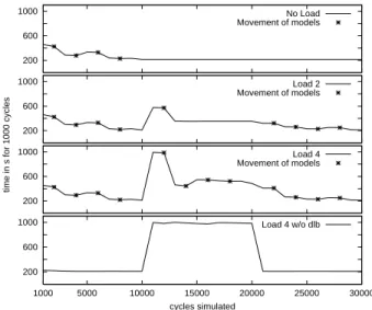
200 600 1000 1000 5000 10000 15000 20000 25000 30000 cycles simulated Load 4 w/o dlb 200 600 1000
time in s for 1000 cycles
Load 4 Movement of models 200 600 1000 Load 2 Movement of models 200 600 1000 No Load Movement of models
Figure 6. Total real run-time for simulation in-tervals of 1000 cycles
Experiment ”Load 4 without dlb”
This experiment started with the distribution of active model parts that was found in the previous experiment. Load balancing was disabled (see Table (c) of Figure 7). On W1, where S1was running, an additional load of 4 was
generated. The influence of the additional load is clearly to be seen in Figure 6.
Experiments ”Load 2” and ”Load 4”
In both cases, load balancing was enabled and the simu-lation interval comprised 1000 cycles. On W1, an additional
load of 2 and 4 was generated, respectively. Results are shown in Figure 6 and Table (b) of Figure 7. The repre-sentation of model moves is restricted to ”Load 2” because there are nearly the same results as with ”Load 4”. During the first 10000 cycles the run-times for corresponding sim-ulation intervals were the same as in the experiment ”No load”. Under load 2 4 these run-times increased from
210 s to 580 s 990s. Load information expressing the
changed load situation was available for the master com-ponent after 11000 cycles. In parallel to the next simulation interval, load evaluation resulted in a proposition of load modification. This modification took place after 12000 cy-cles, reducing the corresponding run-times to 350 s 490 s.
After removal of the additional load, several load modifica-tions were realized by dlbSIM. Finally, the same situation as immediately before generating additional load was reached
(both concerning the run-time of simulation intervals and the distribution of active model parts).
Figure 7. Slave components where model parts are active at given cycle intervals
0 50 100 150 200 250 300 500 5000 10000 15000 20000 25000 30000
time in s for 500 cycles
cycles simulated
Load 2 Movement of models
Figure 8. Total real run-time for simulation in-tervals of 500 cycles
Experiment ”Simulation interval 500”
This experiment represents a slight modification of ”Load 2” considered above. Different from the latter, the length of the simulation intervals is set to 500 cycles. As a consequence, there is a faster response to the generation of additional load and a faster improvement of the initial dis-tribution of active model parts. The corresponding results are shown in Figure 8. There is no difference to ”Load 2” concerning the distribution of active model parts both
im-mediately before load generation and at the end of the sim-ulation.
The above experiments focus on the ability of dlbSIM to adapt to additional load appearing on processor nodes involved in simulation. In case of exclusive sequential sim-ulation of the complete processor model on W1(W2/W3) the
average total run-time for 1000 cycles is 41 s (445 s/195 s). Experiments applying parallelTEXSIM to the simulation of the same processor model on an IBM SP2 parallel machine (under exclusive use) show the acceleration potential of par-allel compiled code simulation. In comparison to sequen-tial simulation, 4-way (12-way) parallel simulation runs re-sulted in average speed-up values of 298 (47).
6. Conclusions and future work
We have introduced dlbSIM, a parallel compiled code functional logic simulator that has been developed to run on loosely-coupled systems. It provides the possibility of dynamic load balancing with respect to simulation-specific load under consideration of the overall load situation of the processor system the simulator is running on. Experimen-tal results concerning the parallel simulation of real pro-cessor models have shown that the load balancing capabil-ity of dlbSIM can significantly reduce the simulation time under load influences stemming from outside the simula-tion. Furthermore, dlbSIM is able to compensate unfavor-able choices of initial simulation-specific load on a hetero-geneous system. It raises the attractiveness of using work-station clusters for long running simulation processes han-dling large circuit models.
There are many factors influencing the effect of dynamic load balancing with dlbSIM. In future work we will focus on the investigation of model partitioning and the initial dis-tribution of model parts to a set of slaves. Furthermore, vari-ations of the decision strategy realized in the load balancing algorithm will be subject of our work.
Acknowledgment
This work was supported by DEUTSCHEFORSCHUNGS
-GEMEINSCHAFT (DFG) under grant Sp487/1-3. The au-thors are grateful to W. ROESNER et al. (IBM Labora-tories Austin (TX)) and K.LAMB et al. (IBM Laborato-ries B¨oblingen) for valuable assistance. Special thanks to D.ZIKE for helpful discussions and to A.BLUHM for his contribution to the realization of experiments.
References
[1] S. Caplow. Cycle simulation: Technology, method-ology & mythmethod-ology. Electronic Product Design,
17(5):34–38, 1996.
[2] D. L. Dill. What’s between simulation and formal ver-ification? In Proc. of the 35th Design Automation
Conference (DAC’98), pages 328–329. ACM/IEEE,
1998.
[3] D. D¨ohler, K. Hering, and W. G. Spruth. Cycle-based simulation on loosely-coupled systems. In M. E. Schrader, R. Sridhar, T. Buechner, and P. P. K. Lee, editors, Proc. of the 11th Annual IEEE International
ASIC Conference (ASIC’98), pages 301–305, 1998.
[4] U. Kebschull, G. Koch, and W. Rosenstiel. The WEAVER prototyping environment for hard-ware/software co-design and co-debugging. In Proc.
of the Conference on Design, Automation & Test in Europe (DATE’98), pages 237–241, 1998.
[5] T. Kropf, editor. Formal Hardware Verification.
Springer Verlag, Berlin, 1997.
[6] Y. Luo, T. Wongsonegoro, and A. Aziz. Hybrid tech-niques for fast functional simulation. In Proc. of the
35th Design Automation Conference (DAC’98), pages
664–667. ACM/IEEE, 1998.
[7] K. Olukotun, M. Heinrich, and D. Ofelt. Digi-tal system simulation: Methodologies and examples. In Proc. of the 35th Design Automation Conference
(DAC’98), pages 658–663. ACM/IEEE, 1998.
[8] R. Schlagenhaft, M. Ruhwandl, C. Sporrer, and H. Bauer. Dynamic load balancing of a multi-cluster simulator on a network of workstations. In Proc. of the
9th Workshop on Parallel and Distributed Simulation (PADS’95), pages 175–180, 1995.
[9] C. Scholl, R. Drechsler, and B. Becker. Func-tional simulation using binary decision diagrams. In
Proc. of the IEEE/ACM International Conference on Computer-Aided Design (ICCAD’97), pages 8–12,
1997.
[10] J. Watts and S. Taylor. A practical approach to dy-namic load balancing. IEEE Transactions on Parallel