ISBN 0 7309 7808 7
May 1999
G
UIDELINES
ON
THE
S
AFE
D
ESIGN
AND
O
PERATING
S
TANDARDS
FOR
T
AILINGS
S
TORAGE
TABLE OF CONTENTS
Page
1. INTRODUCTION ... 1
2. TYPES OF TAILINGS STORAGE FACILITIES ... 2
2.1 Above ground storage ... 2
2.2 Below ground storage ... 3
3. HAZARD RATING OF TAILINGS STORAGE FACILITIES. ... 4
4. DERIVATION OF STORAGE CATEGORIES ... 4
5. DESIGN AND OPERATING STANDARDS ... 6
5.1 Categor y 3 facilities ... 6
5.2 Categor y 1 and 2 facilities ... 8
6. ADMINISTRATIVE PROCEDURES ... 9
7. SUGGESTED FURTHER READINGS ... 10
FIGURES
Figure 1 Hazard Rating/Height Matrix to derive TSF Categories ... 6TABLES
Table 1 Hazard Ratings -Mine Tailings Storage Facilities (after DME (QLD) (1995a)) ... 5Table 2 Design and Operating Requirements -Mine Tailings Storage Facilities ... 7
APPENDICES
Page
APPENDIX A Tailings storage data sheet ... 13 - 15
APPENDIX B Certificate of compliance - tailings storage facility
design ... 17 - 18
APPENDIX C Certificate of compliance - tailings storage facility
construction ... 19 - 20
APPENDIX D Design, construction and operational aspects to be
addressed for Category 3 tailings storage facilities ... 22 - 27
APPENDIX E Design, construction and operational aspects to
be addressed for Category 1 and Category 2 tailings
storage facilities ... 29 - 37
APPENDIX F Recommended aspects to be addressed in
construction documentation, periodic audits and
reviews, and pre-decommissioning reviews ... 39 - 42
APPENDIX G Recommended operational standards for tailings
storage facilities ... 43 - 47
APPENDIX H Recommended aspects to be addressed when
using in-pit methods of tailings storage facilities ... 49 - 52
APPENDIX I Additional information on the Department of
Environmental Protection requirements for tailings
1.
INTRODUCTION
The prime functions of a tailings storage facility (TSF) are the safe, long term storage of tailings with minimal environmental impact. Tailoring the design of a TSF to the site conditions, to ensure safety and minimise the environmental impacts, can lead to a reduction in total project costs.
These guidelines have been prepared by the Department of Minerals and Energy, Western Australia (DME) to assist in the design, construction, management and decommissioning of TSFs in Western Australia so as to achieve efficient, cost effective, safe and environmentally acceptable outcomes. The guidelines are intended to provide a common approach to the safe design, construction, operation and rehabilitation of TSFs, and to provide a systematic method of classifying their adequacy under normal and worst case operating conditions.
The approach adopted in these Guidelines recognises the desire of the mining industry to move towards self management by the use of a certificate of compliance for TSF design and a certificate of compliance for TSF construction.
The following Acts of Parliament currently govern safety and environmental issues of TSFs in Western Australia:
•
Mines Safety and Inspection Act•
Mining Act•
Environmental Protection Act:Part IV, Environmental Impact Assessment
Part V, Approval and Licenes for prescribed premises
•
The Rights in Water and Irrigation Act:Part III, Control of Waters
In some circumstances, TSFs may also be subject to additional legislation under the following:
•
Aboriginal Heritage Act•
Soil and Land Conser vation Act•
Conservation and Land Management Act•
Wildlife Conservation Act•
Land Administration Act•
Native Title Act•
Local Government ActAmong the aims of these guidelines is encouragement of the mining industry to take a longer term approach to the planning of TSFs. One of the factors critical to the final rehabilitation of a TSF is the management of the tailings deposition during the TSF operation. Without systematic tailings deposition and careful water management, the final rehabilitation could be very costly, and be required at a time when cash flow is limited or non-existent. Much of this challenge can be overcome by adequate planning, associated with good tailings management and the use of sound technical approaches early in the life of the facility.
It is recognised that not all of these guidelines may necessarily be applicable to all forms of tailings storage. A notable example is below ground storage of mineral sands tailings within mined out dredge ponds. In such circumstances the management of the operation should recognise and address the issues that are applicable to a particular tailings storage system.
2.
TYPES OF TAILINGS STORAGE FACILITIES
The prime functions of any TSF are two-fold, namely:•
safe and economical short-term storage of fine grained wastes to minimise thepossible environmental impacts; and
•
construction of an erosion resistant, non-polluting structure which is stable in thelong-term.
To achieve these functions, TSFs will need to be individually tailored to the site, the ore mineralogy, the process, and the desired long-term landform. As a result, TSFs would be expected to have a variety of designs and construction techniques. The design approach, construction method and decommissioning concept should be selected to suit the individual local conditions.
The total costs of investigation, site selection, design, construction, operation, monitoring and decommissioning should be considered for each possible design approach, and the most suitable and cost effective design should be selected. It is often the case that the l o w e s t i n i t i a l c a p i t a l c o s t d e s i g n m a y n o t b e t h e m o s t c o s t e f f e c t i v e w h e n decommissioning is also considered.
2.1
Above ground storage
In an above ground facility tailings are generally stored behind a purpose built embankment. The embankment may be constructed in several stages or in one pass to its designed maximum height. The purpose built tailings storage embankments differ significantly from conventional water storage dams in a number of important aspects, including:
•
The design life of a TSF is, effectively, perpetuity. A TSF could be considered tohave two phases in its life - a depositional phase with active human involvement followed by an erosion free, environmentally benign, stage with no further human inter vention, forever. A water storage dam on the other hand does have a finite design life, after which it may be removed and the site rehabilitated; alternatively it may be strengthened for further use. Throughout its working life a water storage dam will be monitored, and on-going maintenance and remedial work shall be carried out as long as water is stored behind the dam.
•
Rehabilitation aspects require careful consideration as TSFs cannot be breachedat the end of their service allowing the containment area or valley to return to its original condition. Instead, material and liquids or leachate must remain safely stored.
•
The materials stored behind the embankment may be loose or poorly consolidatedwith some contained water. Contaminants of varying toxicity may also be contained within the impounded material. Under severe seismic shock, saturated tailings may liquefy to produce a mobile fluid of high unit weight, which may lead to additional loading on the embankment.
•
The containing embankments are occasionally constructed by hydraulic deposition,rather than mechanised placement, of loose and saturated tailings materials and may themselves be subject to liquefaction and loss of strength under seismic loading.
•
Many TSFs are developed progressively as part of a mining operation; they may beconstructed in stages, over a period of years, with the embankment being raised to keep pace with tailings production. This in-built “performance and design review” allows for flexibility in approach when compared to conventional water
storage dams. However, this flexibility in design may be, to a certain degree, offset by a generally lower standard of construction control than is the case for water storage dams.
•
A well designed, constructed and operated TSF can achieve a significant drawdownof the phreatic surface in the tailings material near the embankment. As tailings deposition continues, with embankment raising, the embankment may derive a significant amount of structural support from the tailings material.
•
The storage of waste rock and tailings material in the same facility (co-storage)requires careful consideration of a number of factors including the available void volume in the rock material, the relative proportions of waste rock, tailings solids and tailings fluids, and the strength of the waste rock material and its resistance to compaction and consolidation with a consequent reduction in void volume.
•
The presence of sulphide materials in the TSF and their propensity to generateacid rock drainage will also need to be considered. The potential seepage of acidic leachate from the TSF needs to be recognised and managed in an environmentally appropriate manner.
In common with water storage dams, however, the control of seepage waters from TSFs is important for the maintenance of stability. Because of the arid climate in most of Western Australia, the water management aspects of TSFs are impor tant from an o p e r a t i o n a l v i e w p o i n t , i n a d d i t i o n t o t h e i r i m p a c t o n w a l l b u i l d i n g a n d f i n a l decommissioning.
2.2
Below ground storage
Direct storage in previously mined out open pits or underground openings is an alternative method for tailings storage used by some mine operators. In practice, this approach is more difficult to manage than above ground storage due to the difficulties with the removal of contained fluid, and the resultant low densities of deposited materials. Because of these challenges, approval to adopt below ground storage will usually require extensive geotechnical, hydrogeological and environmental studies to establish the viability and long-term safety of below ground storage of tailings.
Below ground storage should only be considered when:
•
there is no possibility of there being a potentially viable mineral resource beingsterilised by the deposition;
•
rehabilitation measures are provided to ensure that there is no long-termenvironmental impact or public safety hazard;
•
there is no possibility that the safety in the operating underground mines in thevicinity be jeopardised by the proposed TSF; and
•
future underground mining beneath the stored tailings is not contemplated or likely.The prime difficulty with in-pit storage is the rapid rate of rise of tailings level in the early phases of deposition where the pit is deepest and the exposed surface area is smallest, with a consequent reduction in the effect of solar drying and desiccation on a given volume of tailings, when compared with usual above ground TSFs of the same overall c a p a c i t y. Wa t e r m a n a g e m e n t i n t h e s e c i rc u m s t a n c e s c a n b e v e r y d i f f i c u l t , a n d consideration should be given to methods of increasing water recover y, or to water extraction and tailings slurry thickening before deposition.
3.
HAZARD RATING OF TAILINGS STORAGE FACILITIES
These guidelines have been prepared using a hazard rating system in accordance with other nationally and internationally accepted standards on TSF safety and rehabilitation. Individual TSFs are classified using a hazard rating that recognises the potential impact on the environment and any life, property, or mine infrastructure as a result of possible uncontrolled leakage or failure of the embankment.By using a hazard rating system, these guidelines clearly recognise that differences in design philosophy, the degree of technical input, and the type and nature of construction are appropriate for mine TSFs constructed in the various regions of Western Australia. The hazard rating is derived by considering:
•
the potential impact in terms of safety on any nearby community infrastructureand/or mining developments (including the TSF operator) in the event of either controlled or uncontrolled escape of material, seepage and/or abrupt failure of the TSF embankment at any stage in its life; and
•
the potential environmental impact in the event of either controlled or uncontrolledescape of material, seepage and/or abrupt failure of the storage embankment at any stage in its life;
•
the potential impact in terms of economics on any nearby community infrastructureand/or mining developments (including the TSF operator) in the event of either controlled or uncontrolled escape of material, seepage and/or abrupt failure of the TSF embankment at any stage in its life; such economic impacts should also consider the impact on the mining operation due to the temporary loss of the TSF resulting from the failure or uncontrolled escape of tailings from the facility. The hazard ratings to be applied to TSFs in Western Australia are shown in Table 1. The hazard rating given to an individual TSF is not an assessment of the risk of failure, but rather the potential impact in the event of controlled or uncontrolled escape of material or seepage, or the partial or complete failure of the embankment. Therefore, a well engineered and constructed embankment, or a well operated TSF, may still receive a High or Significant hazard rating. TSFs should be classified by considering the impact of both embankment failure and controlled, or uncontrolled, escape of material, or seepage.
The least favourable classification using this approach becomes the designated hazard rating for the TSF under consideration.
4.
DERIVATION OF STORAGE CATEGORIES
The hazard rating system is used, together with the size of the facility, to define three categories of TSF for which varying levels of detailed study and justification of design, operating procedures and rehabilitation measures are required. Rigorous and technically based justification is required for:
•
TSF embankments which are any artificial barrier or levee, whether temporar y orpermanent, which do or could impound, divert or control water, silt, debris or liquid borne materials, together with its associated works, with an anticipated maximum embankment height of 15 m or more; or
•
TSFs of any height which can be classified as posing Significant or High hazardsusing the rating system given in Table 1.
HAZARD RA
TINGS - MINE T
AILINGS STORAGE F
ACILITIES (After DME-QLD, 1995a).
HAZARD RATING High Significant Low olled r eleases
Location such that contamination
Location less critical but contamination
N
o
contamination of a water
of a water supply likely to be used
of a water supply likely to be used for
supply likely to be used for
for human consumption and
human consumption and consumption
human consumption expected.
consumption of the contaminated
of the contaminated water is possible
water is expected.
but not expected.
Location such that contamination
Location less critical but contamination
N
o
contamination of a water
of a water supply likely to be used
of a water supply likely to be used for
supply likely to be used for
for stock consumption and
stock consumption and consumption
stock consumption expected.
consumption of the contaminated
of the contaminated water is possible
water is expected.
but not expected.
onmental damage
Location such that damage to an
The significance of the envir
onmental No envir onmental featur es of envir onmental featur e of significant featur
e is less or damage is possible
significance or no damage
value is expected.
but not expected.
expected.
e
Loss of life expected because of
No loss of life expected, but the
No loss of life expected.
community or other significant
possibility r
ecognised. No urban
developments.
development and no mor
e than a
small number of habitable str
uctur
es
down str
eam.
Sever
e economic loss such as
Appr
eciable economic loss, such as
No significant economic loss,
serious damage to communities,
damage to secondar
y r
oads, minor
but possible limited damage to
industrial, commer
cial or
railways, r
elatively impor
tant public
agricultural land, minor r
oads,
agricultural facilities, important
utilities, mine infrastructur
e, the
mine infrastructur
e, etc.
utilities, mine infrastructur
e, the
storage itself or other storages
storage itself or other storages
downstr
eam.
downstr
eam.
ect Economic Loss
Storage essential for ser
vices and
Repairs to storage practicable.
Repairs to storage practicable.
repairs not practicable.
Indir
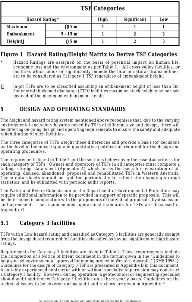
TSF Categories
Hazard Rating* High Significant Low
Maximum >15 m 1 1 1
Embankment 5 - 15 m 1 2 2
Height✝ < 5 m 1 2 3
Figure 1 Hazard Rating/Height Matrix to Derive TSF Categories
* Hazard Ratings are assigned on the basis of potential impact on human life,
economic loss and the environment as per Table 1. All cross-valley facilities, or facilities which block or significantly impede the flow in natural drainage lines, are to be considered as Category 1 TSF regardless of embankment height.
✝ In-pit TSFs are to be classified assuming an embankment height of less than 5m.
For central thickened discharge (CTD) facilities maximum stack height may be used instead of the maximum embankment height.
5
DESIGN AND OPERATING STANDARDS
The height and hazard rating system mentioned above recognises that, due to the varying environmental and safety hazards posed by TSFs of different size and design, there will be differing on-going design and operating requirements to ensure the safety and adequate rehabilitation of such facilities.
The three categories of TSFs weight these differences and provide a basis for decisions on the level of technical input and quantitative justification required for the design and operating procedures.
The requirements listed in Table 2 and the sections below cover the essential criteria for each category of TSFs. Owners and operators of TSFs in all categories must complete a tailings storage data sheet (Appendix A) which forms the basis for registration of all operating, disused, abandoned, proposed and rehabilitated TSFs in Western Australia. These data sheets should be updated periodically to reflect the changing storage statistics, and be submitted with periodic audit reports.
The Water and Rivers Commission or the Department of Environmental Protection may require additional information to be provided in support of specific proposals. This will be determined in conjunction with the proponents of individual proposals, by discussion and agreement. The recommended operational standards for TSFs are discussed in Appendix G.
5.1
Categor y 3 facilities
TSFs with a Low hazard rating and classified as Category 3 facilities are generally exempt from the design detail required for facilities classified as having significant or high hazard ratings.
Requirements for Category 3 facilities are given in Table 2. These requirements include the completion of a Notice of Intent document in the format given in the “Guidelines to help you get environmental approval for mining project in Western Australia” (DME 1998a). Guidelines for the design of Category 3 TSF are presented in Appendix D in this document. A suitably experienced contractor with or without specialist supervision may construct a Category 3 facility. However, during operation, a geotechnical or engineering specialist should audit and review Category 3 facilities on a three-yearly basis. Guidelines on the technical issues to be covered during audit and reviews are given in Appendix F
TABLE 2
DESIGN AND OPERATING REQUIREMENTS
MINE TAILINGS STORAGE FACILITIES
CATEGORY 1 CATEGORY 2 CATEGORY 3
Completion of Yes Yes Yes
Tailings Storage Data Sheet
Design Report prepared Report prepared Notice of Intent
in detail by geo- by geotechnical prepared as
technical or or engineering outlined in
engineering specialist specialist as in Appendix D.
as outlined in Appendix E.
Appendix E.
Construction Super vised by Brief construction Constructed by
geotechnical or report as in a suitably
engineering specialist. Appendix F with experienced
Detailed construction as-built drawings. contractor.
report as outlined in Appendix F with as-built drawings.
During Operations Annual inspection Inspection and audit Inspection and audit
and audit by Geo- every 2 years by every 3 years by
technical or Geotechnical or Geotechnical or
Engineering specialist Engineering specialist Engineering specialist
as outlined in as outlined in as outlined in
Appendix F. Appendix F. Appendix F.
Operation as per Operation as per Operation as per
Appendix G Appendix G Appendix G
Rehabilitation Inspection and Inspection and Inspection and
Phase decommissioning decommissioning decommissioning
report by Geo- report by Geo- report by
Geo-echnical or technical or technical or
Engineering specialist Engineering specialist Engineering specialist
as outlined in as outlined in as outlined in
Appendix F. Appendix F. Appendix F.
Provision of Yes Yes Yes
Emergency Action Plan
Routine daily Yes Yes Yes
5.2
Categor y 1 and 2 facilities
The design and operating requirements for Category 1 and 2 (as defined by the height/ hazard rating matrix Figure 1) TSFs are similar, and the specific differences in supporting documentation, design approach, construction control, and operating procedures are differences in the level of detail.
For Category 1 TSFs, considerably more detail is required. Both Categories 1 and 2 require design documentation and construction input from suitably qualified and experienced geotechnical and engineering specialists. Guidelines on the technical aspects to be covered at the design stage are given in Appendix E. Prescriptive requirements for these documents are not provided
It is the responsibility of the geotechnical and/or engineering specialist involved in the design of Category 1 and 2 facilities to determine the level of geotechnical and other professional input appropriate to the specified rating of the site. This should include consideration of the most severe and unfavourable combination of static and dynamic loads, where appropriate.
Where a change in the mining operations occurs, eg the development of an underground mine adjacent to a previously mined open pit and existing TSF, which may affect the hazard rating of the facility, then the hazard rating of the structure must be reassessed to take account of the change.
Construction of Categor y 1 and 2 facilities should be performed under the supervision of a suitably qualified geotechnical or engineering specialist. The specialist should produce an as-constructed report to confirm that the construction met the design intent. During operation, a geotechnical or engineering specialist should audit and review Category 1 and 2 facilities on a yearly and two-yearly basis respectively. Guidelines on the technical issues to be covered during construction, and during audit and review are given in Appendix F.
6
ADMINISTRATIVE PROCEDURES
For all mining projects in Western Australia a Notice of Intent (NOI) document addressing the environmental issues should be submitted as per Section 5 of the “Guidelines to Help You Get Environmental Approval for Mining Projects in Western Australia” (DME, 1998a). Figures 1, 2 and 3 of that guideline (DME, 1998a) show the NOI assessment and approval process administered by DME and the Department of Environmental Protection (DEP). The DEP’s role with respect to the assessment and approvals of TSFs is summarised in Appendix I.
As part of the NOI, a TSF design report should be produced in accordance with the guidelines given in this document. The design should be based on the hazard rating and TSF category as outlined in Sections 3 and 4 of this document. A completed tailings storage data sheet (Appendix A) should be included in the design report. Construction and operation of a TSF should be based on the guidelines given in this document.
The inclusion of a duly signed Certificate of Compliance for TSF Design, as specified in Appendix B, may expedite the DME assessment. Following the construction of the TSF or any additions thereto, a signed certificate of compliance for TSF construction, as specified in Appendix C, should be forward to DME.
The principal employer or manager of a mine must notify the District Inspector of the region, in which the mine is situated, of the commencement or suspension of mining operations (Section 42(1) Mines Safety and Inspection Act). The operation of a Prescribed Premises without a Licence may be an offence under the Environmental Protection Act, 1986.
For further assistance on geotechnical or environmental matters relevant to TSFs please contact Mining Operations Division, Department of Minerals and Energy, 100 Plain Street, East Perth WA 6004.
Telephone: Geotechnical (08) 9222 3401
Environmental (08) 9222 3437
Facsimile: Geotechnical (08) 9222 3441
7
SUGGESTED FURTHER READING
ANCOLD (1983). Guidelines for dam instrumentation and monitoring systems. Australian National Committee on Large Dams (ANCOLD), 88 pp.
ANCOLD (1986). Guidelines on design floods for dams. Australian National Committee on Large Dams (ANCOLD), 42 pp.
ANCOLD (1998). Guidelines on tailings dam design, construction and operation (Draft). Australian National Committee on Large Dams (ANCOLD), 59 pp.
ANZMEC (1995). Security Deposit Systems for Minesite Rehabilitation. Australian and New Zealand Minerals and Energy Council (ANZMEC), Report No 95.01, 7pp. ARR (1987). Australian Rainfall and Runoff, A Guide to Flood Estimation, 2 volumes,
third edition, 347 pp. 97 maps (The Institution of Engineers, Australia: Canberra). AS 1726-1993. Australian Standard, Geotechnical site investigations, 40 pp. (Standards
Association of Australia: Homebush).
DME(QLD) (1995a). Site water management, in Technical guidelines for the environmental management of exploration and mining in Queensland, January (Department of Minerals and Energy: Brisbane).
DME(QLD) (1995b). Tailings management, in Technical guidelines for the environmental management of exploration and mining in Queensland, January (Department of Minerals and Energy: Brisbane).
DME 1995. Report on a sur vey of the effects of Cyclone Bobby on Western Australian mines. Dept of Minerals and Energy Western Australia and the Chamber of Mines and Energy Western Australia, 21pp.
DME 1998a. Guidelines to Help You Get Environmental Approval for Mining Projects in Western Australia (March 1998).
DME 1998b. Guidelines on the Development of an Operating Manual for Tailings Storage (October 1998).
DME 1998c. Guidelines for Preparation of Annual Environmental Reports on Mining and General Purposes Leases (March 1998).
EPA (1996). Best Practice Environmental Management in Mining - Environmental Auditing. Environment Protection Agency (EPA), 64pp.
Fell R, MacGregor P and Stapledon D (1992). Geotechnical Engineering of Embankment Dams. AA Balkema, Rotterdam, 675pp.
ICOLD (1982). Manual on tailings dams and dumps. International Commission on Large Dams (ICOLD), Bulletin No. 45, 237 pp.
ICOLD (1989). A Guide to Tailings Dam Safety. International Commission on Large Dams (ICOLD), Bulletin No. 74.
ICOLD (1995). A Guide to Tailings Dams - Transpor t and Placement. International Commission on Large Dams (ICOLD), Bulletin No. 101.
I C O L D ( 1 9 9 6 ) . Ta i l i n g s D a m s a n d E n v i ro n m e n t - R e v i e w a n d R e c o m m e n d a t i o n s . International Commission on Large Dams (ICOLD), Bulletin No. 103.
ICOLD (1996). Monitoring of Tailings Dams - Review and Recommendations. International Commission on Large Dams (ICOLD), Bulletin No. 104.
ICOLD (1996). A Guide to Tailings Dams and Impoundments. International Commission on Large Dams (ICOLD), Bulletin No. 106.
MERIWA (1998). Research into Saline Tailings Disposal and Decommissioning. Minerals and Energy Research Institute of Western Australia, Report No 189, 595pp., Vols 1 & 2.
Newson T A and Fahey M, 1998. Saline tailings disposal and decommissioning, Volume I Main Report. MERIWA Project No. M241, Australian Centre for Geomechanics, Western Australia.
ANCOLD and ICOLD publications are available from the Australian National Committee
on Large Dams: Assistant Secretary
Australian National Committee on Large Dams
Telephone: 02 9631 4717 Website: www.ancold.org.au
DME guidelines are available on the DME web site:
APPENDIX A
TAILINGS STORAGE DATA SHEET
Please complete a separate sheet for each tailings storage facility (TSF)
1. PROJECT DATA
1.1 PROJECT NAME: 1.2 Date: 1.3 TSF name: 1.4 Commodity:
1.5 Name of data pr ovider:* Phone:* 1.6 TSF centre co-ordinates (AMG)
m Nor th m East
1.7 Lease numbers: 2. TSF DATA
2.1 TSF Status: Proposed ❏ Active ❏ Disused ❏ Rehabilitated ❏ 2.2 Type of TSF:1 2.2.1 Number of cells:2
2.3 Hazard rating:3 2.4 TSF categor y:4
2.5 Catchment ar ea:5 ha 2.6 Nearest water course:
2.7 Date deposition star ted (mm/yy) 2.7.1 Date deposition completed (mm/yy) 2.8 Tailings discharge method:6 2.8.1 Water recover y method:7
2.9 Bottom of facility sealed or lined? Y / N 2.9.1 Type of seal or liner:8
2.10 Depth to original gr oundwater level m 2.10.1 Original groundwater TDS mg/l 2.11 Or e process:9 2.12 Material storage rate:10
2.13 Impoundment volume (pr esent) x106 m3 2.13.1 Expected maximum x106 m3
2.14 Mass of solids stor ed (present) x106 tonnes 2.14.1 Expected maximum x106 tonnes
3. ABOVE GROUND FACILITIES
3.1 Foundation soils 3.1.1 Foundation rocks 3.2 Star ter bund constr uction materials:11 3.2.1 Wall lifting by:
Upstream ❏ Downstream ❏ Centr e line ❏
3.3 Wall constr uction by: 3.3.1 Wall lifting material:12
mechanically ❏ hydraulically ❏
3.4 Present maximum wall height agl:13 m 3.4.1 Expected maximum m
3.5 Cr est length (present) m 3.5.1 Expected maximum m 3.6 Impoundment area (present) ha 3.6.1 Expected maximum ha 4 BELOW GROUND/IN-PIT FACILITIES
4.1 Initial pit depth (maximum) m 4.2 Ar ea of pit base ha 4.3 Thickness of tailings (present) m 4.3.1 Expected maximum m 4.4 Cur rent sur face area of tailings ha 4.4.1 Final sur face ar ea of tailings ha 5 PROPERTIES OF TAILINGS
5.1 TDS mg/L 5.2 pH 5.3 Solids content % 5.4 Deposited density t/m3
5.5 Potentially hazardous substances:14 5.6 WAD CN g/L 5.7 Total CN mg/L
5.8 Any other NPI listed substances in the TSF?15 Y / N
EXPLANATORY NOTES
FOR COMPLETING
TAILINGS STORAGE DATA SHEET
The following notes are provided to assist the proponent to complete the tailings storage data sheet.
1 Paddock (ring-dyke), cross-valley, side-hill, in-pit, depression, waste fill etc.
2 Number of cells operated using the same decant arrangement.
3 See Table 1 in the Guidelines.
4 See Figure 1 in the Guidelines.
5 Internal for paddock (ring-dyke) type, internal plus external catchment for other
facilities.
6 End of pipe, (fixed), end of pipe (movable) single spigot, multi-spigots, cyclone,
CTD (central thickened discharge) etc.
7 Gravity feed decant, pumped central decant, floating pump, wall/side mounted
pump etc.
8 Clay, synthetic etc.
9 See list below for ore process method.
10 Tonnes of solids per year.
11 Record only the main material(s) used for construction eg: clay, sand, silt, gravel,
laterite, fresh rock, weathered rock, tailings, clayey sand, clayey gravel, sandy clay, silty clay, gravelly clay, etc or any combination of these materials.
12 Any one or combination of the materials listed under item 11 above.
13 Maximum wall height above the ground level (not AHD or RL).
14 Arsenic, Asbestos, Caustic soda, Copper sulphide, Cyanide, Iron sulphide, Lead,
Mercury, Nickel sulphide, Sulphuric acid, Xanthates etc.
15 NPI - National polution inventory. Contact Dept of Environmental Protection for
information on NPI listed substances.
ORE PROCESS METHODS
The ore process methods may be recorded as follows:Acid leaching (Atmospheric), Flotation
Acid leaching (Pressure) Gravity separation
Alkali leaching (Atmospheric) Heap leaching
Alkali leaching (Pressure) Magnetic separation
Bayer process Ore sorters
Becher process Pyromet
BIOX SX/EW (Solvent extraction/Electro wining)
Crushing and screening Vat leaching
APPENDIX B
Cer tificate of Compliance
Tailings Storage Facility Design
CERTIFICATE OF COMPLIANCE
TAILINGS STORAGE FACILITY DESIGN
For and on behalf of ... I, ..., being a duly authorised officer of the above company and a current corporate member of
* (The Institution of Engineers, Australia)
(The Australasian Institute of Mining and Metallurgy), do hereby certify and confirm that
the ... Tailings Storage Facility at the ... mine site has been designed in accordance with the current edition of the Guidelines on the safe design and operating standards for tailings storages issued by the Department of Minerals a n d E n e rg y, We s t e r n A u s t r a l i a a n d t h e d e s i g n i s re f e r e n c e d as... dated...
Signature of above person: ...
Signature of witness: ...
Name of witness: ...
Date: ...
APPENDIX C
CERTIFICATE OF COMPLIANCE
CERTIFICATE OF COMPLIANCE
TAILINGS STORAGE FACILITY CONSTRUCTION
For and on behalf of ... I, ...(Registered Manager), do hereby certify and confirm that the
... Tailings Storage Facility at the ... mine site has b e e n c o n s t r u c t e d i n a c c o r d a n c e w i t h t h e d e s i g n p r e p a re d by... reference...dated... and the current edition of the Guidelines on the safe design and operating standards for tailings storages issued by the Department of Minerals and Energy, Western Australia.
For a category 1 tailings storage facility, an employee of the design organisation, being a
current corporate member of * (The Institution of Engineers, Australia)
(The Australasian Institute of Mining and Metallurgy)
shall certify that the above storage facility has been constructed, as far as reasonably practical, in accordance with the design referenced above.
Signature of design consultant: ...
In addition, the above facility will be operated in accordance with the design intent.
Signature: ...(Registered Manager)
Signature of witness: ...
Name of witness: ...
Date: ...
APPENDIX D
DESIGN, CONSTRUCTION AND OPERATIONAL ASPECTS
TO BE ADDRESSED FOR
DESIGN, CONSTRUCTION AND OPERATIONAL ASPECTS
TO BE ADDRESSED FOR
CATEGORY 3 TAILINGS STORAGE FACILITIES
Category 3 facilities are defined as shown on the height/hazard rating matrix (Figure 1). The Notice of Intent proposal documentation should provide the following information:
1.
SUMMARY
All proposals for TSF construction and operation in Western Australia submitted to DME should contain a detailed summar y of the proposal and list of commitments. This summary and list of commitments, which should not exceed seven pages in total, will then be available for public search at all DME offices.
It is important that the contents of the summary be given careful consideration to avoid the need for amendments to be recorded during the assessment phase.
Suggested contents for the summary are location, tenements, brief outline of the project and statements that the local Council and pastoralist have been contacted, and a document provided to Council. A map is not to be included in the summary.
A list of commitments to safeguard the environment is to be included. This list is to state the commitments, and not to refer to Sections within the body of the document. Confidential or proprietary information should not be included in the summary section. This information, where required, should be supplied separately so that it can be removed from the main document. Any such information should be clearly marked CONFIDENTIAL.
2.
INTRODUCTION
A brief summary of the proposal and, if appropriate, its relationship to any existing operation should be provided. The following information is required:
• Location, including tenement details, AMG Co-ordinates and a suitably scaled plan
• Ownership and Management Structure
• Brief Histor y - include history of approvals by other agencies if appropriate
• Existing Facilities - suitably scaled plans of lease and site as per Tailings Storage
Data Sheet
3.
GENERAL INFORMATION
• Process Type
• Rated throughput as dry tonnes/year
• Ore Type(s)
• Tailing Production Rate as dry tonnes/year
• Environmental performance to date (if existing operation)
4.
TAILING PROPERTIES
4.1 Mineralogy and/or composition
•
Base metal content (Cu, Pb, Zn, Ni, As, etc)•
Residual Gold•
Sulphide content, as percentage of elemental sulphate4.2 Residual process chemicals
•
Total Cyanide ex-plant in ppm•
Total Cyanide in tailings return water in ppm•
Free Cyanide ex-plant in ppm•
Free Cyanide in tailings return water in ppm•
other process chemicals added and show amounts and fates•
Salinity of process water in mg/l•
Salinity of tailings return water in mg/l•
pH of slurry ex-plant•
pH of tailings return water5.
TAILINGS STORAGE STRUCTURE
•
Plan and section: A detailed contour plan and section of the proposed storage should be provided.•
Constr uction method: A description of the site preparation and construction procedures including details of any supervision to be provided, test procedures, etc.•
Area: The total area of the structure and the functional area for tailings disposalat start-up, full production and at close of operations.
•
Height/depth: Ultimate design height of tailings storage facility and number of lifts envisaged.•
Capacity: The volume of storage available for tailings and expected dry tonnes capacity, i.e. allowance for non-recovered water content must be made.•
Wall angles: Final outer wall angle (DME recommendation is a maximum of 20ofrom horizontal for any outer slope, but this depends on materials to be exposed, and their erodibility).
•
Decant/underdrainage system: Provide details of design and expected performance of any decant or underdrainage (DME’s objectives are to achieve maximum tailings density and water recover y for process plant recycling). Designs without a decant or underdrainage must be justified, and have sufficient surface area to achieve acceptable tailings density by evaporation between placement cycles. Designs which incorporate upstream wall lifts using tailings may not be permitted unless some form of central decant is employed.•
Liners: Details of the liners (if used). Decant or return water sumps must be lined preferably using synthetic liners.6.
TAILINGS DENSITY
•
Average slurry density ex-plant ) Estimates for•
Estimated final tailings density ) new operations;•
Estimated angle of internal friction ) actual where•
Particle size distribution ) possible for•
Hydraulic conductivity and/or permeability) existing operations.7.
TAILINGS DISPOSAL SITE DETAILS
•
General description of the site topography (including a plan)•
Description of soils•
Brief description of vegetation•
Sub-soil conditions and superficial deposits (provide details of any geotechnicalinvestigations undertaken)
•
Geological description (particular attention to mineral potential, rock types andfracture systems)
•
Groundwater: data on depth, quantity and quality {analysis of pH, salinity, cyanide(free, WAD, total) and metals is required}
•
Water resources (details of any surface or groundwater use in the vicinity of theTSF: the Water and Rivers Commission should be contacted for details of known water resources)
•
Catchment area•
Runoff diversion. Details of any diversion structures needed to by-pass runoffincluding materials to be used and emplacement procedures. Indicate the design storm event.
8.
TAILINGS DEPOSITION METHOD
Details of deposition procedures and approximate rate of rise of the tailings surface. Deposition should be such that tailings are fully dried between each cycle. Designs using upstream construction with tailings materials for wall lifts will be required to technically justify any proposed use of open ended pipe discharge techniques in preference to multi-point discharge techniques.
9.
CLIMATIC CONDITIONS
The design must have a demonstrated ability to cope with both average and extreme-event climatic conditions. For design purposes in routine cases, a minimum 50-year return period should be used for rainfall/runoff events during operations. For the assessment of flood capacity after decommissioning, a more seasonal approach to rainfall should be adopted, with a 100-year return period wet season being used.
10.
MONITORING
The aims of monitoring are to provide a measure of actual performance against expected performance as described in the Notice of Intent for the project. In addition to conventional environmental monitoring for dust, gases and water, it is recommended that monitoring of such aspects as achieved tailings densities and properties, available storage volumes and deposition time remaining, should be performed on a regular basis to assist with management planning. The results of environmental trials for final rehabilitation, in addition to the performance of the facility during significant seasonal events, should also be considered as part of the facility monitoring to aid rehabilitation planning.
A description of all monitoring procedures is required. Details of the sampling locations, frequency and parameters should be provided. The detailed design for the TSF should address the measures to be taken to limit the extent and amount of contamination, and the monitoring program should provide the means to assess the effectiveness of the measures taken.
It is a DME requirement that all fauna deaths and any technical malfunction resulting in tailings or water escaping from the containment system be reported to the Regional Mining Engineer. All tailings pipe lines not equipped with automatic cut-outs in the event of pipe failure are to be buried, or located in a suitably bunded easement capable of containing any spill for a period equal to the time between routine inspections.
Decant or return water ponds are to be fitted with a warning system that will alert plant operators to any possible overflow.
11.
EMERGENCY ACTION PLAN
A detailed emergency action plan should be provided to include an assessment of the risk to life, property, and the environment downstream of the facility and details of any flood warning systems and emergency preparedness.
12.
DECOMMISSIONING/REHABILITATION PROPOSALS
DME requires decommissioned TSF to achieve three outcomes. They must be safe, stable, and aesthetically acceptable.
The following notes define, as near as practicable, DME’s understanding of what the words “safe, stable, and aesthetically acceptable” mean.
12.1 “Safe”
Decommissioned TSFs must be left in a manner, which does not allow them to breach any of the embankments necessary for containing the tailings. Decant systems, if used, will be fully decommissioned and made safe so that when normal weather forces act on the TSF the decant systems will not be a cause of undermining the embankment. The embankment walls should be left in such a condition that they would not be heavily eroded by surface run-off from the structure. In particular, considerable attention should be paid to the probability of gullies developing on the wall and any capping of the wall to armour it against erosion should be specifically designed to minimise gully development.
The outer walls or embankments should also be protected against the erosion effects of any surface run-off from around and upstream of the structure that could undercut the structure and cause it to collapse. Where across-valley structures have been built considerable attention must be paid to the interface between the natural topography and the TSF embankment to ensure this does not become a zone of excessive erosion. A TSF is considered to be safe when the retaining embankment will not be breached and where the contents of the TSF are not able to pollute the surrounding areas. The ground water or the surface water should not be adversely affected as a result of either liquor or metals leaching from the structure. In order to achieve this safe condition, it may be necessar y to have an extended decommissioning period to ensure any groundwater mound developed under the TSF is reduced significantly to largely eliminate any ongoing pollution.
12.2 “Stable”
All natural and human-made structures subject to weathering will be eroded to some degree. DME requires that the decommissioned TSF should not erode at an excessive rate. This generally requires that the outer batters of the TSF are constructed to shallow angles which will vary according to the material used in their construction. In addition, other erosion control methods such as limiting the length of the batter and constructing intercept and/or drop structures may be necessar y. All structures should be left with an effective drainage management system that takes into account the long-term erosion impacts of rainfall, the consolidation of the structure and wind erosion. It is anticipated that the surface of the TSF will have an erosion resistance similar to that of the surrounding areas.
Considerable care should be exercised when capping is used as it must be sufficiently well engineered to resist the development of gullies in peak rainfall events and avoid the long term problems that may be caused by the materials used in such capping breaking down during weathering.
12.3 “Aesthetics”
While DME recognises that aesthetics are a largely subjective matter, it also believes that the TSF should blend into the landscape and the visible portions of the structure should be covered by a suitable self-sustaining vegetation. In the rare event that this cannot be achieved other options will be considered by DME on a case by case basis.
12.4 Proposals
As each TSF is unique in terms of mineralogy, process, management, design, climate and location, it is expected that rehabilitation solutions may also be unique to each facility. It is acceptable for the proponent to provide alternative decommissioning systems, especially for the surface of the facility, to DME for consideration and approval. Proposals for rehabilitation of the TSF should include descriptions of the following:
•
the stage by stage plans to rehabilitate the TSF embankment and surface area;•
measures to control dust, water erosion, and contamination of surface andsub-surface waters;
•
proposals for decommissioning of any decant and under-drainage systems;•
Measures to provide long term wall stabilisation; DME recommendations are forlayer and suitable drainage control measures to ensure that there is minimum
potential for long term erosion; it is emphasised that slopes of 20o may not be
suitable for fine grained, or highly erodible materials, without adequate armouring; where such fine grained or erodible materials exist at the surface, slopes of less
than 20o may be required to minimise gully erosion.
•
Measures to provide long term surface stabilisation; DME recommendations are tocover the top surface of the TSF with a minimum of 500 mm of suitable waste where saline process water has been used, followed by spreading of topsoil and seeding; those facilities which use potable quality water during ore processing may not require the top surface to be covered with waste, but should be ripped, seeded, and fertilised to encourage revegetation to reduce the erosion and dusting hazards.
•
Measures to be taken to establish a self regenerating cover compatible with thesurroundings; to achieve this, topsoil or a growth medium could be spread on all external surfaces and, where necessary, additional seed and fertiliser applied.
•
Measures to be taken to minimise the possibility of uncontrolled release anderosion during flood periods, and endangerment to life; decant and underdrainage systems should be decommissioned, sumps refilled and a drainage control system developed to shed rainfall runoff from all external surfaces so as to minimise the possibility of erosion.
APPENDIX E
DESIGN, CONSTRUCTION AND OPERATIONAL
ASPECTS TO BE ADDRESSED FOR CATEGORY 1
AND CATEGORY 2 TAILINGS STORAGE FACILITIES
DESIGN AND OPERATIONAL ASPECTS TO BE ADDRESSED
FOR CATEGORY 1 AND 2 TAILINGS STORAGE FACILITIES
The proposals for Category 1 and 2 TSFs should provide the information given in Sections 1, 2, 3, 4 and 6 of Appendix D to this guideline. In addition, proposals should address the following:1.
SITE SELECTION
A site for a TSF should be selected with due consideration of the impact of the facility on the surrounding infrastructure and environment, particularly in the event of an abrupt embankment failure, either during operations or after abandonment. Among the factors that should be considered in the selection of a TSF site are:
•
the water tightness of the foundation material;•
the influence of the watershed draining into the TSF area - preferably this shouldbe kept to a minimum;
•
the proximity to major streams or creek systems and the potential impact offlooding; and
•
the proximity to mine infrastructure, centres of population, operational mine sites(especially underground operations), or areas of environmental significance. A discussion should be presented on the considerations given to site selection.
2.
HYDROLOGICAL AND HYDRAULIC ANALYSES
2.1 Design Floods
The design of Category 1 and 2 facilities must take account of the impact of storm flooding in terms of external toe erosion as well as internal flooding throughout their operating life. Rainfall in Western Australia can at times be extremely heavy, and this must be taken into account at all stages of the TSF development.
To obtain data for design flood estimation ARR (1987), Australian Rainfall and Runoff , is recommended as a reference. In general, there is little hydrological data in the remote mining areas of Western Australia that can be used as a basis for the estimation of probable maximum flood levels. In these situations, correlation with records from nearby areas with similar characteristics may be adopted. Care must be exercised, however, with this approach and resulting estimates must be checked during operations by specific field measurements of runoff, previous flood marks, etc.
If natural drainage diversion becomes necessary for the construction of a TSF, all safety issues arising from water diversion measures must be suitably addressed at the design stage. Special attention must be given to minimise the potential for flooding operating mines, residential areas and access roads due to a combined effect of extreme rainfall events and natural drainage diversion measures associated with the TSF. This is a legal requirement as per Regulation 4.11 of the Mines Safety and Inspection Regulations, 1995 (MSIR).
Due to the arid climatic conditions and relatively flat topography in major mining areas of Western Australia, the potential for flood hazards may not be apparent unless a detailed
hydrological study is conducted for the area. Attention is drawn to DME (1995), Report on a Survey of the Effects of Cyclone Bobby on Western Australian Mines, for recorded information on damage resulting from extreme rainfall events in the mining areas of Western Australia.
In the post-decommissioning phase, the requirement for passing flood discharges should be considered. In this situation, the approach to floods will need to be more of an examination of seasonal conditions, when ring-dyke (paddock) type facilities are being assessed. Individual storm events may not cause problems in terms of storage capacity, but the possibility of successive events in wet seasons when evaporation rates are low, will need to be considered.
2.2 Freeboard
The design of a TSF should be such that the embankment, irrespective of the method of construction, should maintain sufficient freeboard to store the maximum predicted event that may occur during the life of the facility, using a worst case situation assuming no decant, such as will occur after decommissioning.
The purpose of freeboard is to provide a safety margin over and above all the estimated inflows of fluids from extreme natural events and operational situations, so that the risk of overtopping leading to embankment erosion and ultimate failure of an above ground TSF is minimised. The maintenance of an adequate freeboard on a TSF is important, particularly when the deposited tailings and/or fluid level reaches the embankment crest level. The freeboard should be sufficient to contain unforeseen increases in the level and movement of fluid within the facility caused by the following:
•
Tailings spills or overflow from spigot malfunctioning;•
Back flow and overtopping as a result of mounding of tailings at discharge points;•
Outlet and/or recovery system failures;•
Uncertainties in design rainfall estimates;•
Uncertainties in design catchment and runoff estimates;•
Extreme wind effects such as wave runup and wind setup;•
Any other effects, such as seismicity, land slips etc. that may generate waves.It is recommended that the freeboard should be specified according to the following, and as shown on Figure 1.
Case 1: For a TSF with a water pond normally located away from any perimeter embankment:
Total Freeboard = Operational Freeboard + Beach Freeboard = 500mm with a sub-minimum of 300mm Operational Freeboard.
Case 2: For a TSF with a water pond normally located against a perimeter embankment but with no upstream catchment apart from the storage itself: Total Freeboard = Operational Freeboard = 500mm.
Total Freeboard is defined as the vertical height between the lowest point on the crest of the perimeter embankment of the TSF and the normal operating pond level plus an allowance for an inflow corresponding to the 1:100 year 72-hour duration rainfall event falling in the catchment of the pond, assuming that no uncontrolled discharge takes place for the duration of the rainfall event. (Note: the Total Freeboard also corresponds to the sum of the “Operational Freeboard” and the “Beach Freeboard” as defined below.)
Operational Freeboard is defined as the vertical height between the lowest elevation of the perimeter embankment and the tailings beach immediately inside the embankment. The operational freeboard varies over the course of a deposition cycle as the storage is raised and fills with tailings. The operational freeboard becomes critically important at the end of a deposition cycle, particularly to minimise the potential for back flow and overtopping as a result of mounding of tailings at discharge points.
FIGURE 1: Definition of Freeboard
Beach Freeboard is defined as the vertical height between the normal operating pond level plus an allowance for an inflow corresponding to the 1:100 year 72-hour duration rainfall event falling in the catchment of the pond, assuming that no uncontrolled discharge takes place for the duration of the rainfall event, and the point on the beach where the wall freeboard is measured. The Beach Freeboard can vary significantly during the life of the storage and depends upon beach length, slurry/tailings characteristics, deposition methodology etc. Beach Freeboard is not applicable where the pond is normally located against a perimeter embankment.
Where relevant, the following information should be provided within the proposal:
•
a topographic map of the catchment and description of the terrain includingelevations;
•
the area of the catchment and of each sub-area controlled by other TSFs or lakes;•
summaries of streamflow, flood flow or rainfall records on which the hydrologicalanalyses are based;
•
tables or curves of reservoir area and storage capacity versus water surface level;•
summaries, as applicable, of hydrological analyses leading to the determinationof flood frequencies, probable maximum flood, reservoir capacity, outlet capacity, and freeboard above maximum flood level and capacity of flood diversion measures;
•
estimated rates of production of tailings or industrial wastes to be stored;•
particulars of any proposal for reclaiming water from storage; capacity of returnwater pond(s) and automatic shut-off valves/mechanisms for decant outfall pipe and underdrainage collection pipes;
•
particulars of any proposal for pumping or otherwise discharging excess water;•
assumptions as to loss of water by evaporation. Attention is drawn to the MERIWAProject No. M241, Saline tailings disposal and decommissioning (Newson T A and Fahey M, 1998) for estimating evaporation rates; and
•
the minimum freeboard to be maintained at relevant stages of the tailingsdeposition cycle to minimise the potential for tailings spills (see section 2.2);.
4.
GEOTECHNICAL INVESTIGATIONS
The scope and extent of the geotechnical investigations required to justify the design of a TSF will vary depending on the following:
•
the hazard rating and size of the proposed facility; and•
the complexity of local geotechnical conditions.Attention is drawn to Australian Standard AS 1726-1993, Geotechnical site investigations, as a basis for determining the level of detail and/or the extent of the geotechnical site investigations.
The scope of the geotechnical investigation should be designed to cover the following aspects:
•
the site geology of both the superficial and bedrock formations, including detailsof the soil and bedrock stratigraphy, giving information on the depth, thickness, continuity and composition of each significant layer as well as information on the history of deposition, erosion, and any diagenetic processes that may have altered the soil and rock materials;
•
the hydrogeological properties of the site, including the determination of thepotential aquifers and aquicludes, identification of the local and regional piezometric surfaces, and if necessar y, the piezometric pressures within each aquifer, determination of hydraulic conductivity or permeability and the local and regional groundwater flow systems; groundwater chemistry (pH, TDS, CN and other substances as required by DEP);
•
engineering proper ties of the foundation materials; a sufficient number of•
the nature and extent of any proposed foundation treatment including provisions for drainage;•
the availability of natural or already existing materials suitable for use inembankment construction, and/or use in the treatment of the foundation area of the facility; the results of any laboratory testing should be included;
•
the geotechnical properties of the construction material (soil, rock, and, ifavailable, tailings material) and consideration of the manner in which these properties may have an impact on the design and operation of the structure;
•
the requirement for specific measures to limit seepage either through thefoundation material, the embankment materials, or any combination of these; and
•
the requirement for any further specific testing of tailings materials to confirmdesign assumptions, if construction methods are such that these form part of the retaining structure for the final embankment.
By necessity, consideration of the geotechnical proper ties of the foundation and construction materials will include some measure of interpretation to reflect the inherent variability of geological and/or tailings materials.
5.
CONSTRUCTION MATERIALS AND METHODS
5.1 Borrow Materials
For any earthfill, filter materials, transition materials, and/or rockfill the following information should be provided:
•
approximate locations of proposed borrow areas and quarries and estimatedvolumes of reserves of each material;
•
numbers of exploration holes, pits and excavations in each proposed borrow areaand/or quarr y; and
•
summaries of results of laboratory tests for determining the engineering propertiesof each type of material, and the results of geological examinations and tests on rock materials, indicating the number of test samples and extreme as well as average values.
5.2 Tailings Materials
For TSFs proposed for upstream raising by either mechanical or hydraulic methods using tailings, the following information should be provided:
•
the proposed methods of embankment construction;•
the engineering properties of the tailings to be incorporated in the embankmentincluding impounded tailings where any contribution towards stability is assumed, indicating the methods used to derive the engineering properties; if estimates are used, the basis for the estimates must be presented;
•
any anticipated or possible change in strength or other mechanical properties bychemical action which is assumed and/or depended upon for design purposes;
•
provision for the extraction of excess water from tailings materials forming theembankment by drainage or other means; and
•
construction procedures to be adopted to ensure that tailings materials used forengineering properties; the implications for design of the construction procedures proposed (e.g. weak, saturated materials deposited in trenches excavated adjacent to the final walls, where excavators are employed for lift construction and borrowing tailings from beaches).
6.
EMBANKMENT DESIGN AND STABILITY ANALYSIS
The detailed embankment design should include the following:
•
summaries of the properties of natural or tailings materials in each zone of theembankment and the foundation adopted for stability analyses including density and shear strength parameters both as-placed and saturated; proper ties of i m p o u n d e d t a i l i n g s s h o u l d b e p re s e n t e d w h e re a n y c o n t r i b u t i o n t o w a rd s embankment stability is assumed;
•
where appropriate, the basis for any estimates of the pore pressures in imperviouszones adopted in the design;
•
the assumed phreatic surface and justification of the geometry of the surface usedin the analysis;
•
particulars of the methods of stability analyses used, formulae used in the analysesor references thereto in technical literature, and the upstream and downstream water levels used in each design case (see Fell, MacGregor and Stapledon, 1992, chapter 10);
•
minimum values of the factor of safety obtained for the design and the locationsof the critical slope surface for each case drawn to a suitable scale on a cross-section of the embankment or results of any other method of assessment of the stability of the embankment; and
•
where appropriate, the impact of possible seismic loadings, as a result ofearthquake activity, on the stability of the embankment (see Fell, MacGregor and Stapledon, 1992, chapter 15).
7.
OPERATING PROCEDURES
Details are required for operating procedures to cover:
•
proposed discharge and reclaim facilities to be installed;•
methods proposed to maximise water recovery and minimise the volume of pondedwater;
•
procedures to minimise faunal access to the TSF area; and•
methods of managing pipelines and procedures to contain and/or provide earlywarning of pipeline leakage/failure.
It is not uncommon for major seepage from TSF to be related to tailings and water management. Seepage can often be minimised, and may be brought within acceptable limits, by the careful management of the facility to maximise water recovery and minimise the size and volume of ponded water.