ACC Event Connect Software Instructions
Data Retrieval and Event Reporting Software for the
Defibtech RMU-1000 Automated Chest Compression System
Summary
ACC Event Connect is PC-based software that is intended to allow users of the Defibtech RMU-1000 Automated Chest Compression (ACC) System to connect the ACC’s Compression Module via USB to retrieve configuration data and log files, as well as generate event summary reports using this retrieved information.
The downloadable software and installation instructions (including minimum system requirements) are available at www.defibtech.com/eventconnect. ACC Event Connect software includes the following capabilities: • Establishing a USB connection to the ACC’s Compression Module. • Displaying the status of the connected Compression Module. • Assigning a user-defined Compression Module name.
• Syncing the date/time settings on the Compression Module with the date/time settings of host PC.
• Selecting configuration and data files to be retrieved from the Compression Module.
• Storing configuration and data files to the local host PC for further distribution.
• Generating Event Summary Reports using retrieved information.
RAC-U1600
X X X XY Y Y Y
EVENT SUMMARY REPORT · RMU-1000 EVENT ID · 2018-08-02
DEVICE NAME · ARM-002 GENERATED · 2018-09-20 15:01:36
Device Serial Number · 500002472 Event Start · 2018-08-02 14:42:19
File Type · RML Page 1 of 3
GENERAL FILE INFORMATION
Local Download Time
2018-09-20 15:01:08 UTC Download Time 2018-09-20 19:01:08 Time Difference 04:00:00 RAC-1600 Version 2.0.0.3 Associated Files 500002472_20180920_150112.rm c 500002472_20180920_150112.rm h 500002472_20180920_150112.rm l UNIT INFORMATION Device Name ARM-002 Serial Number 500002472 Manufactured Date 2017-02-15 Software Version 1.109
Lifetime Compressions7095 compressions
UNIT CONFIGURATION
Compression Rate 101 cpm
Compression Depth 2.1 in. Protocol Mode 30:2
Protocol Breath 1.5 seconds Continuous Breathing 8 breaths/minute
EVENT SUMMARY
Start Date (Local)
2018-08-02 14:42:19 End Date (Local)
2018-08-02 14:50:20 Total Event Duration
00:08:01 Warning(s)
2
COMPRESSION SUMMARY
Total Active Time 00:07:37 Compressions 495 Time Compressing 00:04:55 (65%) Time Paused 00:02:41 (35%) Longest Pause 00:02:17 Pauses > 10 seconds 1 Pauses > 20 seconds 1 Avg Compression Depth 2.1 inches Avg Compression Rate
101 cpm
COMPRESSION OVERVIEW
COMPRESSION RATIO
Compression Fraction 65% LEGEND
These instructions provide information about downloading and installing ACC Event Connect software, connecting the ACC’s Compression Module to the host PC, extracting data from the Compression Module, as well as generating Event Summary Reports using the extracted data.
The appearance and functionality of the ACC Event Connect interface screens - the Data Extraction Screen and the Report Generation Screen - are addressed in detail on pages 2-5. In addition, a sample Event Summary Report generated using extracted data is presented and the information contained within it is explained on pages 6-7.
EVENT SUMMARY REPORT · RMU-1000 EVENT ID · 2018-08-02 DEVICE NAME · ARM-002
GENERATED · 2018-09-20 15:01:36
Device Serial Number · 500002472 Event Start · 2018-08-02 14:42:19 File Type · RML Page 3 of 3 EVENT INFORMATION TIME (LOCAL) DEVICE EVENT EVENT DATA 2018/08/02
14:42:19 STARTUP 14:42:19 POWER BUTTON 14:42:19 BATTERY PLUGGED IN
BATTERY SERIAL NUMBER 550001120 BATTERY CHARGE 78% 14:42:21 ADJUST DOWN BUTTON 14:42:39 ADJUST DOWN BUTTON 14:42:45 RUN CONTINUOUS 14:45:14 PAUSE BUTTON 14:45:16 ADJUST UP BUTTON 14:45:25 RUN PROTOCOL 14:45:26 WARN - MOTOR NEEDS POSITION ADJUSTMENT 14:45:30 ADJUST UP BUTTON 14:45:30 ADJUST UP BUTTON 14:45:31 ADJUST UP BUTTON 14:47:25 RUN PROTOCOL 14:47:25 WARN - MOTOR NEEDS POSITION ADJUSTMENT 14:47:28 ADJUST DOWN BUTTON 14:47:29 ADJUST DOWN BUTTON 14:47:30 ADJUST DOWN BUTTON 14:47:34 RUN PROTOCOL 14:49:54 RUN CONTINUOUS 14:50:15 POWER BUTTON 14:50:16 UNIT SHUT DOWN 14:50:20 HIBERNATION
BATTERY SERIAL NUMBER 550001120 BATTERY CHARGE 73%
EVENT SUMMARY REPORT · RMU-1000 EVENT ID · 2018-08-02 DEVICE NAME · ARM-002
GENERATED · 2018-09-20 15:01:36
Device Serial Number · 500002472 Event Start · 2018-08-02 14:42:19 File Type · RML Page 2 of 3 EVENT TIMELINE
EVENT TIMELINE LEGEND
EVENT SUMMARY REPORT · RMU-1000 EVENT ID · 2018-08-02 DEVICE NAME · ARM-002
GENERATED · 2018-09-20 15:01:36
Device Serial Number · 500002472 Event Start · 2018-08-02 14:42:19 File Type · RML Page 1 of 3 GENERAL FILE INFORMATION
Local Download Time2018-09-20 15:01:08 UTC Download Time 2018-09-20 19:01:08 Time Difference 04:00:00 RAC-1600 Version 2.0.0.3 Associated Files 500002472_20180920_150112.rmc 500002472_20180920_150112.rmh 500002472_20180920_150112.rml UNIT INFORMATION Device Name ARM-002
Serial Number 500002472 Manufactured Date 2017-02-15 Software Version 1.109 Lifetime Compressions 7095 compressions UNIT CONFIGURATION
Compression Rate 101 cpm Compression Depth 2.1 in. Protocol Mode 30:2 Protocol Breath 1.5 seconds Continuous Breathing 8 breaths/minute
EVENT SUMMARY Start Date (Local) 2018-08-02 14:42:19 End Date (Local) 2018-08-02 14:50:20 Total Event Duration 00:08:01 Warning(s) 2
COMPRESSION SUMMARY Total Active Time 00:07:37 Compressions 495 Time Compressing 00:04:55 (65%) Time Paused 00:02:41 (35%) Longest Pause 00:02:17 Pauses > 10 seconds 1 Pauses > 20 seconds 1 Avg Compression Depth 2.1 inches Avg Compression Rate 101 cpm COMPRESSION OVERVIEW COMPRESSION RATIO
Compression Fraction 65% LEGEND
Data Extraction Screen
(see pages 2-3)
Report Generation Screen
(see pages 4-5)
Event Summary Reports
(see pages 6-7)
The Defibtech RMU-1000 ACC User Manual
is a supplement to this document.
Downloading and Installing Software
Go to www.defibtech.com/eventconnect to download ACC Event Connect software, making sure that your PC meets the minimum system requirements listed. Launch the installer and follow the on-screen instructions until installation is complete.
Connecting to the ACC Compression
Module
Connect the ACC’s Compression Module to the host PC via a USB cable (USB-A to Mini-B). The Module’s USB (Mini-B) port is located on the underside of the device, as shown at right. Power on the Module by pressing and holding its power
button for at least one second.
Launching ACC Event Connect
Launch ACC Event Connect software by double-clicking the ACC Event Connect shortcut icon (shown at left) on your PC’s desktop.
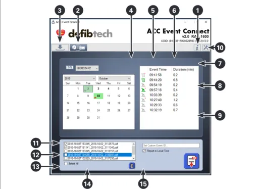
THE DATA EXTRACTION SCREEN
When ACC Event Connect is launched, the Data Extraction Screen will appear as shown in Figure 1. The numbers listed below correspond to the call-outs in this image.1. Help Button.
Clicking on this button calls up a PDF of these instructions.
Selecting an ACC Event Connect Screen
(Data Extraction and Report Generation)
2. Report Generation Screen Tab.
The Report Generation Screen can be accessed at any time by clicking this tab. Details about the functionality of this screen can be found on pages 4-5.
3. Data Extraction Screen Tab.
The Data Extraction Screen covered in this section can be accessed at any time by clicking this tab.
Viewing the ACC Compression Module
Status and General Information
4. Connection Status.
?
Indicates if a USB connection has been established between the Compression Module and the host PC. If connected, a green check mark appears If a connection has not been made, a red “X” appears.
5. Power Status.
?
Indicates power status of a successfully connected Compression Module. If powered on, a green check mark appears. If powered off, a red “X” appears. NOTE: If the Compression Module is running from battery power, it is recommended that the battery charge be at least 20% capacity while using ACC Event Connect.
6. USB Port Connection/Selection.
?
When the Compression Module has been detected, the connected PC COM port is displayed below the USB port icon. If more than one Compression Module is connected to the PC, the user may select which Module is actively connected to the software by changing the PC COM port via the listing shown in the drop-down menu.
7. Refresh Button.
?
Used to retry/refresh the connection to the device.
8. Unit Information Area:
Compression Module.
Shows Compression Module information including serial number, time remaining (in hours and percentage usage) until required maintenance, Module name (if assigned; see item 10 ,“Administrative Settings”), and Module software version number.
9. Unit Information Area: Battery Pack.
Shows information about the current Battery Pack in the Compression Module including serial number, battery charge status, and battery expiration.
Changing Administrative Settings
ACC Event Connect allows the user to customize the Compression Module and the target directory where extracted data and reports are stored.
10. Administrative Settings.
When this button is clicked, a drop-down menu appears (clicking on the button again returns the user to the Data Extraction Screen):
Set Device (Compression Module) Name: This field allows the user to set a custom Compression Module name (60 characters maximum) to the connected Module. Clicking “OK” will store the name USB Port
Figure 1: The
ACC Event Connect
Data Extraction Screen
4 5 6 3 2 1 8 10 7 9 11 12 13 14 15 10
entered to the Module’s memory. This name will now appear in the Compression Module Unit Information Area (8) and on subsequently generated Event Summary Reports (see item C on page 6).
Sync Device (Compression Module) Date/Time: Allows the user to
synchronize the connected Compression Module’s date/time factory settings (GMT) to the date/time set on the host PC. After this button is pressed, a dialog box appears that indicates the difference (if any) between the time/date settings on the Compression Module and those on the host PC. IMPORTANT: Before starting the synchronization process, ensure that the date/time on the host PC is correct. Set File Location: Allows the user to specify the locations on the host PC that extracted data and reports will be stored to. NOTE: Default directories are C:\ACC\ Logs and C:\ACC\Reports.
Restore Default Location: Clicking this button restores the locations on the host PC that extracted data and reports will be stored to as C:\ACC\Logs and C:\ACC\Reports. Manually Load Device (Compression Module) Data: Allows the user to manually load specific extracted data files from C:\ ACC\Logs (or any directory where extracted files have been saved to). NOTE: This function will only appear in the drop-down menu if the user has the Report Generation Screen activated (see item 2 and pages 4-5). In addition, this function can only be used after at least one data extraction from the Compression Module has occurred.
Extracting Data
Select the data types to extract and initiate the extraction process. NOTE: For support purposes, Defibtech recommends that all three data types described below in 11, 12, and 13 be extracted. As such, all three extraction selection checkboxes default as checked.
11. Extract Selection Checkbox:
Configuration.
?
Indicates that configuration files will be extracted when the Extract
Data Button (14) is clicked. NOTE: A configuration data extract will always be performed, no matter what other extract selections are made in the LOG and HISTORY extract selection checkboxes (12, 13).
12. Extract Selection Checkbox: Log.
?
When checked, log files (detailed compression data from
approximately the last hour of
Compression Module operation) will be extracted when the Extract Data Button (14) is clicked. If log files are not desired, uncheck this selection’s checkbox.
13. Extract Selection Checkbox: History
?
.When checked, history files (significant events since the Compression Module was manufactured) will be extracted when the Extract Data Button (14) is clicked. If history files are not desired, uncheck this selection’s checkbox.
14. Extract Data Button.
?
Used to start the data extraction process. When pressed, the types of extract data selected from the checkboxes (11, 12, 13) will be saved to
C:\ACC\Logs (default) or the user-defined directory (see“Set File Location” in item
10. Two green download bars appear above the Extracted Files List (14), indicating progress of the data extraction (the thinner top bar indicates total progress; the thicker bottom bar indicates incremental progress). When data extraction has been completed, both bars will be completely green.
15. Extracted Files List. Any previously
extracted files are shown here. As new extracts are performed, this list will be updated with the additional files. Double-clicking on a desired file from this list will open the contents of C:\ACC\Logs (or the user-defined directory; see“Set File Location” in item 10). The user may then select what to do with any file in the directory using Windows Explorer functionality.
NOTE: Defibtech recommends that
extracted data files not be renamed.
IMPORTANT NOTE: Turn off the
Compression Module when the data extraction process is complete to conserve battery power. Follow the RMU-1000 User Manual steps to prepare the RMU-1000 for clinical use.
Sending Extracted Data to Defibtech
Support (optional)
If necessary (e.g. for service/diagnosis purposes), select extracted data files and attach them to an e-mail to Defibtech support ([email protected]).
For additional assistance, contact Defibtech Customer Service using the contact information on the bottom of page 7. For the latest versions of user documentation or software, visit www.defibtech.com/eventconnect.
Changing Administrative Settings (continued)
Figure 1: The
ACC Event Connect
Data Extraction Screen
4 5 6 3 2 1 8 10 7 9 11 12 13 14 15 10
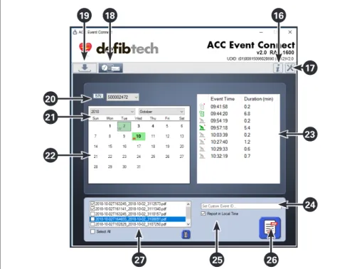
THE REPORT GENERATION SCREEN
At any point after data has been extracted from the ACC’s Compression Module (see pages 2-3), Event Summary Reports (see pages 6-7) can be generated in PDF form using the Report Generation Screen. The numbers listed below correspond to the call-outs in the image shown at right.IMPORTANT NOTE: As certain details that
are stored in the Compression Module’s Log files are removed from those files when they are automatically converted to History files by the device, Defibtech recommends that an Event Summary Report be generated as soon as possible after the ACC is used and before it is utilized for additional events.
16. Help Button.
Clicking on this button will call up a PDF of this set of instructions.
17. Administrative Settings.
When this button is clicked, a drop-down menu appears that allows the user to set the device name, sync date/time, set/reset the location on the host PC where downloaded files are stored, and manually load ACC data. For full details, see item 10 on page 2.
Selecting an ACC Event Connect Screen
(Data Extraction and Report Generation)
18. Report Generation Screen Tab.
The Report Generation Screen covered in this section can be accessed at any time by clicking this tab.
19. Data Extraction Screen Tab.
The Data Extraction Screen can be accessed at any time by clicking this tab. Details about the functionality of this screen can be found on pages 2-3.
Selecting the Event
20. Select Compression Module Serial Number (S/N).
Allows the user to select, by Compression Module serial number, which specific Module’s log files are to be used to generate an Event Summary Report. If logs for more than one device are stored in C:\ACC\Logs(or the user-defined directory; see“Set File Location” in item 10), clicking on this box displays a drop-down menu with all device serial numbers for which data has been extracted and saved to the host PC. If no serial numbers appear in this box, either no data has been downloaded from any device or no data can be found at the specified Logs
directory.
21. Select Event Year and Month.
Two drop-down menus above the calendar (22) allow the user to select which year and month the event took
place that will be represented in the report. NOTE: The drop-down menus will only display years and months for which event data exists at the specified
Logs directory.
22. Select Event Day. Allows the user to
select which day the event took place that will be represented in the report.
• Days for which there is no event data appear in plain type.
• Days with event data appear in bold
type.
• Days that include events with 2+ minutes of compressions are highlighted in green.
• Days with that include events containing device alerts appear with a“W” to the immediate lower left of the date.
Clicking on any date within the calendar will cause the event details box (23) to populate with the event data recorded for that day. Individual events are defined by power on/ off cycles that are separated by 30 seconds or more. In addition, events are sorted by day based upon the compression module’s date/time factory settings (GMT) unless they are altered by the user (see “Sync Device (Compression Module) Date/Time” in Item 10). If the desired event does not appear in a particular day’s event list, check the day before or the day after to see if the event appears in either of those event lists.
23. Select Event.
This table details the specific events associated with the day selected in the
event calendar (22) and allows the user to select a specific event (or series of contiguous events) for inclusion in the Event Summary Report. NOTE: If a series of contiguous events are selected via the select event table, one Event Summary Report that summarizes all of the selected events will be generated. In addition to listing the time of day when each event took place and its duration, icons on the far left side of the table indicate the extracted data file type: log (see item 12) or history (see item 13), if 2+ minutes of compressions are associated with the event, and if one or more device alerts occurred during the event.
Green icons indicate that the event includes 2+ minutes of
compressions; gray icons indicate that the event has fewer than 2 minutes of compressions. If a triangular corner appears to the upper right of either icon, there are one or more device alerts associated with the event.
NOTE: To manually load specific
extracted data files from C:\ACC\Logs
(or the user-defined directory; see“Set File Location” in item 10), use the “Manually Load Device (Compression Module) Data” function that can be accessed via the Administrative Settings drop-down menu (see item 10).
Figure 2: The
ACC Event Connect
Report Generation Screen
19 18 16 23 24 17 20 21 22 25 27 26 (continued on page 5)
Customizing the Event Summary Report
24. Set Custom Event ID. This field allows
the user to assign an event ID that will appear on the header of every page in the Event Summary Report (see item A
on page 6). If an event ID is not entered, this field will show the date the event took place.
25. Report in Local Time. By default, this
box is checked so that all dates/times in the Event Summary Report will be converted to the local PC’s date/time settings. If this is not desired, uncheck this box.
Generating the Event Summary Report
26. Generate Report Button.
After all selections have been made, click the Generate Report Button to generate the Event Summary Report. These reports are stored at C:\ACC\ Reports(or the user-defined directory; see“Set File Location” in item 10). For a detailed overview of a sample report, see pages 6-7.
Managing Event Summary Reports
27. Event Summary Reports List.
As Event Summary Reports are generated, this window displays the filenames of the reports generated during the ACC Event Connect session
(restarting the program will reset the list). Double-clicking on a file from this list will open the contents of C:\ACC\Reports (or the user-defined directory; see“Set File Location” in item 10). To delete any undesired reports, click the box to the left of the report filename, which will result in a checkmark appearing in the box. To delete all displayed reports, click the “Select All” box below the report list
window. Selected files can then be deleted by clicking the Trash Button.
For the latest versions of user documentation or software, visit www.defibtech.com/eventconnect.
Figure 2: The
ACC Event Connect
Report Generation Screen
19 18 16 23 24 17 20 21 22 25 27 26
Page 6 of 7 RAC-U1511EN-BD
EVENT SUMMARY REPORTS
Device Information & Event Summary
A. Header. Appears on the top off all Event
Summary Report pages and includes a custom event ID if one has been set by the user on the Report Generation Screen (see item 24 on page 5) and a custom Compression Module name if one has been assigned (see “Set Device (Compression Module) Name” in item 10
on pages 2-3). NOTE: If an event ID has not been entered, this field will show the date the event took place.
B. General File & Unit Information.
Includes information about the event files that were used in the creation of the Event Summary Report as well as information about the Compression Module that the data was extracted from. The unit information section will include a custom Compression Module name if one has been assigned (see item
10 on page 2,“Administrative Settings”).
C. Event & Compression Summary.
Includes summarized information about the event being reported as well as summarized compression information (if the event included compressions).
D. Compression Ratio Chart. A color-coded
representation of the amount of time during the event that the device was delivering compressions versus protocol and non-protocol pauses. NOTE: This chart will only be included if the event being detailed in the Event Summary Report included compressions.
E. Compression Overview Chart. A
color-coded sequential representation of all compression activity that occurred during the event (i.e. start of compressions, continuous compressions, non-protocol pauses, and end of compressions). This chart is meant to be read starting at the green “start compressions” marker. Compression information then follows in a clockwise sequence until the red “end compressions” marker is reached.
NOTE: This chart will only be included if the event being detailed in the Event Summary Report included compressions.
Event Timeline
F. Event Timeline. Color-coded linear
representation of all compression activity that occurred during the event (i.e. unit power-up, continuous compressions, protocol and non-protocol pauses, and unit power-off). The timeline reads from left to right. Markers below the timeline indicate elapsed event time in one-minute increments. NOTE: This report information will only be included if the event being detailed in the Event Summary Report included compressions.
EVENT SUMMARY REPORT · RMU-1000 EVENT ID · 2018-08-02
DEVICE NAME · ARM-002
GENERATED · 2018-09-20 15:01:36
Device Serial Number · 500002472 Event Start · 2018-08-02 14:42:19 File Type · RML Page 1 of 3 GENERAL FILE INFORMATION
Local Download Time 2018-09-20 15:01:08 UTC Download Time 2018-09-20 19:01:08 Time Difference 04:00:00 RAC-1600 Version 2.0.0.3 Associated Files 500002472_20180920_150112.rmc 500002472_20180920_150112.rmh 500002472_20180920_150112.rml UNIT INFORMATION
Device Name ARM-002
Serial Number 500002472 Manufactured Date 2017-02-15 Software Version 1.109 Lifetime Compressions 7095 compressions
UNIT CONFIGURATION
Compression Rate 101 cpm Compression Depth 2.1 in. Protocol Mode 30:2 Protocol Breath 1.5 seconds Continuous Breathing 8 breaths/minute
EVENT SUMMARY
Start Date (Local) 2018-08-02 14:42:19 End Date (Local) 2018-08-02 14:50:20 Total Event Duration 00:08:01 Warning(s) 2
COMPRESSION SUMMARY
Total Active Time 00:07:37 Compressions 495 Time Compressing 00:04:55 (65%) Time Paused 00:02:41 (35%) Longest Pause 00:02:17 Pauses > 10 seconds 1 Pauses > 20 seconds 1 Avg Compression Depth 2.1 inches Avg Compression Rate 101 cpm
COMPRESSION OVERVIEW COMPRESSION RATIO
Compression Fraction 65% LEGEND A B D C E
EVENT SUMMARY REPORT · RMU-1000 EVENT ID · 2018-08-02
DEVICE NAME · ARM-002
GENERATED · 2018-09-20 15:01:36
EVENT TIMELINE
EVENT TIMELINE LEGEND
Detailed Event Information
G. Event Information. Detailed
time-stamped listing of event information from start-up of the device to unit shutdown. Also includes device serial number and battery charge levels at the start and the end of the event. If the event detailed in the Event Summary Report includes any device alerts, they will appear in bold type.
For the latest versions of user documentation or software, visit www.defibtech.com/eventconnect.
For additional assistance, contact Defibtech Customer Service using the contact information below.
RAC-U1511EN-BD Page 7 of 7
EVENT SUMMARY REPORT · RMU-1000 EVENT ID · 2018-08-02
DEVICE NAME · ARM-002
GENERATED · 2018-09-20 15:01:36
Device Serial Number · 500002472 Event Start · 2018-08-02 14:42:19 File Type · RML Page 3 of 3 EVENT INFORMATION
TIME (LOCAL) DEVICE EVENT EVENT DATA
2018/08/02
14:42:19 STARTUP 14:42:19 POWER BUTTON 14:42:19 BATTERY PLUGGED IN
BATTERY SERIAL NUMBER 550001120 BATTERY CHARGE 78% 14:42:21 ADJUST DOWN BUTTON
14:42:39 ADJUST DOWN BUTTON 14:42:45 RUN CONTINUOUS 14:45:14 PAUSE BUTTON 14:45:16 ADJUST UP BUTTON 14:45:25 RUN PROTOCOL
14:45:26 WARN - MOTOR NEEDS POSITION ADJUSTMENT
14:45:30 ADJUST UP BUTTON 14:45:30 ADJUST UP BUTTON 14:45:31 ADJUST UP BUTTON 14:47:25 RUN PROTOCOL
14:47:25 WARN - MOTOR NEEDS POSITION ADJUSTMENT
14:47:28 ADJUST DOWN BUTTON 14:47:29 ADJUST DOWN BUTTON 14:47:30 ADJUST DOWN BUTTON 14:47:34 RUN PROTOCOL 14:49:54 RUN CONTINUOUS 14:50:15 POWER BUTTON 14:50:16 UNIT SHUT DOWN 14:50:20 HIBERNATION
BATTERY SERIAL NUMBER 550001120 BATTERY CHARGE 73%
G
Y Y Y Y
Information in this document is subject to change without notice. Copyright © 2018 Defibtech, L.L.C.
All Rights Reserved. For patent information, see
www.defibtech.com/support/patents.
Defibtech, L.L.C.
741 Boston Post Road, Suite 201 Guilford, CT 06437 • USA
Web: www.defibtech.com
Tel: 1-(866)-333-4241 (toll-free within North America) • 1-(203) 453-4507
Email: [email protected] (service and repair); [email protected] (sales)
ELECTRONIC DISTRIBUTION