Public Utility Commission of Texas
Prepared by:
Distributed Utility Associates Endecon Engineering 1062 Concannon Blvd. 347 Norris Court
Livermore, CA 94550 San Ramon, CA 94583
925-447-0604 925-552-1330
[email protected] www.endecon.com
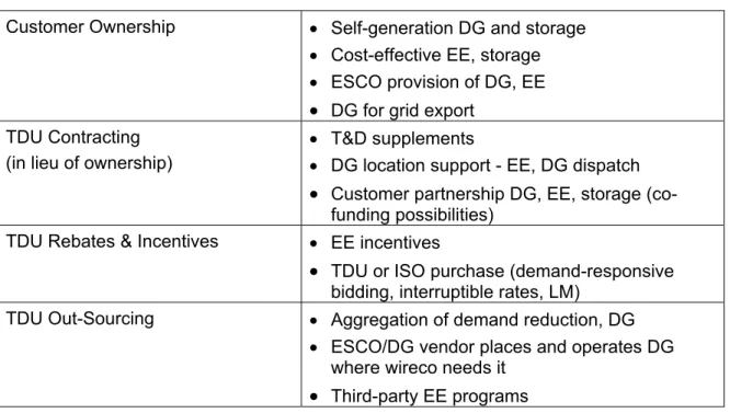
May 1, 2002
U.S. Department of Energy
TABLE OF CONTENTS
1. Introduction ... 1-1 2. Safety Requirements... 2-1 2.1. PUCT Rules ... 2-1 2.2. TNRCC Rules ... 2-1 2.3. Local Codes and Standards ... 2-2 2.4. National Codes and Standards ... 2-2 2.4.1. National Fire Protection Association... 2-2 2.4.2. Institute of Electrical and Electronics Engineers (IEEE) ... 2-3 2.4.3. Underwriters Laboratories ... 2-4 3. Technical Summary... 3-1 3.1. General ... 3-1 3.2. Prevention of Interference ... 3-1 3.3. Requirements... 3-2 4. TDU Analyses of DG Interconnections... 4-1 4.1. Utility Processing of DG Applications ... 4-1 4.2. DG Interconnection Requirements Review ... 4-7 4.2.1. DG Application Review... 4-7 4.2.2. Distribution System Type Review ... 4-7 4.2.3. Network Secondary Review... 4-8 4.2.4. Non-Network Review... 4-11 4.2.5. Issues That May Require Additional Review ... 4-13 4.3. Cost/Benefit Impacts of DG... 4-14 4.3.1. TDU Benefits and Costs ... 4-14 4.3.2. Customer Benefits and Costs ... 4-19 4.3.3. Other Benefits and Costs ... 4-24 4.4. Operational Protocols... 4-27 5. DG Applicant information ... 5-1 5.1. DG Applicant Rights and Responsibilities ... 5-1 5.2. TDU Rights and Responsibilities... 5-2 5.3. Interconnection Process... 5-3 5.4. Frequently Asked Questions (FAQs) About DG Interconnections... 5-4 6. Energy Efficiency and Customer-Owned Resources ... 6-1 7. Pre-certification Process ... 7-1 8. Interconnection Disputes... 8-1 Appendix A1: Definitions ... A1-1 Appendix A2: Copy of PUCT’s Rules, Forms and PURA 99 Excerpts ... A2-1 Appendix A3: Summary of DG Technologies ... A3-1 Appendix A4: Texas Utility Contacts ... A4-1 Appendix A5: Internet Links ... A5-1 Links for Electric Distribution Companies in Texas ... A5-2 Appendix A6: Additional Safety and Performance References ... A6-1 Appendix A7: Pre-Certification Requirements ... A7-1 Revisions to the Manual ... A7-10
1. INTRODUCTION
The Public Utility Commission of Texas (PUCT) has prepared this manual to guide the inclusion of distributed generation into the Texas electric system. It is intended for use by utility engineers processing distributed generation interconnection applications, as well as those persons considering or proposing the interconnection of distributed generation with a transmission and distribution utility (TDU). While every possible eventuality or circumstance cannot be anticipated, the procedures in this manual should cover most important issues or problems, including a process for prompt dispute resolution.
Texas’ Public Utility Regulatory Act (PURA) of 1999 included in the list of customer rights and safeguards that “A customer is entitled to have access… to on-site distributed generation…” [§39.101(b)(3)]. This provision led the PUCT in October 1999 to adopt Substantive Rules §25.211 and §25.212 addressing the technical and procedural aspects of interconnecting distributed generation, developed through a collaborative process among the members of the TDU and DG communities. This manual also includes the more recently adopted rules on operational aspects and environmental treatment of distributed resources.
The Public Utility Commission of Texas wants to encourage the use of distributed resources. Distributed resources benefit the state by adding more competitive options, potentially reducing customer energy, improving the asset utilization of TDU distribution systems, firming up reliability, and improving customers’ power quality. Texans have the right to use distributed resources for whatever purpose they feel is beneficial and it is the responsibility of the local distribution utilities to accommodate and interconnect distributed generation subject to the rules laid out here.
The philosophy used to develop this manual was that distributed resources will and should be an integral and valued part of the Texas electric supply system. Wherever possible Texas has simplified the process, contractual relationships and hardware required to interconnect distributed resources safely and beneficially for all involved parties.
Joint funding for the preparation of this manual was provided by the U.S. Department of Energy Office of Energy Efficiency and Renewable Energy and the Public Utility Commission of Texas.
2. SAFETY REQUIREMENTS
This section reviews the variety of interconnection-related safety requirements that the DG designer/installer and the utility must take into consideration. The requirements are divided by jurisdiction: State (PUCT), local, and national. These requirements are intended to ensure that DG is designed and installed in a way that
• is not a safety hazard to utility personnel or equipment or to other customers, • does not disturb other customers or degrade the quality of the distribution
system,
• provides reliable service to the DG owner and the utility.
To make certain that these expectations are met, it is critical that the TDU understand the characteristics and requirements of the DG and vice versa.
2.1. PUCT Rules
State regulations regarding the generation, transmission, and distribution of electricity are set by the Public Utility Commission of Texas (PUCT). The PUCT’s Web site provides access to all Rules at http://www.puc.state.tx.us under “Rules and Laws”. Of technical interest to DG are the following:
Substantive Rules - Chapter 25
Applicable to Electric Service Providers Subchapter A General Provisions §25.5 * Definitions
Subchapter C Quality of Service §25.51 Quality of Service.
Division 2. Transmission and Distribution Applicable to All Electric Utilities §25.211 * Interconnection of On-Site Distributed Generation
§25.212 * Technical Requirements for Interconnection and Parallel Operation Of On-Site Distributed Generation
The specific requirements of §25.211 and §25.212 are covered in subsequent sections of this manual. These rules detail the operational responsibilities of both the TDU and the applicant.
The PUCT's rules may, in some cases, be superseded by local requirements or modified in the future.
2.2. TNRCC Rules
A distributed generation emissions rulemaking is in progress. This subsection will be updated after a DG emissions rule is adopted by TNRCC.
2.3. Local Codes and Standards
County and city regulations may place additional permit or building code restrictions or requirements on DG systems. These requirements will primarily affect the DG installer, but both the installer and the utility should be aware of local codes and standards that might modify the interconnection requirements specified in the PUCT Rules.
2.4. National Codes and Standards
To address safety and power quality issues, national codes and safety organizations have developed guidelines for equipment manufacture, installation and operation. The major code and safety organizations that apply to distributed generation are the National Fire Protection Association (NFPA), Underwriters Laboratories (UL) and Institute of Electrical and Electronics Engineers (IEEE). Each of these organizations covers different aspects of the DG interconnection in the context of their organizational missions, as explained below.
The national laboratories are also actively involved in issues surrounding DG interconnection. The Department of Energy’s National Renewable Energy Laboratory (NREL) in Golden, Colorado and Sandia National Laboratories in Albuquerque, New Mexico work closely with the NFPA, IEEE and UL on code issues and are frequently involved in equipment testing. The labs are not responsible for issuing or enforcing codes, but they do serve as valuable sources of information on DG and interconnection issues. The following subsections discuss each of these standards bodies individually, how the codes interact, and how the documents are being used. A good deal of TDU interconnection work has been done in the renewables arena, primarily PV. Several of the documents listed are PV-specific, but in fact, are relevant to any inverter-based technology and touch on issues that apply to rotating machines as well.
2.4.1. National Fire Protection Association
The National Fire Protection Association publishes NFPA-70, The National Electrical Code (NEC), and is the foremost organization in the U.S. dealing with electrical
equipment and wiring safety. The scope of the NEC covers all buildings and property except for electric TDU property, i.e., all equipment on the customer’s side of the point of common coupling (the meter).
Article 705, Interconnected Electric Power Production Sources, broadly covers DG interconnection. It reinforces many of the topics covered in the PUCT Rule (e.g., “Synchronous generators in a parallel system shall be provided with the necessary equipment to establish and maintain a synchronous condition”) and adds some
details, for example, related to disconnect switch requirements.
Article 690, Solar Photovoltaic Systems, mentions interconnection to the grid, but focuses more on system wiring and descriptions of components. One key requirement in Article 690 of the NEC is that all equipment interconnecting with the grid must be listed1. This requirement is unique both within the code (which primarily encourages rather than requires listed equipment) and within DG. Inverters for a microturbine or fuel cell (which are not explicitly covered by 690) do not have to be listed per the code, though it’s nearly always required by electrical inspectors.
The NEC may address fuel cells or utility interconnection issues related to all inverter-based in the future.
Additional relevant standards are found in NFPA-37, the Standard for the Installation and Use of Stationary Combustion Engines and Gas Turbines; NFPA-99, the Standard for Health Care Facilities; and NFPA-110, the Standard for Emergency and Standby Power Systems.
2.4.2. Institute of Electrical and Electronics Engineers (IEEE)
The standards that electric utilities adopt for their equipment often originate from IEEE. Standards balloting rules require that a balanced committee of utilities, manufacturers, users, and general interest groups are involved in the development of new IEEE standards. This diversity ensures that the standards provide a consensus of all interested parties. IEEE standards are voluntary, so utilities are not required to adopt them unless there is a specific Commission or legislative ruling to that effect.
In the 1980s, the Institute of Electrical and Electronics Engineers (IEEE) published ANSI/IEEE Std 1001-1988, IEEE Guide for Interfacing Dispersed Storage and Generation Facilities with Electric Utility Systems. This standard addresses the
basic issues of power quality, equipment protection, and safety. This document has expired and a new document is under development to take its place. This project, P1547, Standard for Distributed Resources Interconnected with Electric Power Systems, was started in 1998 and will be completed 2001.
The recently adopted ANSI/IEEE Std. 929-2000, IEEE Recommended Practice for Utility Interface of Photovoltaic (PV) Systems, was developed to meet utility
concerns with safety and power quality for PV systems. The intent was that there 1 As defined in NEC Article 100, listed means “equipment, materials, or services included in a list
published by an organization that is acceptable to the authority having jurisdiction and concerned with evaluation of products or services, that maintains periodic inspection of production of listed equipment or materials or periodic evaluation of services, and whose listing states that either the equipment, material, or services meets identified standards or has been tested and found suitable for a specified purpose.”
would be no need for additional requirements in developing utility-specific guidelines,
especially for systems of 10 kW or less. The new Std. 929, replacing a 1988 version, contains a 12-page recommended practice and appendices with detailed background into issues such as how inverters interface with the utility, islanding, and distribution transformers.
Another key standard is IEEE 519-1992, IEEE Recommended Practices and Requirements for Harmonic Control in Electric Power Systems. This guide applies
to all types of static power converters used in industrial and commercial power systems, and addresses the problems involved in the harmonic control and reactive compensation of such converters. Limits of disturbances to the AC power distribution system that affect other equipment and communications are recommended. Voltage and current harmonics limits—total and single harmonic— as well as the voltage flicker limits of irritation curves are referenced for both utility practice and DG requirements.
IEEE standards covering many aspects of utility interconnection and distribution system design and operation are listed in Appendix A6.
2.4.3. Underwriters Laboratories
Underwriters Laboratories (UL) is a private, not-for-profit organization that has evaluated products, materials and systems in the interest of public safety since 1894. UL has become the leading safety testing and certification organization in the U.S., and its label is found on products ranging from toaster ovens to inverters to some office furniture.
Although UL writes the testing procedures, other organizations may do the actual testing and certification of specific products. In addition to UL, other testing labs such as ETL SEMKO (ETL), and the Canadian Standards Association (CSA) are widely recognized listing agencies for electrical components.
UL Standard 1741, Static Inverters and Charge Controllers for use in Photovoltaic Power Systems, deals with design requirements and testing procedures for
inverters. UL 1741, published in May 1999, is now being revised comport to IEEE Std 929-2000, to cover inverters used for sources other than PV and to cover controllers that might provide similar capabilities for synchronous and induction machines.
3. TECHNICAL SUMMARY
3.1. GeneralTechnical requirements for interconnecting DG to the TDU are defined in §25.212. This section summarizes those requirements. In general, the applicant’s generation and interconnection equipment must meet all applicable federal, state and local codes. Interconnection equipment shall be capable of providing TDU system protective functions to prevent the generator from energizing a de-energized circuit owned by the TDU. Use of pre-certified equipment (see Section 7 of this Manual) will ensure that the minimum required capabilities are met, so the TDU will not need to review the DG design (other than to ensure that all necessary equipment is included).
Many of the requirements listed here were developed for non-export systems: those that do not intentionally send power to the TDU across the point of common coupling. The non-export condition can be met either implicitly by establishing that the DG output capacity is less than the applicant’s verifiable minimum load (i.e., the DG never generates more than the applicant will consume), or explicitly through the use of a reverse power or under power relay (devices that disconnect the DG from the TDU if it attempts to export power)2. Systems that export power can place additional burden on the distribution system, especially a networked secondary, but may provide benefits as well. The TDU may elect to study these systems or any application that they feel would present safety or operational hazards to the distribution system. The results of the study may be a requirement for more sophisticated protective devices and operating schemes. However, the burden is on the TDU to justify the need for any additional requirements. The applicant has the option of complying with the additional requirements, withdrawing the application, or petitioning the commission for a good cause exception.
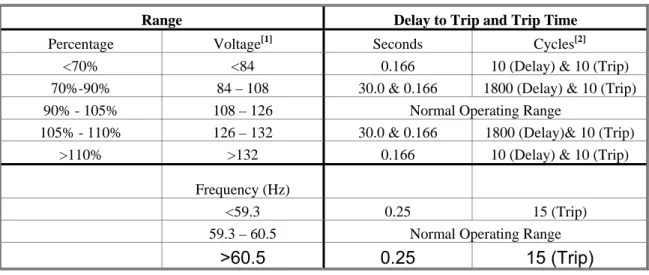
3.2. Prevention of Interference
Many of the requirements established in Rule §25.212 are based on the assumption of relatively low DG penetration operating from the TDU. Rather than attempting to regulate voltage and frequency, the DG should follow the voltage and frequency imposed by the TDU, and should disconnect under abnormal conditions as defined in Table 3-1 below. Since the DG is not regulating voltage or current, the allowable operating ranges are relatively wide. The ranges and trip times shown in Table 3-1 take into account the fact that losing any generation (including DG) when the system voltage or frequency is decreasing can exacerbate generation-related problems. After tripping due to a voltage or frequency disturbance, the DG may reconnect once the utility voltage and frequency have returned to the Normal Operating Range and 2 This may be a discrete relay or a function of a controller or inverter. Throughout this document, the
have stabilized for 2 minutes or a shorter time as agreed to by the applicant and TDU.
Table 3-1: Voltage/Frequency Disturbance Delay & Trip Times
Range Trip Time[2]
Percentage Voltage[1] Seconds Cycles
<70% <84 0.166 10 (Delay) & 10 (Trip)
70%-90% 84 – 108 30.0 & 0.166 1800 (Delay) & 10 (Trip)
90% - 105% 108 – 126 Normal Operating Range
105% - 110% 126 – 132 30.0 & 0.166 1800 (Delay) & 10 (Trip)
>110% >132 0.166 10 (Delay) & 10 (Trip)
Frequency (Hz)
<59.3 0.25 15 (Trip)
59.3 – 60.5 Normal Operating Range
>60.5 0.25 15 (Trip)
[1] Voltage shown based on 120V, nominal.
[2] Trip times for voltage excursions were added for completeness by the PUCT Project No. 22318 Pre-certification Working Group as the intent of 25.212.
As with load, minimum harmonics and flicker standards are defined for DG. These limits are established in IEEE 519. In summary, this standard, in Chapter 10 for individual consumers, requires current total demand distortion (TDD) of 5% or less of the fundamental. The standard, in Chapter 11 requires voltage total harmonic distortion (THD) of 5% or less and 3% for any single harmonic, measured at the point of common coupling. Described in Chapter 10 of the standard, flicker, typically associated with induction generator start-up, may not cause a voltage dip of more than 3% as indicated on the border lines of irritation curve of the standard.
3.3. Requirements
Table 3-2 summarizes Texas’ equipment and operational requirements for interconnecting DG, based on the characteristics of the proposed system. These requirements are first differentiated by DG paralleling mode and type of connection. Closed Transition is a mode of operation in which the DG is operated in parallel with the TDU for brief period of time, only long enough to ensure that the load is maintained while transitioning from TDU supply to generator, or vice versa. A manufacturing facility looking for peak shaving, but with power quality-sensitive processes, might use this type of system. For such systems, defined here as paralleling for less than 60 cycles (one second), the potential impact on the distribution system, and thus the interconnection requirements, are minimal.
of anticipated DG systems—are listed by connection type: single- or three-phase. Table 3-2: DG Interconnection Requirements
Closed Trans-ition Single-Phase Three-Phase Capacity Feature ≤10 MW ≤50 kW ≤10 kW 10 kW -500 kW 500 kW -2 MW 2 MW -10 MW PUCT Rule Reference §25.212
(g) §25.212(d) §25.212(e) (3)(A) §25.212(e)(3) (B) §25.212(e) (3)(C) §25.212 (e)(3)(D) Interrupting devices (capable of interrupting maximum available fault current)
9
9
9
9
9
[4]Interconnection disconnect device (manual, lockable, visible, accessible)
9
9
9
9
9
9
Generator disconnect device9
9
9
9
9
9
Over-voltage trip9
9
9
9
9
9
Under-voltage trip9
9
9
9
9
9
Over/Under frequency trip
9
9
9
9
9
9
Synchronizing check (A: Automatic, M: Manual)
A A/M [1] A/M [1] A/M [1] A
[1] A [1] Ground over-voltage or over-current trip [2] [2] [2] [2]
Reverse power sensing [3] [3] [3]
If exporting, power direction function may be used to block or delay under frequency trip
9
9
Automatic voltage regulator [1]
Telemetry/transfer trip
9
Notes:
9– Required feature (blank = not required)
[1] – Required for facilities with stand-alone capability
[2] – May be required by TDU; selection based on grounding system
[3] – Required, unless generator is less than applicant minimum load, to verify non-export [4] – Systems exporting shall have either redundant or listed devices
Single-phase systems will primarily be used on residential or small commercial applications. For closed transition and single-phase DG, Table 3-2 lists the maximum allowable system size. For three-phase DG, the requirements are further broken down by DG capacity, with larger systems having more requirements than smaller systems.
A few additional requirements apply for three-phase generators, by device type: Synchronous Machines:
• Three phase circuit breakers with electronic or electromechanical control. • Applicant solely responsible for proper synchronization.
• Excitation response ratio shall not be less than 0.5. • Excitation system shall conform with ANSI C50.13-1989. Induction Machines
• May “motor” up to speed if initial voltage drop at the PCC is within the Flicker limits (§25.212(c)(2)).
Inverters
• Line-commutated inverters do not require synchronizing equipment. • Self-commutated inverters require synchronizing equipment.
4. TDU
ANALYSES OF DG INTERCONNECTIONS
IntroductionThis section is intended to provide a systematic approach for the engineering review process of a typical interconnection study. It includes the steps that must be taken to properly account for site-specific concerns and address the technical and procedural requirements of the Texas interconnection rules §25.211 and §25.212.
The goal of this section is to ensure that TDU interconnection analyses of the impacts of distributed generation are conducted in a clear, unbiased and consistent manner, irrespective of the TDU, the DG technology, or the applicant. This section will give the DG applicant a clear understanding of how the interconnection analysis will be conducted. It also provides a method to determine whether a DG configuration and application will pass or fail Texas’ analytical protocols. The analytical directions in this section should allow all members of Texas’ TDU and DG communities to use common terms, descriptions and assumptions about the benefits, costs, and grid impacts of DG, so that any disputes about a specific interconnection will focus on whether the proper calculations have been made, rather than whether a specific impact or benefit is legitimate or valid.
However, certain applications may require minor modifications while they are being reviewed by the TDU. Such minor modifications to a pending application shall not require that it be considered incomplete and treated as a new or separate application.
4.1. Utility Processing of DG Applications
As defined in §25.211, upon receipt of a completed application, the TDU has a defined period (4 to 6 weeks, defined below) of time in which to process the application and provide the following:
• Approval to interconnect
• Approval to interconnect with a list of prescribed changes to the DG design • Justification and cost estimate for prescribed changes to TDU system • Application rejection with justification
The PUCT limits when and why a TDU may charge the applicant for the performance of a service, coordination, or system impact study. In general, any study performed by the TDU shall follow these rules:
• Study scope shall be based on characteristics of the DG at the proposed location.
• Study shall consider cost incurred and benefits realized as a result of DG interconnection.
• TDU shall provide a cost estimate to the DG applicant prior to initiation of study.
• TDU shall make written reports and study results available to the DG applicant.
• TDU may reject application for demonstrable reliability or safety issues but must work to resolve those issues.
• TDU shall advise the DG applicant of potential secondary network-related problems before charging a study fee.
• TDU shall use best reasonable efforts to meet the application processing schedule, or will notify the DG applicant in writing why it cannot meet the schedule and provide estimated dates for application processing and interconnection.
If the proposed site is not on a networked secondary no study fee may be charged to the applicant if all of the following apply:
• Proposed DG equipment is pre-certified • Proposed DG capacity is 500kW or less
• Proposed DG is designed to export no more than 15% of the total load on feeder (based on the most recent peak load demand)
• Proposed DG will contribute not more than 25% of the maximum potential short circuit current of the feeder
Certain aspects of secondary network systems create technical difficulties that may make interconnection more costly to implement. If the proposed site is serviced by a networked secondary, no study fee may be charged to the applicant if:
• Proposed DG equipment is pre-certified
• Aggregate DG, including the proposed system, represents 25% or less of the total load on the network (based on the most recent peak load demand)
and either
• Proposed DG has inverter-based protective functions, or
• Proposed DG rating is less than the local applicant’s verifiable minimum load. Otherwise, the TDU may charge the DG applicant a fee to offset the costs of the interconnection study. The TDU must advise applicants requesting DG interconnection on secondary networks about the potential problems and costs before initiating the study.
Note that these provisions do not preclude the TDU from performing a study; they simply regulate when the TDU can charge the applicant for the cost of the study. Whether or not a study fee is billable to the applicant, the TDU may reject an application for demonstrable reliability or safety issues but must work to resolve
those issues to the mutual satisfaction of the TDU and applicant. The TDU must make reasonable efforts to interconnect all proposed DG, including the possibility of switching network-secondary service to a radial feed if practical and if acceptable to the applicant.
The flow charts in Figures 4-1 and 4-2 show, for non-network and secondary network systems respectively, how the Rule §25.211 requirements interact and what the TDU must consider when processing a DG interconnection application. Some of the decisions are based on location-specific information not available to the DG applicant at the time of application. It is important that the application be accurate and complete to eliminate delays in processing. These decision paths result in either “Approve Application” or “Recommendation”.
Systems meeting the requirements that result in “Approve Application” are considered simple with little chance of being a hazard to the distribution system, personnel, or neighboring customers. These systems should not require any additional studies, thus the utility is not allowed to charge a study fee.
The Recommendation results from a study that may be charged to the applicant, and may be one of the following:
• Approval of the application as is
• Description of changes to the proposed DG system or to the distribution system necessary to approve the application
• Rejection of the application due to specified reasons
Figure 4-3 provides a timeline of activities, based primarily on the requirements in §25.211(m) . Normally, it is anticipated that the application will be submitted, processed, and an interconnection agreement signed before construction activities begin. However, the Rules do not require this sequence and a more compressed schedule is possible. Rule §25.212(h) requires the DG applicant to provide the utility with two-week notice prior to start-up testing. However the Rules do not specify when this must occur or which events must precede the notice. An applicant can anticipate approval, submit the two weeks notice along with the application and be prepared for start-up testing immediately upon signing the interconnection agreement. If utility system modifications are required that are not considered a substantial capital upgrade, the utility may have to complete those upgrades prior to the start-up test.
If the utility is unable to complete the modifications prior to commissioning (for example, if the two week notice is given with the application), they may work out partial operation or other arrangements with the applicant until such modifications can be completed. Rule 25.211(m)(4) allows the utility extra time to interconnect the DG if it can show suitable reasons for needing an extension to the time allowed.
Figure 4-1: Non-Network Study Chart
No
Study Fee Allowed (g-2) No No No Yes Yes Yes Yes Recommendation Approve Application Equipment Pre-certified? (g-1) DG ≤500 kW? (g-1) Export ≤15% of Feeder Load ? (g-1) DG ≤25% of Max Short Circuit? (g-1) Proposed System on Non-Network Feeder (g)
No Study Fee Allowed (g-1)
No
Study Fee Allowed (g-2) No No No Yes Yes Yes Yes Recommendation Approve Application Equipment Pre-certified? (g-1) DG ≤500 kW? (g-1) Export ≤15% of Feeder Load ? (g-1) DG ≤25% of Max Short Circuit? (g-1) Proposed System on Non-Network Feeder (g)
No Study Fee Allowed (g-1)
(References, in parentheses, indicate the appropriate section of Rule §25-211.)
Figure 4-2: Network Secondary Study Chart
No
Study Fee Allowed (g-2, m-1) No No No Yes Yes Yes Yes Recommendation Approve Application Equipment Pre-certified?(?) Aggregate DG ≤ 25% of Feeder Load? (h-1, h-2) Inverter-based Protective Function ? (h-1) DG < customer minimum load? (h-2) Proposed System on Network Secondary (h,i)
No Study Fee Allowed (g-2, m-1) DG < 20kW, Inverter based? (i) No Yes No
Study Fee Allowed (g-2, m-1) No No No Yes Yes Yes Yes Recommendation Approve Application Equipment Pre-certified? (?) Aggregate DG ≤ 25% of Feeder Load? (h-1, h-2) Inverter-based Protective Function ? (h-1) DG < customer minimum load? (h-2) Proposed System on Network Secondary (h,i)
No Study Fee Allowed (g-2, m-1) DG < 20kW, Inverter based? (i) No Yes (References, in parentheses, indicate the appropriate section of Rule §25-211.)
Figure 4-3: Application Processing Activities
S
Suubmit Abmit Appppllicationication
IInncocomingming PPrrocesocesssiingng InInssttaallll DDGG Up
Upgrgradadee
M
Miinimum Ennimum Enggiineerinneeringg ReRevviiewew ReReqquuirireedd Optiona
Optionall SSttududyy
Up
Upggrradeade YeYess Applic
Applicationation
S
Suubstbstaantntiaiall
Allowable Time*Allowable Time*Allowable Time*
Re Rejecjectteded
??
Substa Substantntiaiall A
Appplicaplicattionion NoNo UUppggrrade Conade Conttrraactct Ap
Apprproveovedd 2211(11(mm))(3(3))
2 wee2 wee kk notice notice 22 12(12( hh ))
IInntetercrconneconnectiontion
Agre Agreeemmeenntt Si
Signgneedd 21211(1(e)e)((55))
Co
Commmmiissiossionniinngg TTeestst
Oper
Operaatte De DGG
Up Upggrradeade
Dist
Distriributibutionon Sy Syssttemem
* -- Allowable Time from receipt of completed application to a signed interconnection agreement: 1) Systems using Precertified equipment – 4 weeks (§25.211(m)(1))
2) Systems using Non-precertified equipment – 6 weeks (§25.211(m)(2))
3) Add up to 6 weeks for additional interconnection study time for applications in Network secondaries where the aggregate DG exceeds 25% of the feeder load. (§25.211(h)(3)) 4) If the proposed system will require substantial capital upgrades to the utility system, the utility
shall provide the applicant an estimate of the schedule and applicant’s cost, if any, for the upgrade. If the applicant desires to proceed with the upgrade, the applicant and the utility will enter into a contract for the completion of the upgrade. The commissioning test will be allowed within two weeks following the completion of such upgrades. (§25.211(m)(3)). 5) The TDU shall use best reasonable efforts to interconnect facilities within the time frames
described above. If in a particular instance, the TDU determines that it cannot interconnect a facility within these time frames, it will notify the applicant in writing. The notification will identify the reason or reasons interconnection could not be performed in accordance with the schedule and provide an estimated date for interconnection (§25.211(m)(4)).
4.2. DG Interconnection Requirements Review
The discussion below lays out when a TDU is authorized by the PUCT Rules to charge for a DG Interconnection Study, and provides some guidance as to how a study should be performed. Rule language does not preclude the TDU from performing a study at anytime, limiting only when the applicant may be billed for the study. However, it is expected that as each TDU gains experience with DG on its system, the TDU will reduce its reliance on studies as well as the level of effort necessary to perform them.
4.2.1. DG Application Review
The DG applicant should provide all necessary information with the application, including documentation verifying compliance with the technical requirements of Rule 25.212. Failure to supply all necessary information is grounds for rejection of the application.
The following information must be supplied for the application package to be viewed as complete.
1. DG generator or inverter nameplate capacity in kilowatts (DGCapacity)
2. Maximum DG capacity allocated for export in kilowatts (DGExport)
3. DG Output (voltage, single-phase or three-phase) 4. DG type (e.g. inverter-based, synchronous, induction) 5. DG short circuit capability (DGSCmax)
6. Whether the DG facility meets the Texas pre-certification requirements (see Section 7 of this Manual)
7. Location of DG (street address, applicant account number) 8. Minimum load of the facility to which the DG is connected.
9. Documentation that the DG facility contains all the minimum protective functions required in Rule §25.212 (see Table 3-2).
10. Documentation that the appropriate protective functions are either factory preset to proper values or are capable of being set according to the parameters set forth in Rule §25.212 (see Table 3-1).
4.2.2. Distribution System Type Review
Once the application package is complete, the TDU should determine whether the proposed DG installation site is on a secondary network by locating the proposed facility on its distribution circuit. The answer to this question will impact the type of review process and study fees and schedules associated with the application.
Q: Is the proposed DG facility to be located on a networked secondary distribution system?
If yes, proceed to section 4.2.3: Secondary Network Review. If no, proceed to section 4.2.4: Non-Network Review.
4.2.3. Network Secondary Review
In a network secondary distribution system, service is redundantly provided through multiple transformers as opposed to radial systems where there is only one path for power to flow from the distribution substation to a particular load. The secondaries of networked transformers are connected together to provide multiple potential paths for power and thus much higher reliability than an equivalent radial feeder. To keep power from inappropriately feeding from one transformer back through another transformer (feeding a fault on the primary side, for example), devices called network protectors are used to detect such a backfeed and open very quickly (within a few cycles).
If the aggregate DG output within a networked secondary exceeds the aggregate load, the excess power will activate one or more network protectors. If such a situation were allowed, the reliability of the secondary network would be reduced. In such a circumstance, DG could compromise grid reliability.
Most downtown areas of larger cities have secondary networks (e.g., Austin, Dallas, Houston and San Antonio). How far those networks extend and where the network ends and radial distribution begins is a function of the density of the load and a number of other factors. Facilities in the center of downtown areas are very likely to be on networks, whereas facilities in suburban and rural areas are almost certain to be on a radial distribution system.
4.2.3.1. DG Pre-Certification Review – Secondary Network
If the DG qualifies as pre-certified under Texas' pre-certification requirements (Rule §25.211(c)(12) and §25.211(k); see section 7 of this manual), the review can proceed to the DG Capacity Review. If the DG does not qualify as pre-certified, the TDU is allowed up to six weeks to perform a study that may involve a fee.
4.2.3.2. DG Capacity Relative to Load – Secondary Network
Secondary networks are used where load is sufficiently dense to justify the added reliability and added cost of such a system. As a result, the DG facility (or aggregate DG) could be sizeable before the utility engineer needs to be concerned. For example, one-megawatt of DG on a 10-megawatt network would be of little concern.
Conversely, one-megawatt of DG on a three-megawatt network could be of significant concern.
Rule §25.211(h)(1) and (2) define when the TDU shall approve applications for interconnection (the TDU may elect to do a study but may not charge a fee). These are as follows:
• §25.211(h)(1): Distributed generation facilities that use inverter-based protective functions with total distributed generation (including the new facility) on the affected secondary network representing no more than 25% of the total load of that network.
• §25.211(h)(2): Other on-site generation facilities whose total generation is less than the local customer's load (non-export) and with total distributed generation (including the new facility) on affected secondary network representing no more than 25% of the total load of that network.
The aggregate DG is determined by summing the nameplate ratings of each of the DG units within the network. The total load of the network is defined as the maximum load of the network for the previous 12-month period. This threshold, expressed in equation form, is the following:
TotalDGCapacity network = TDGC network ≤ 0.25×TotalLoadnetwork
This is the value at or below which inverter-based DG should not require costly changes to the utility system in order to accommodate the DG installation. The TDU shall accept applications, and a study fee may not be charged since it is assumed that no study is necessary. It is assumed that all inverter-based DG under 20kW is so small that, irrespective of the 25% threshold, no study is necessary and therefore the application shall accepted and no study fee may be charged.
4.2.3.3. Power Export Review
To determine whether or not a distributed generator complies with §25.211(h)(2) above, it must be determined whether the DG will export power. No export limit was provided for network systems, meaning that all export systems on network secondaries may be subject to a study for which a fee may be charged (excluding inverter-based systems).
A DG system designed for non-export (i.e., it only offsets applicant load without feeding into the grid) simplifies the review process. Non-export systems will not adversely impact the secondary network protection schemes and, for systems with explicit non-export capabilities, the need for additional islanding detection is eliminated. There are three methods to ensure that power is not exported:
(1) (Implicit) To ensure no export of power without the use of explicit non-export protective functions, the capacity of the DG must be no greater than the customer’s verifiable minimum annual load. Use of additional anti-islanding functions may be required to ensure worker and equipment safety.
(2) (Explicit) To ensure power is never exported, a reverse power protective function must be implemented within the facility. Default setting shall be 0.1% (export) of transformer rating, with a maximum two-second time delay.
(3) (Explicit) To ensure at least a minimum import of power, an under-power protective function may be implemented within the facility. Default setting shall be 5% (import) of DG Gross Nameplate Rating, with maximum two-second time delay.
Non-inverter-based DG that does not export and meets the 25% threshold should not require changes to the utility system in order to accommodate the installation. The serving utility shall accept these applications, and a study fee may not be charged since it is pre-assumed that no study is necessary. Although the sections of the Rules addressing studies do not specifically provide options for non-export other than (1) above, options (2) and (3) are technically equivalent to (1) and do not require a study fee.
If the DG is not inverter-based and is not less than minimum applicant load, but still complies with the 25% threshold, a study fee may be charged to the applicant to determine whether any modifications need to be made. The study can take up to four weeks.
If the total DG capacity on a particular network exceeds 25% of the total load of the network, the TDU may halt the application process up to six weeks while performing a study that may involve a study fee. Such an analysis may require detailed dynamic modeling of the load/DG/network interaction. Depending on such issues as load diversity and generator dispatch, the utility may determine that some DG beyond the 25% limit may be acceptable while others may be unacceptable. As such modeling can be quite costly, the utility must inform the DG applicant of the potential issues and appropriate study cost before initiating the study. Once the study is complete, the application processing and the allowable processing time (see Figure 4-3) shall continue.
4.2.3.4. Conditions When Service Needs To Be Converted To Radial
As the total DG on a secondary network grows relative to total network load, so does the likelihood of reverse power flow through one or more network protectors causing
them to open and interrupt service. In this case, power flow studies may be needed to determine if it is possible for the network protectors to see reverse power (even momentarily) from the DG and initiate a trip.
If the power flow study determines that the DG installation could cause unintended operation of the network protector, one way to mitigate this problem is to switch the DG facility service to a radial service. If the proposed DG location is close to a network protector, it might be easy to switch the DG onto a radial feeder, making the change less costly. If the 25% of network load requirement is not met, the utility should conduct a power flow study and investigate whether it is necessary to convert the DG service from network to radial to mitigate the unintended operation of the network protectors.
4.2.4. Non-Network Review
4.2.4.1. DG Pre-Certification Review – Non-Network
If the DG qualifies as pre-certified under Rule §25.211(c)(12) and §25.211(k), the non-network review can proceed to the DG Capacity Review. If the DG equipment is not pre-certified, a study may be performed that can take up to six weeks and involve a study fee.
4.2.4.2. DG Capacity Review – Non-Network
If the DG capacity is less than or equal to 500 kW, the review can continue to the export level review. If the DG capacity, as reported on the completed application, exceeds the 500 kW threshold, the TDU is allowed up to four weeks to perform a study that may involve a fee.
4.2.4.3. Export Level Review – Non-Network
A key question for each DG installation is whether the DG applicant intends to export generation across the point of common coupling (PCC); and if so, how much. If power is to be exported across the PCC:
• DG that exports can cause reverse voltage drops (from the DG towards the substation). Thus, the TDU may need to study the local distribution system and determine if adjustments to local voltage regulation schemes are necessary. • Protection against the formation of unintended islands becomes more
Rule §25.211 (g)(1) provides a threshold to address these concerns, stated as 15% of the total load on a single radial feeder. Here again, total load is defined as the maximum load over the previous 12–month period. This threshold, expressed in equation form, is the following:
DGexportmax ≤ 0.15 × FeederLoadmax
This is the value at or below which the DG can export without requiring costly changes to the TDU system in order to accommodate the DG export. If the system falls within the export limit, it is assumed that the application of the DG on that portion of the distribution system will not cause the complications listed above. DG which exceeds this threshold may be studied to determine whether it could cause islanding or adverse power flows.
4.2.4.4. Short Circuit Contribution Review – Non-Network
If the DG passes the export level threshold of 15% of feeder load, the maximum short circuit current on the radial feeder must be calculated. The TDU will then calculate the maximum short circuit current contribution at the DG location. Once this value is determined, multiply that quantity by 0.25 to establish the 25% threshold for the primary feeder. The DG’s maximum short circuit capability found in the application must then be converted to the corresponding short circuit current after transforming to primary voltage. This transformed DG short circuit must be less than or equal to the 25% threshold. This threshold is expressed through the following equations:
Assume:
FeederShortCircuit max = FSCmax and:
DGShortCircuitmax = MaxDGShortCircuit ×DGOutputVoltage ÷ Pr imaryVoltage = DGSCmax
To comply with this threshold, DGSCmax must be less than or equal to 25% of
FSCmax.:
DGSCmax ≤ 0.25 × FSCmax
If the DG complies with this threshold, it is assumed that:
• the DG has little impact on the distribution system’s short circuit duty.
• the DG will not adversely affect the fault detection sensitivity of the distribution system.
• the utility’s relay coordination and fuse-saving schemes are not significantly impacted.
If the DG does not comply with this threshold, the TDU may study the DG application over four weeks with a study fee. If the DG passes all these thresholds, it will not require changes to the utility system to accommodate the installation. Such DG will not require additional studies or equipment to accommodate, and can interconnect without any study fees.
4.2.5. Issues That May Require Additional Review
Rule §25.211 limits when the utility may charge the DG applicant for performing an interconnection study. However, it also states that an application may be rejected if it can “demonstrate specific reliability or safety reasons why the DG should not be interconnected at the requested site." The utility is then responsible for working with the applicant “to attempt to resolve such problems to their mutual satisfaction.” There are special cases that may require the interconnecting utility to take a closer look to ensure the proposed system satisfies the technical requirements set forth in Rule §25.212.
4.2.5.1. DGs That Motor To Speed
Some generators use the utility to bring the generator up to operating speed. Other generators use the prime mover or do not require high currents to start. In the case where a DG is using the utility to motor to speed and requires starting currents well above normal operating currents, it may be necessary to check the resulting voltage drop to ensure that it passes the flicker requirement of 3% found in §25.212(c)(2). This threshold of 3% voltage dip is calculated on the primary side of the distribution transformer. If an installation causes nuisance voltage fluctuations to neighboring customers after installation, it may be necessary to perform a site assessment of the voltage fluctuations to verify that it is within the stated standard.
4.2.5.2. DG on Four-Wire Feeders
If a DG is located on a three-phase four-wire feeder, the DG interconnection should be reviewed to confirm that it will not cause phase overvoltages in the event that the feeder is disconnected from the rest of the distribution system. The concern is that a DG of sufficient size could provide brief phase-to-neutral overvoltages that could damage customer’s equipment on the local distribution system in the event of a system outage.
There are several ways that a DG can be integrated with such a feeder without potential for causing harmful voltages:
1) If the DG is single-phase connected line-to-neutral, it is incapable of contributing to phase-to-neutral overvoltages given the over-voltage trip requirements;
2) if the DG is small enough relative to the feeder size (10% of feeder peak load), it does not contribute enough voltage support to raise the voltage to hazardous levels; or
3) if the DG has some way of regulating phase-to-neutral voltage, it can ensure that this will not happen.
If the DG installation does not comply with one of these three options for limiting voltage overloads, it may require additional study to determine what can be done to mitigate this issue.
4.3. Cost/Benefit Impacts of DG
4.3.1. TDU Benefits and Costs
4.3.1.1. Deferral of Capital Expenditures
As load on a distribution system grows, eventually a point is reached when the load outgrows the capacity of one or more components of the power system, such as a transformer or distribution line (feeder). The traditional utility response to this situation is to install additional capital equipment to relieve the overloading. Not investing in capacity upgrades increases the risk that system components will fail under stress, degrading reliability and increasing O&M costs.
A load duration curve is an analysis tool used to depict the amount of time (in percent) during a year that the load on a system is above a given fraction of its maximum (peak) value. Typical load duration curves for distribution systems are shown in Figure 4-4. Since load duration curves are normalized to the peak during the year, the curve begins at 100% decline steadily to the right, eventually showing the minimum load point on the right hand edge. At any point in between, a load duration curve shows the need to serve load relative to the peak demand. For example, for a typical TDU distribution system with a mix of residential, commercial and industrial load (the solid curve in Figure 4-4), the total load will exceed 70% of its peak for only about 10% of the year, or about 900 hours.
The load will exceed 80% of peak for only about 3% of the year, about 260 hours. While extreme peaks are very infrequent events, the T&D system is designed specifically to serve peak loads, and thus growth in peak loading determines when action is needed to prevent system overloads during peaks.
The dashed curve in Figure 4-4 depicts the load duration characteristics of a feeder that is primarily residential and commercial with a minimal industrial component, a characteristic that is increasingly common for many feeder systems in suburban areas. The load profile of this feeder is characterized by a higher component of air conditioning load during summer peaks. For this curve, the 70% load level corresponds to about 2% of the year (175 hours), and the 80% load level to less than 1% of the year (about 80 hours).
Understanding the duration of loads on a feeder indicates how much distributed generation could be used for reducing peak demands on the distribution wires, and how many hours of operation on peak would be needed.
Figure 4-4: Load Duration Curves
Load Duration Curve
0 10 20 30 40 50 60 70 80 90 100 0 10 20 30 40 50 60 70 80 90 100 Time (% of year)
Load (% of Max. Peak)
Typical Distribution System Suburban/Non-Industrial Feeder
These curves clearly illustrate the potential for DG as a peaking resource to defer or avoid T&D capital investments. As the load grows past the capacity of the distribution system to handle the peaks, small amounts of DG operating few hours per year could “clip” the top of the curve by meeting applicants’ energy needs at the point of use rather than relying on grid-delivered power. For either of the curves in
Figure 4-4, and assuming that the peak feeder load is 10 MW, it would appear that 1 MW of distributed generation operating less than 100 hours per year would provide relief for feeder line loads during times when the feeder is under its most severe situations.
Capacity costs are quantified in terms of dollars per kilowatt per year ($/kW-yr). Budgets for capacity upgrades can be translated into capacity costs by dividing the budget dollars by the capacity in kW that those upgrades provide:
Budget$
Capacity cost, $/kW-yr =
(
kW) (
* years)
The benefit is calculated by evaluating the present worth of the kW deferred. A present worth calculation assumes a certain number of megawatts installed each year, with costs discounted according to the estimated interest rate and referred back to the present year.
Benefit, $/year = Present Worth {(kW of DG)*(capacity cost, $/kW-yr)*(# of years)}
Example Calculation
Consider the case in which transmission capacity planned for the next ten years is 1000 MW, at a budget of $200 million. Assume the capacity would be installed in equal increments of 100 MW each year.
Installing 100 MW of DG this year can defer 100 MW of capacity for one year: Capacity cost, $/kW-yr = ($200,000,000)/((1,000,000 kW)*(10 years))
= 20 $/kW-yr
Benefit ($) = (100,000 kW)*(20 $/kW-yr)*(1 year) = $2,000,000
4.3.1.2. Utilization Of Existing Transmission and Distribution Assets
While section 4.3.1.1. Deferral of Capital Expenditures pertains to financial and/or
capital assets, 4.3.1.2. addresses the utilization of the physical assets in a power
system. If DG is used to serve peak load growth, the load duration curve will “flatten” out; the existing distribution system will become loaded to a higher percentage of its maximum capability more of the time, and become more fully utilized.
In general, the closer to the load distributed generation can be located, the greater the asset utilization benefits are possible. DG located on the distribution system―whether by the utility, a third party working with the utility, or a customer placing DG on his premises―can reduce the need for both transmission and distribution upgrades and will likewise increase the utilization of these assets. A utility can use this knowledge to conduct a strategic review of its T&D system and identify key feeders and substations with fast-growing load or poor utilization that would benefit from DG deployment.
4.3.1.3. Distribution System Reliability
Distributed generation can have a positive impact on system and local distribution reliability. For a TDU the primary economic impact of poor reliability is increased expenditures for emergency maintenance. An analysis of applicant loads and local reliability data would allow a TDU to identify locations where DG could have the best impact on reliability improvement. In Texas, TDUs cannot own or operate DG, but they can work strategically with energy service companies, vendors and customers to contract for DG in places where reliability enhancement is desired.
Qualitative distributed generation reliability benefits include faster restoration times, and improved feeder reliability due to reduced stress and overloading of feeder equipment. Other hard-to quantify benefits include customer good will, customer retention, and avoided damage claims and/or lawsuits.
4.3.1.4. Risk Transfer
Regulators have assigned to the TDU the full responsibility for the safe and effective delivery of power to all customers on its distribution system. It has the responsibility to design and operate the distribution system to meet voltage and frequency limits and power quality metrics set by the standard practices in the TDU. The advent of customer-owned and -operated DG in the system adds complexity and uncertainty to the operation of the distribution system, and shifts some of the responsibility for power delivery from the utility to the DG-using customer.
Where a customer has installed DG, the TDU has four options regarding future nearby wire upgrades:
1) Ignore the presence of the DG unit and invest in wires as if the DG did not exist (implicitly discounting the unit’s peak load reduction impacts).
2) Include the likelihood that the unit will be on during feeder peak times (implicitly anticipating that the unit will reduce feeder peak loads).
3) Establish formal agreements and incentives by contract with the DG owner to encourage DG operations at peak and reduce the TDU’s responsibility for delivery at peak to that customer.
4) Account for the existence of any customer-owned DG on the distribution system by planning to handle the composite, statistical net (of DG) customer loads on feeders and substations.
Using approach 1), the TDU will continue to plan and finance “lumps” of distribution capacity to accommodate the expected load growth over a specified planning horizon. Not only is most of the new capacity not used in the early years of the upgrade, but if the load does not grow as forecasted, the investment decision becomes (retrospectively) a poor one. Not accounting for customer DG can lead to over-investment in unneeded capacity.
Using approach 2), the utility will defer its own capital investment due to the capital investment of the customer in the distributed generation unit. In essence the TDU has chosen to “lean” on the customer’s DG. Note that the logic would be the same in the case of the TDU requesting load reductions by some of the customers on the feeder and trusting that the load reductions will be available during the distribution system peak.
But the utility is also assuming that the DG will operate during critical peak times as designed, for example with high availability and good power quality. If either of these operational assumptions is false, especially during severe peak feeder load periods the utility will have to shed customer load, risk physical damage to the wires, or risk experiencing electrical parameters outside of normal specifications. In this sense the utility has increased its risk in exchange for the right to lean on the customer DG.
Assuming that the customer owning the DG has not been compensated for the “leaning rights,” the customer is under no obligation to the TDU for failing to operate the DG in the way anticipated by the TDU. Using approach 3), in which the utility and the customer have signed a performance contract, the customer’s compensation should be impacted by his failure to supply those services. A utility that designs and builds to accommodate installed DG should also have contractual assurance that the customer’s load is shed first if the DG is tripped off-line.
The magnitude of the savings from relying on customer-owned and -operated DG to defer TDU investments can be substantial, essentially equivalent to a permanent deferral of all anticipated reinforcements, including land acquisition, new substation equipment, etc.
Approach 4) uses the measured loads on feeders for planning purposes, unadjusted for known DG on the distribution feeder. Only a modest amount of risk is placed on the TDU in this case. The DGs on the feeder are seen essentially as load reduction and are smoothed out statistically. If multiple DGs are in place, their unreliability is probably smoothed out also.
An important case of very large benefit to the TDU is relying on the customer DG to hedge the risk of planning for uncertain “block” loads. These are loads that represent a significant quantum increase in feeder load in a single year, such as a commercial or industrial facility coming on-line. If the load is delayed or fails to materialize as planned, any investments the utility may have made in wires upgrades to accommodate the load will become negative financial impacts. Using DG to hedge such load growth uncertainty can be very valuable.
4.3.1.5. TDU Costs of Accommodating DG
The TDU’s accommodation of customer DG will have some adverse impacts on the TDU:
• The TDU pays for needed hardware upgrades (e.g., DG-compatible breakers, reverse power relays, sensors, instrumentation, communication devices and/or meters) to the distribution system to accommodate DG (to the extent that the costs for such upgrades are allocated to the TDU and not the customers).
• To the extent that the TDU relies on the DG to support the grid, the TDU assumes additional risk, since the DG may not be as reliable as the wires investments it displaced or deferred.
• The TDU must pay for some engineering staff time and study costs.
• The TDU must provide training to its staff to anticipate and understand the implications of customer-owned and -operated DG.
However, most of these costs are no different than the costs of planning, owning and operating a T&D system with full risk and responsibility for high-reliability electric distribution service.
4.3.2. Customer Benefits and Costs
4.3.2.1. Bill Reduction: Avoided Energy Costs and Demand Charges
A customer’s bill consists of two categories of charges ― energy and demand.
Energy is the commodity purchased from the utility or retail electric provider (REP), and is measured in kilowatt-hours (kWh). The price per kWh charged may be higher the more energy is used; e.g., one price can be charged for up to (say) 1,000 kWh, and a higher price for every kWh above that threshold. Energy can also be more expensive during certain times, such as system peaks; this is called time-of-use (TOU) pricing.
Peaking energy prices can be high at certain times in today’s market. When system peaks occur, if supplies are tight, spot energy prices can skyrocket, although they
may be subject to caps by regulation or ISO rules. DG can represent insurance against risk of high energy prices and a means of energy price management.
Demand charges (for commercial and industrial customers) are fixed monthly charges based on the highest instantaneous load the customer may have during the month, although the specific terms may vary under different customer contracts or tariffs. For example, if the customer’s peak load is 10 kW, even if it’s only for one hour, he is charged a monthly fee based on that 10 kW. Thus, by producing power at peak times, a DG can help a customer reduce both energy and demand charges. Peak periods may total a relatively few hours per month, but may represent a significant percentage of a customer’s total bill.
In order to justify using a DG in baseload operation, a careful analysis of the customer’s processes and economics is needed. Low-cost fuel must be available, allowing the customer to produce power for a lower cost than the REP would charge. DGs suitable for baseload use tend to be more efficient and require generally lower O&M than peaking units. Using combined heat and power (CHP, also known as cogeneration, in which the customer produces electric energy from a DG but also utilizes waste heat from the generator for industrial processes, space or water heating, or other uses) typically increases overall economic efficiency substantially, increasing the probability that baseload DG operation will be economic for the customer.
Calculation of the estimated cost savings from a DG is relatively straightforward. A review of the energy consumption and demand charges recorded on the customer’s recent billing statements will reveal how much energy is used during which time periods, and what the costs are. DG size is matched to the peak load reduction desired, or the full customer load if baseload operation is desired, and hours of operation are determined. Total monthly costs are computed, consisting of all fixed and variable costs of running the DG in the desired mode plus energy and demand charges for whatever portion of customer requirements are not met by the DG. The cost of the DG itself must also be included, using suitable financial parameters. The difference between the no-DG situation and the with-DG case is the projected cost savings of using the DG.
The cost of energy, whether purchased from the utility or generated on-site, is the product of power (in kW) times the number of hours of operation times the cost per kilowatt-hour:
Energy cost = (kW)*(hours)*($/kWh)
Both power level and energy cost are variable with time. Typically, energy costs are computed on an hourly basis, summing the results to a monthly total. Energy cost savings due to DG use would be computed by first calculating total energy costs the customer would have paid absent the DG, and subtracting the total energy costs paid with the DG.
The demand charge from the utility is the product of the customer’s peak power demand during the month (in kW) times the monthly charge per kW of peak demand: Demand charge, per month = (peak kW)*($/kW/month)
The demand charge savings due to using a DG for peak reduction is the product of the customer’s peak power demand reduction (equal to the size of the DG) times the charge per kilowatt-hour:
Demand charge savings, per month = (kW of DG)*($/kW/month)
Example Calculation Consider the case where:
• The utility charges 3¢/kWh off-peak, and 12¢/kWh on-peak. • Utility demand charges are $10/kW/month.
• The customer’s load is 2000 kW during peak periods, for 6 hours/day, 20 days per month; all other times the load is 1000 kW.
• The customer owns a 1000 kW gas turbine that operates at a cost of 6¢/kWh, inclusive of fuel and all O&M.
The customer operates the gas turbine to cut load during peak periods; the customer generates 1000 kW and buys 1000 kW from the utility. (Off-peak utility usage won’t change, since it’s cheaper to buy than generate during off-peak.) For peak periods, on a per-month basis:
Energy cost, no DG = (2000 kW)*(6 hrs/day)*(20 days/month)*(12 ¢/kWh) = $28,800/month
Energy cost, with DG = (1000 kW)*(6 hrs/day)*(20 days/month)*(12 ¢/kWh) + (1000 kW)*(6 hrs/day)*(20 days/month)*(6 ¢/kWh)
= ($14,400 + $7,200) per month =$21,600 per month
Energy cost savings = $28,800 – $21,600 per month =$7,200 per month
Demand charge savings = (1000 kW)*(10 $/kW/month) = $10,000 per month The customer’s total savings = $17,200 per month
4.3.2.2. On-Site Reliability
To serve critical loads during sustained TDU outages, a customer would use a DG capable of being started up in a matter of minutes, and operated for the duration of the outage. The cost of purchasing, maintaining and operating a DG for reliability enhancement would need to be cost-justified based on the expected number and duration of TDU outages and the estimated costs of those outages to the customer. The customer’s “value of service” (VOS) will vary according to a customer’s individual situation, and may be subjective to some degree. Residential customers experience inconvenience, but usually do not suffer significant economic losses for most outages, which normally last only a few minutes to a few hours. Research3 has determined that residential VOS is valued in the vicinity of $1/kWh.
For commercial and industrial customers, the VOS can be much greater, depending on the process that is interrupted. Product and equipment can be damaged, revenue lost, and labor forces idled until power is restored. Research has estimated the VOS for these customer classes to be in the range of $10 to $70 per kWh [Ibid.]. Note: Operating a DG to serve customer load when the TDU supply is interrupted requires “islanded” operation, i.e., there is no live connection between the customer and the TDU at the point of common coupling, and the DG operates only to serve local load. Interconnection rules will specify the protection equipment that must be installed to prevent the DG from reconnecting with the TDU until such time as TDU service is restored.
Assuming that the costs to a DG owner are proportional to the length of the outage, the value of service interruptions on a yearly basis can be calculated from the following equation:
Benefit, $/year = (kW of load)*((SAIDI, min/yr)/60)*(VOS, $/kWh)
where: SAIDI for the feeder supplying the customer=system average interruption duration index (minutes/year)
Alternatively, there may be fixed costs associated with an outage, regardless of the length of the outage. In this case, the value is the fixed cost times the number of times per year the interruption occurs:
Benefit, $/year = (SAIFI, outages/yr)*(FC, $/outage)
where: SAIFI for the feeder supplying the customer = system average interruption frequency index (outages/year)
FC = fixed costs associated with a customer outage ($/outage) 3 Pupp, Roger and Woo, C.-K.: Costs of Service Disruptions to Electricity Customers, The Analysis