Where Should Services Reside in Internet Telephony Systems?
Xiaotao Wu and Henning Schulzrinne
fxiaotaow,hgs
g@cs.columbia.edu
Department of Computer Science, Columbia University, New York
Abstract
Internet telephony end systems can take on a much larger role in providing services than in the PSTN. However, there are still a large number of services that are better provided by servers residing in the “network”. We analyze some sample services and discuss how they can be created in both architectures, using the SIP (Session Initiation Protocol) and DFC (Distributed Feature Creation) architectures as examples.
1
Introduction
Both end systems and network servers cooperate in Internet telephony systems to provide services, including and beyond basic call setup. In many cases, services can be provided by either end system or server. In this paper, we investigate this division of labor in more detail, showing how the placement of services affects their implementation and what trade-offs are involved.
In our model, end systems are user-operated Internet-connected devices, such as PCs, wireless devices or Ethernet phones. They usually are not permanently network-connected, may only have a temporary (“leased”) IP address and are likely to be powered off every so often. Often, they have limited computational capacity, low access bandwidth if they use wireless or modem access and only very small amounts of non-volatile storage. Within this group of end systems, there are some devices that are capable of being programmed by code downloaded by the user, such as CPL [1] or cgi-bin [2, 3], while most are likely to have a fixed feature set changeable only by upgrading local software. A single user may well own and use several end systems, all identified by the same external name.
Network servers are designed to be permanently connected to the network, have ample computational power and storage capacity. They may be operated by carriers or ISPs, by service providers not owning transmission capacity or by corporations and organizations serving their employees. For brevity, we refer to these servers as being “in the network”, although end systems and servers may well be equal participants from a network protocol perspective.
There is a separate model of service provision where call controllers direct the detailed behavior of gateways or Internet telephones [4], using protocols such as MGCP or Megaco/H.248. We do not consider these architectures in more detail here, although some of the discussion applies to them as well. In that environment, almost all services, with the possible exception of distinctive ringing, reside in network servers.
As we will discuss in detail below, there are services that are clearly implementable only in end systems or in the network, but most can be moved to either location, or split between the two. Protocols that enable this movement of services are more flexible, in particular since some PCs can well be considered to be both network and end-user devices. We will also discuss below how such services should be created.
The paper is organized as follows. Section 2 discusses where services can be located, providing examples of classical telephony services. Section 3 describes how services can be created in end systems and network servers, using DFC [5, 6, 7, 8] and an architecture for programming Internet telephony services [1] as basis for the discussion. Feature interaction between end system services and network services is covered in Section 4.
In Internet telephony systems, services are enabled by the signaling protocol. Among the several protocols avail-able, we choose the Session Initiation Protocol (SIP) [9] for our discussion.
2
Services in end systems and in the network
Providing services in end systems has the advantage that on-the-spot interaction with users is much easier. Network services can only interact via protocol messages and possibly media content, rather than GUIs. On the other hand,
unless the end system can be programmed easily, upgrading services in end systems is much harder, as their number and diversity is likely to far exceed that of network servers and upgrades have to be typically initiated by users. (This assumes that network providers allow users to install custom call logic in their servers, as otherwise the proliferation of programs on PCs is far greater than the variety of services in telephone systems.) For all but PC-based end systems, long-term configuration is generally easier for network services, as they allow web-based interactions.
With a few exceptions detailed below, in Internet telephony, end systems are the only entities where signaling and media flows converge. This is probably the single largest architectural difference to the legacy PSTN. Thus, any service that requires interaction with user media is likely to be easier to implement in the end systems. (Our definition above of end systems and network devices could also be recast to make the distinction as to whether an entity has simultaneous access to media and signaling.)
Services that are invoked when the user is off-line clearly need the support of network servers. Call forwarding on no answer [10] is one such service. (Here, there is a subtle difference between “end system rings and nobody answers” and “no device is registered for the destination address given”. An analog phone system cannot distinguish the two; only the latter needs to be implemented in a network server.)
0 1 3 4 5 62 B C A 0 1 6 3 4 5 72
(1) CWO: Hanging up and being rung back (2) CWO: Place the existing call on hold 0. A talks with B
1. C sends INVITE to A 2. A sends 180 Ringing to C 3. Call waiting tone 4. A sends BYE to B 5. B sends 200 OK for BYE. 6. Ringing
7. A sends 200 OK to C for C's INVITE
0. A talks with B 1. C sends INVITE to A 2. A sends 180 Ringing to C 3. Call waiting tone
4. A sends INVITE with SDP's c field as 0. B is put on hold and will stop send RTP packets 5. B sends 200 OK for INVITE 6. A sends 200 OK to C for C's INVITE
B C
A
Figure 1: Call waiting in end systems: A is in call with B, with C calling A
Traditional call waiting services do not make sense in an Internet environment, where the number of “lines” or pending calls is virtually unlimited. Busy handling services can be handled either at the end system or in the network. However, network services will be more limited in their responses, based only on predefined mechanisms or user-provided scripts, rather than human reaction. End systems allow such user-generated responses as “will be done in two minutes, please hold”, typed as a, say, SIP provisional response rather than as the classical call waiting beep and hook flash interruption. Figure 1 shows how to handle call waiting in the end system. In all examples, user A and B are in a call when C attempts to call A. A can then switch between the B and C, after getting a call-waiting indication.
Service end network (proxy) network with media (UA) Distinctive ringing yes can assist can assist
Visual caller id yes can assist can assist
Call waiting yes no yes (*)
CF busy yes yes (*) yes (*)
CF no answer yes yes yes
CF no device no yes yes
Location hiding no yes yes
Transfer yes no no
Conference bridge yes no yes
Gateway to PSTN no no yes
Firewall control no no yes
Voicemail yes no yes
Table 1: Service location; (*) = with information provided by end system
It might be possible to incorporate user interaction in scripts running in servers, but it is likely to be far more cumbersome and subject to network delays.
Firewall control can be implemented either in user devices or via a server. SOCKS is an example of the former, but most development efforts seem to be focused on creating server-controlled environments, for ease of control and management.
As Table 1 shows, most services can be implemented in either the end system or the network. Since even an Internet telephony network will continue to contain a large number of “intelligence-challenged” devices such as traditional black telephones connected via gateways or low-cost Ethernet phones, basic versions of most services will have to be available via servers. Below, we describe some particular services that require network support:
Information hiding: For anonymous calls, a trusted third party’s server must be introduced.
Large-scale conferences: If conferences are implemented by mixing streams in a central location, end systems are
usually not well equipped, as they lack the access bandwidth. Even if conferencing is implemented via network-layer multicast, the number of simultaneous speakers (or sources producing background noise) is not easily limited1, making centralized servers attractive for larger conferences. (The movement to restrict multicast to
single-source trees also encourages such an architecture.) Conference participant awareness and conference control, on the other hand, can be easily distributed if multicast is available, at some cost of being up-to-date, as demonstrated by the light-weight conference model [11].
Logical call distribution: If a number of distinct users are to be reached via a single logical address, as insales@acme.com, only a server-based solution, similar to today’s automatic call distribution (ACD), is feasible.
PSTN gateway: Multiplexing gains make large PSTN gateways far more efficient than having each user connect a
phone line to his PC.
3
Service creation
Services in both end systems and network can be created by either customers or carriers. For example, end systems can automatically download new service software or customers can install scripts, as discussed in Section 3.1.1, on network servers.
Services created by end users are more likely to be configurations of existing services rather than fundamentally new call logic. However, it is not clear that there is a need for the peculiarly telecom-centric assumption that there is a small number of named services such as “call forwarding busy”. This assumption seems to be primarily based on the assumption that end systems will always only have 12 buttons and a hook flash to signal their intent and that there is no external means, such as a web page, of configuring low-end devices. It appears more plausible to have services created based on rules, i.e., certain conditions triggering certain actions, similar to how email user agents, for example, support message filtering, forwarding and filing.
For services created by carriers, flexibility is most important. In addition, rather than creating closed modules that can only be turned on or off, it will likely be important to have mechanisms that simplify the creation of means for customers to create such services. Thus, it is not sufficient to have an environment that specifies logic for handling call-related events in a graphical manner, but also one that automatically creates, say, a web page that asks the end user for the customization parameters.
In network servers, services from many different users share a single server. Thus, if users are allowed to create new services in that environment, the environment needs to be designed to protect the integrity of the server from mistakes or attacks, including limiting the amount of storage and CPU resource consumed in providing a service [2].
3.1
Service creation mechanisms and architectures
There are many service creation mechanisms and architectures. In this section, we compare the programming language model [1] with Distributed Feature Composition.
3.1.1 Programming language model
Several models have been proposed on how to program Internet telephony services without having to embed every service into the core server application code. These models include the Call Processing Language (CPL), SIP servlets
[12] and sip-cgi. CPL is a restricted decision tree language. SIP servlets extend the idea of Java servlets found in web servers to SIP services, while sip-cgi executes scripts or programs when requests or responses arrive. While primarily designed for proxy servers, they can also be deployed in end systems. All of them allow external programs to be invoked when SIP signaling messages arrive at a server and can in turn generate messages or responses. (We ignore here other telephony APIs such as JAIN and Parlay, as they are mainly concerned about creating calls rather than reacting to signaling events.)
All of these models have in common that services are provided in one or more servers, typically at the “edges” of the organizations making or receiving a call. There is no explicit coordination between these services. Users and administrators can install these programs in each server, e.g. by uploading them as part of user registration [13] or through a web page. This model is related to the IN model of “triggers” invoking logic to determine call progress.
Features are composed within a server by standard programming techniques, such as procedures (<sub>in CPL, for example) and across servers by proxying calls. (CPL does not currently allow the invocation of library procedures, but sip-cgi and servlets can easily access standard module libraries.) The next server to handle a signaling message is determined by name resolution in the previous server, not by any centralized mechanism. (For example, if a server wants to forward a request to a specialized call waiting server, it simply directs it there, with or without adjusting the SIP request URI accordingly.)
Figure 3 (a) shows how this approach might be used to offer call forwarding on busy services in a SIP server. In the figure, sip-cgi is used, but an implementation with CPL or servlets would look similar. If the end system C is able to handle multiple calls, the server needs to trace the end system’s status and handle the service based on rules.
String Switch field: from ---match: *@example.com ---otherwise Location: url: sip:john@example.com Location: url:sip:john@voicemail.com merge: clear Proxy Redirect busy, timeout failure ... <location url="sip:jone@example.com"> <proxy>
<busy> <sub ref="voicemail" /> </busy> <noanswer> <sub ref="voicemail" /> </noanswer> <failure> <sub ref="voicemail" /> </failure> </proxy>
</location> ...
Figure 2: Graphical representation of a CPL script
SIP Server Service Logic A C B 0 0 1 2 3 4 5 6 7 Programming Interface C2 8 9 10
0. B talks with C,the server records the status 1. A INVITE C
2. Run c.cgi in service logic to handle the status 3. new INVITE
4. Server sends INVITE to C 5. 486 Busy
6. Run c.cgi in service logic to handle busy 7. 302 Moved Temporarily, Contact: C2 8. INVITE C2 9. 200 OK c.cgi A C B C2 1 2 3 4 0 0. B talks with C 1. A INVITE C 2. 302 Moved Temporarily, Contact: C2 3. A INVITE C2 4. 200 OK (a) (b)
Figure 3: Call forwarding on busy in SIP server (a) and in end system (b)
3.1.2 Distributed feature composition (DFC)
Distributed Feature Composition (DFC) (Fig. 4 (a)) is an architecture for the description of telecommunication ser-vices, designed for feature modularity, structured feature composition, analysis of feature interactions and separation of service and transmission layers.
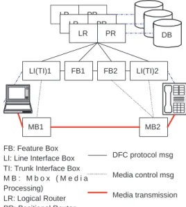
LR PR DB LR PR DB FB1 LI(TI)1 FB2 LI(TI)2 MB1 MB2 FB: Feature Box LI: Line Interface Box TI: Trunk Interface Box M B : M b o x ( M e d i a Processing) LR: Logical Router PR: Positional Router DB: Database DFC protocol msg Media control msg Media transmission Other msg LR PR DB Router B A Router CW 1 2 4 3 6 7 8 10 5 9
(1) setup (2) setup (3) setup (4) upack (5) connected (6) setup (7) setup (8) upack (9) connected
(10) media open (11) setup (12) setup (13) upack (14) connected (15) setup (16) status (switch) (17) media open
C 11 12 13 15 14 16 17 (a) (b)
Figure 4: Distributed Feature Composition (DFC) architecture (a) and call waiting implementation (b)
DFC treats features as independent components, called feature boxes (FB). A call is routed through these feature boxes. The features are applied during the routing. The DFC architecture has four main components: the feature boxes (FB), media processing boxes (MB) which are responsible for switching, replicating and summing media streams2, line interface (LI) box and trunk interface (TI) boxes that sit between a DFC network and other end systems or networks, and finally routers which direct call signaling messages.
Calls are routed to feature boxes in two phases, logical and positional, which are carried out by the logical routers (LR) and positional routers (PR), respectively. The logical router decides which feature boxes will be applied to the call and the positional router decides the order of the feature boxes. The routing decision is based on subscription, precedence, dialing predicate and configuration data. In a DFC network, the call between feature boxes are featureless signals, i.e., the content of the signaling message does not depend on the feature boxes the signal connects. To install a new feature, the LR and PR boxes have to be appropriately configured by the carrier. The scope of DFC is one network. One DFC network can be connected to the other network through trunk interface. Two LR/PR can talk to each other through Provisioning Manager. The LR/PR can register its information to Provisioning Manager. Provisioning Manager uses the same hierachical architecture as DNS to provide scalability.
Figure 4 (b) shows how call waiting service is handled in DFC. (“upack” is the acknowledgment message for the setup message, while “flash” refers to the end system signaling a hook flash.) In this figure, if we replace the CW box with another feature box or add some more feature boxes, the call set up will follow the same path. The DFC approach decomposes complex behavior into simpler features, instead of handling them in a monolithic program. Abstracted, the main difference to the programming model above is that the order of feature execute is based on the interaction between LR/PR and the feature boxes, rather than “hop-by-hop” as in the programming model described earlier.
3.2
Comparison of service creation mechanisms
Comparing Fig. 1 and 4 (b), 3 (a) and (b), we notice that the approach in the end system requires the smaller number of messages and is less complicated for providing the service. It also offers full call information to the user. Since these services do not require access to persistent memory or other external resources, this model is probably appropriate.
Using programmable service logic, Fig. 3 (a), the service logic is contained in a separate script can can thus be implemented by a third party. The server only needs to know which script to invoke when receiving a call.
DFC, Fig. 4 (b), provides CW in a separate feature box, rather than as part of a per-user script. Since feature boxes are independent to each other, each service can be implemented by a third party. The modularity also makes it
easy to reuse the existing service implementations. Feature boxes could use CPL internally. Compared with having a single script per user, DFC limits feature interaction to a strict sequence. Features cannot be invoked conditionally, depending on the outcome of invoking previous features. DFC could also be used inside the service logic part of Fig. 3 (a), rather than be spread across multiple servers.
4
Feature interaction between end systems and the network
Since traditional telecommunication networks assume dumb terminals, there are rarely service interactions between end system and network services. However, in an Internet telephony system, especially when interoperating with the legacy telephone system, such kind of service interactions are more likely.
One example of this interaction is when features are implemented in one or more servers as well as an end system. Calls may never reach the end system, having been rejected or deflected earlier in their path. It may become hard to track which service is installed where, and to keep their behavior or implementation synchronized [14].
5
Conclusion
Powerful end systems offer benefits such as flexibility and personalized services, but introduce new challenges. What kind of services should be implemented in end systems and what kind of services can only be implemented in the network? What mechanisms are good for service creation in end systems and in the network? How can one deal with the interaction between services implemented in various parts of the network?
We have investigated these problems and compared three mechanisms for service creation, namely end system implementation, server implementation in a gateway or proxy and the DFC architecture. End system implementations are simplest, but not suitable for many services. DFC and SIP proxy implementations make it possible to split services across several servers, with differing approaches on how to route the signaling messages between such servers. The interaction between end system services and network services is still an open issue.
References
[1] J. Rosenberg, J. Lennox, and H. Schulzrinne, “Programming internet telephony services,” IEEE Network, vol. 13, pp. 42–49, May/June 1999. [2] J. Lennox and H. Schulzrinne, “Call processing language framework and requirements,” Request for Comments 2824, Internet Engineering
Task Force, May 2000.
[3] J. Lennox, J. Rosenberg, and H. Schulzrinne, “Common gateway interface for SIP,” Internet Draft, Internet Engineering Task Force, May 1999. Work in progress.
[4] C. Huitema, J. Cameron, P. Mouchtaris, and D. Smyk, “An architecture for internet telephony service for residential customers,” IEEE Network, vol. 13, pp. 50–57, May/June 1999.
[5] M. Jackson and P. Zave, “Distributed feature composition: A virtual architecture for telecommunications services,” IEEE Transactions on Software Engineering, Aug. 1998.
[6] P. Zave and M. Jackson, “DFC modifications II: Protocol extensions,” tech. rep., AT&T Research Lab, Nov. 1999. At http://www.research.att.com/ pamela/x2.ps.
[7] P. Zave and M. Jackson, “DFC modifications III: Signalling/media separation,” tech. rep., AT&T Research Lab, Dec. 1999. At http://www.research.att.com/ pamela/x3.ps.
[8] P. Zave and M. Jackson, “DFC modifications I (version 2): Routing extensions,” tech. rep., AT&T Research Lab, 2000. At http://www.research.att.com/˜pamela/x1.ps.
[9] M. Handley, H. Schulzrinne, E. Schooler, and J. Rosenberg, “SIP: session initiation protocol,” Request for Comments 2543, Internet Engi-neering Task Force, Mar. 1999.
[10] AT&T, 5ESS Switch, The Premier Solution: Feature Handbook. AT&T, 4 ed., Sept. 1987.
[11] M. Handley, J. Crowcroft, C. Bormann, and J. Ott, “The internet multimedia conferencing architecture,” Internet Draft, Internet Engineering Task Force, July 1997. Work in progress.
[12] A. Kristensen and A. Byttner, “The SIP servlet API,” Internet Draft, Internet Engineering Task Force, Sept. 1999. Work in progress. [13] J. Lennox and H. Schulzrinne, “Transporting user control information in SIP REGISTER payloads,” Internet Draft, Internet Engineering Task
Force, Mar. 1999. Work in progress.
[14] J. Lennox and H. Schulzrinne, “Feature interaction in internet telephony,” in Proc. of Feature Interaction in Telecommunications and Software Systems VI, (Glasgow, United Kingdom), May 2000.