LINKS
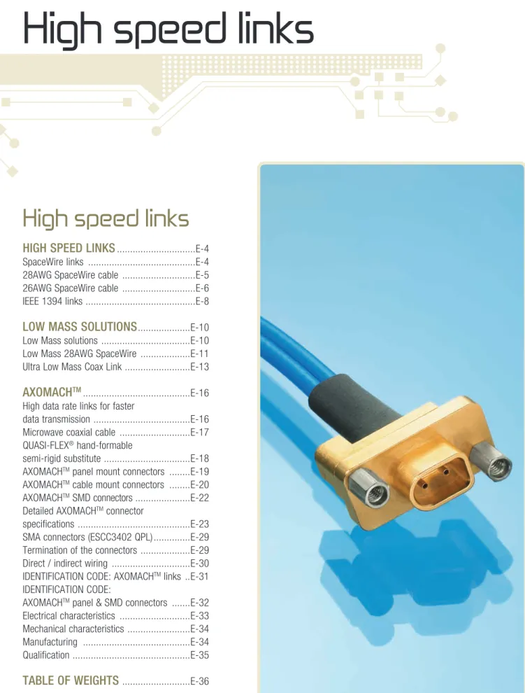
High speed links
High speed links
HIGH SPEED LINKS
...E-4 SpaceWire links ...E-4 28AWG SpaceWire cable ...E-5 26AWG SpaceWire cable ...E-6 IEEE 1394 links ...E-8LOW MASS SOLUTIONS
...E-10 Low Mass solutions ...E-10 Low Mass 28AWG SpaceWire ...E-11 Ultra Low Mass Coax Link ...E-13AXOMACH
TM ...E-16 High data rate links for fasterdata transmission ...E-16 Microwave coaxial cable ...E-17 QUASI-fLEx® hand-formable
semi-rigid substitute ...E-18 AxOMACHTM panel mount connectors ...E-19
AxOMACHTM cable mount connectors ...E-20
AxOMACHTM SMD connectors ...E-22
Detailed AxOMACHTM connector
specifications ...E-23 SMA connectors (ESCC3402 QPL) ...E-29 Termination of the connectors ...E-29 Direct / indirect wiring ...E-30 IDENTIfICATION CODE: AxOMACHTM links ..E-31
IDENTIfICATION CODE:
AxOMACHTM panel & SMD connectors ...E-32
Electrical characteristics ...E-33 Mechanical characteristics ...E-34 Manufacturing ...E-34 Qualification ...E-35
SpaceWire links
"LVDS spacecraft communication network" to ESCC-E-50-12C
AxON’ has developed cables and connectors for SpaceWire links, allowing transfer speeds up to 400 Mb/s.
AxON' SpaceWire has been approved to ESCC-E-50-12C (SpaceWire cabling) by the french National Space Engineering Centre (CNES).
Signal integrity
AxON' digital data transmission bus assemblies which meet the MIL-STD-1553 standard are used for military and aeronautic applications, and have also been integrated within the space environment for over 10 years.
In addition to bus harnesses which ensure the connection between on-board devices, SpaceWire links make possible the transfer of up to 400Mb/s while maintaining a wide working margin, thanks to the use of CELLOfLON®, expanded PTfE developed by AxON'. The ESCC 3902/003 qualified cable and ESCC 3401/029 EPPL2 connectors and accessories manufactured by AxON' protect the integrity of LVDS signals (Low Voltage Differential Signalling) provided by the devices. The cabling has been optimised in order to reduce the mismatching and crosstalk between lines at the maximum.
A test report validates every SpaceWire link. The electrical performance, which depends on the transmission speed, can be shown with an eye pattern which includes characteristics such as signal jitter. AxON' can analyse high speed signals up to 10 Gb/s.
Engineering Model or Flight Model designs
AxON’ can offer several designs for Engineering Models (EM) or flight Models (fM) on request. for custom Lab test harness, AxON’ can offer lightweight design configurations for a more cost effective solution (EMI backshell replaced by conductive potting).
Electrical & environmental characteristics
RADIATION 20 Mrad (for static use) Jitter (@ 400 Mb/s) < 0.35 nS Skew (data and strobe lines
at 400 Mb/s, length 5 m max.) < 0.5 nS
SPACEWIRE LINKS
E-4
E-5
LINKS28AWG SpaceWire cable
CONSTRUCTIONAxON’ 28AWG SpaceWire cable qualified to ESCC 3902/003 variant 01 (AxON’ part number: P532242) consists of 4 shielded twisted pairs covered by an overall shield and outer jacket, as shown in the specification.
1 - CELLOFLON® expanded PTFE filler - Diameter: 1.00 mm nom.
2 - 4 x 100 Ω 28AWG BUS Lines
CONDUCTOR AWG 2807
- Stranded silver plated copper alloy 2 µm. - 7 x 0.127 mm strands.
- Diameter: 0.38 mm nominal. - Cross section: 0.089 mm2 nominal. - Resistance: 23 Ω/100 m nominal. DIELECTRIC: CELLOfLON® expanded PTfE. - Colour: blue / white.
BRAIDED SHIELD
- Material: silver plated copper 2.5 µm. - Strand diameter: 0.079 mm. JACKET
- Material: extruded PfA. - Diameter: 2.37 mm nominal. - Colour: white.
3 - CELLOFLON® expanded PTFE tape
4 - Braided shield
- Material: silver plated copper 2.5 µm. - Strand diameter: 0.102 mm.
5 - Outer jacket
- Material: PfA. - Colour: white.
MAIN CHARACTERISTICS
- Outer diameter: 7.5 mm maximum. - Weight: 85 g/m maximum.
- Operating temperature: -200 / +180°C.
- Impedance (between wires): 100 Ω (±6 Ω) at 400 MHz.
SPACEWIRE LINK WITH EMI BACKSHELL 2
3 1
4
E-6
HIGH SPEEDLINKS26AWG SpaceWire cable
CONSTRUCTIONAxON’ 26AWG SpaceWire cable qualified to ESCC 3902/003 variant 02 (AxON’ part number: P544806) consists of 4 shielded twisted pairs covered by an overall shield and outer jacket, as shown in the specification.
1 - CELLOFLON® expanded PTFE filler - Diameter: 1.40 mm nominal.
2 - 4 x 100 Ω 26AWG BUS Lines
CONDUCTOR AWG 2607
- Stranded silver plated copper alloy 2 µm. - 7 x 0.160 mm strands.
- Diameter: 0.48 mm nominal. - Cross section: 0.141 mm2 nominal. - Resistance: 14 Ω/100 m nominal. DIELECTRIC: CELLOfLON® expanded PTfE. - Colour: blue / white.
BINDER BRAIDED SHIELD
- Material: silver plated copper 2.5 µm. - Strand diameter: 0.079 mm. JACKET
- Material: extruded PfA. - Diameter: 3.05 mm nominal. - Colour: white.
3 - CELLOFLON® expanded PTFE tape
4 - Braided shield
- Material: silver plated copper 2.5 µm. - Strand diameter: 0.102 mm.
5 - Outer jacket
- Material: PfA. - Colour: blue
MAIN CHARACTERISTICS
- Outer diameter: 9.00 mm maximum. - Weight: 115 g/m maximum.
- Operating temperature: -200 / +180°C.
- Impedance (between wires): 100 Ω (±6 Ω) at 400 MHz.
SPACEWIRE CABLE 2 3 1 4 5
E-7
LINKS26AWG SpaceWire cable
Test and measurements
• Eye pattern measurements (up to 10 Gb/s), - Jitter measurements,
- Eye height and width, - Q factor,
- Skew.
• TDR (Time Domain Reflectometry) analysis, - Impedance analysis,
- Skew. • BER test (Bit Error Rate),
- PRBS (Pseudo Random Binary Sequence) generation and analysis.
Connection
for either cable size (AWG26 or AWG28), there are two possibilities to connect the link to the PCB:
- Pigtail whose wires are soldered to the PCB.
- Special 9 way CBR connector (each line has the same electrical length to reduce the skew between one another).
SPACEWIRE LINKS
WIRING DIAGRAM (ACCORDING TO ECSS-E-50-12C)
White Blue White Blue White Blue Blue White EYE PATTERN - 400 MBPS 9 WAY CBR CONNECTOR
E-8
HIGH SPEEDLINKSIEEE 1394 links
IEEE 1394 A used as spacecraft communication network.
CONSTRUCTION
AxON’ IEEE 1394 cable (AxON’ part number: P838566) consists of two screened twisted pairs and one unscreened twisted pair as shown in the specification. The cable has an overall shield and jacket.
1 - One 26AWG unscreened pair
CONDUCTOR AWG 2619
- Stranded silver plated copper alloy 2 µm. - 19 x 0.102 mm strands.
- Diameter: 0.504 mm nominal. - Cross section: 0.15 mm2 nominal. - Resistance: 13.65 Ω/100 m nominal. DIELECTRIC: Extruded PTfE.
- Colour: black / white. - Diameter: 1.00 mm nominal.
2 - Two screened pairs CRP 26AWG - 110 Ω
CONDUCTOR AWG 2619
- Stranded silver plated copper alloy 2 µm. - 19 x 0.102 mm strands.
- Diameter: 0.504 mm nominal. - Cross section: 0.15 mm2 nominal. - Resistance: 13.65 Ω/100m nominal. DIELECTRIC: CELLOfLON® (expanded PTfE). - Colour: red-green & orange-blue. BRAIDED SHIELD
- Material: silver plated copper 2 µm minimum. - Strand diameter: 0.079 mm.
- Diameter: 2.95 mm nominal.
3 - Drain wire: AWG2619
CONDUCTOR: same as above.
4 - CELLOFLON® expanded PTFE filler
5 - Two bonded polymide separating tapes 6 - Braided shield
- Material: silver plated copper 2.5 µm. - Strand diameter: 0.127 mm.
7 - Outer jacket
- Material: wrapped PTfE. - Colour: white
MAIN CHARACTERISTICS
- Outer Diameter: 7.15 mm maximum. - Weight: 84 g/m maximum.
- Operating temperature: -90°C / +200°C. - Impedance (pair CRP2619 S2): 110 Ω (±6 Ω). - Voltage rating (E2619): 600 VAC.
IEEE 1394 CABLE IEEE 1394 LINK 2 3 1 4 5 6 7
E-9
LINKSIEEE 1394 links
Test and measurements
• Eye pattern measurements (up to 10 Gb/s), - Jitter measurements,
- Eye height and width, - Q factor,
- Skew.
• TDR (Time Domain Reflectometry) analysis, - Impedance analysis,
- Skew. • BER test (Bit Error Rate),
- PRBS (Pseudo Random Binary Sequence) generation and analysis.
Connection
There are two possibilities to connect the link to the PCB: - Pigtail whose wires are soldered to the PCB.
- Special 9 way CBR connector (each line has the same electrical length to reduce the skew between one another).
IEEE 1394 LINK P1 P2 White Black Red Green Blue Orange WIRING DIAGRAM
Inner shields are in contact with each other and insulated from the outer shield.
Low Mass solutions
E-10
Low Mass solutions
> AxON's Low Mass SpaceWire has been submitted to an extensive evaluation under ESA supervision, and is curently pending ESA qualification. It is approximately half the mass of existing SpaceWire.
> The Ultra Low Mass Coax Link, based on AxON's coaxial cable expertise, is almost 30% lighter still, and is significantly smaller and even more flexible. It is not ESA endorsed for the SpaceWire protocol, but may still be interesting for certain applications.
Main characteristics
SpaceWire ESCC 3902.003.01 Low Mass SpaceWire ESCC 3902.004.01 Ultra Low Mass Coax Link with overall shieldUltra Low Mass Coax
Link without overall
shield Mass (g/m) 80 max. 42 max. 32.5 max. 30 max. Overall Ø (mm) 7 max. 6.5 max. 4.5 max. 4.2 max.
Static bend radius 45 25 10 6
Dynamic bend radius 60 30 20 15 Impedance (Ω) 100 ±6 100 ±6 2x50 ±2 2x50 ±2 Capacitance (pf) - intra pair - inter pair < 50< 90 < 50< 90 < 48< 97 < 48< 97 Resistance DC (Ω/m) 0.23 0.23 0.90 0.90
Intra pair skew
(ps/m) < 80 < 50 < 20 < 20
Inter pair skew
(ps/m) < 130 < 100 < 20 < 20
α (dB/m) @1 GHz Cable length (for -6 dB atten.)
-1.5
4.5 m max.* 4.6 m max.*-1.4 2.3 m max.*-2.6 2.3 m max.*-2.6 Return Loss (dB)
up to 2 GHz -9 max. -9 max. -20 max. -20 max.
*= for a 400 Mb/s data rate (1 GHz)
With long experience
in space wiring and
a mastery of many
advanced cabling
technologies, AXON'
has designed two
new solutions to
lighten traditional
high speed links:
The Low Mass
SpaceWire and
the Ultra Low
Mass Coax Link.
E-11
LINKSLow Mass 28AWG SpaceWire
Making use of AxON's CELLOfLON® expanded PTfE, alveolar a-PTfE dielectrics and AxON's patented AxALU® silver plated aluminium shields, the new Low Mass SpaceWire cable saves almost half the weight compared to conventional SpaceWire.
CONSTRUCTION
AxON’s Low Mass 28AWG SpaceWire cable according to the ESCC 3902/004.01
requirements (AxON’ part number: P551259) consists of 4 shielded twisted pairs covered by an overall shield and outer jacket, as shown in the specification.
1 - CELLOFLON® expanded PTFE filler - Diameter: 1.35 mm nom.
2 - 4 x 100 Ω 28AWG BUS Lines
CONDUCTOR AWG 2819
- Stranded silver plated copper alloy (2 µm minimum). - 19 x 0.079 mm strands.
- Diameter: 0.395 mm nominal. - Cross section: 0.093 mm2 nominal. - Resistance: 23 Ω/100 m nominal. DIELECTRIC: Alveolar PTfE. - Colour: blue / white. INNER BRAIDED SHIELD
- Material: silver plated aluminium (2 µm minimum). - Strand diameter: 0.079 mm.
3 - Braided shield (in electrical contact with the inner braided shields) - Material: silver plated aluminium (2 µm minimum).
- Strand diameter: 0.100 mm.
4 - Outer jacket
- Material: Expanded PTfE tape (CELLOfLON®) under a Polyimide tape.
MAIN CHARACTERISTICS
- Outer diameter: 6.5 mm maximum.
- Bend radius: 25 mm minimum for fully static applications. - Weight: 42 g/m maximum.
- Operating temperature: -100 / +150°C.
- Impedance (between wires of a pair): 100 Ω (±6 Ω) at 400 MHz. - All inner shields are in contact with overall shield.
MAIN ADVANTAGES COMPARED TO THE ESCC3902/003 VARIANT 01
- Smaller bend radius (routing made easier) - Approximately half the weight
- Reduced intra-pair and inter-pair skews
- Improved resistance to radiations (evaluation performed up to 300 Mrad) 2
1
3
E-12
HIGH SPEEDLINKSPart list
1 - Low Mass SpaceWire cable (P551259)
2 - Micro-D plug connector (MDSA209P000B: 9 ways / high phosphorous nickel plated) 3 - High phosphorous nickel plated backshell and stainless steel 2-56 UNC-2A fastners 4 - Marking sleeve
ESCC 3902.003/01 3902.004/01
PART NUMBER P532242 P551259
WEIGHT 85 g/m 42 g/m
DIAMETER 7 mm max. 6.5 mm max.
Cable shield connection: All shields are terminated to the shell of the Micro-D connectors. Alternatively, the shields can also be connected to pin 3 at both ends on request.
Skew inter pair: 0.1 ns/m maximum. / Skew intra pair: 0.05 ns/m maximum.
Depending on the required frequency and data rate, this assembly can be up to 10 meters long without exceeding the 6 dB attenuation limit. This limit is measured at the 5th harmonic of the fundamental equivalent frequency of the LVDS signal (250MHz for 100Mb/s; 500MHz for 200Mb/s or 1GHz for 400Mb/s). The real requirement is to be outside the mask (see above). Please contact us for more details.
Test and measurements
- Eye pattern measurements (up to 10 Gb/s): Jitter measurements, Eye height and
width, Q factor and Skew.
- TDR (Time Domain Reflectometry) analysis: Impedance analysis and Skew.
- BER test (Bit Error Rate): PRBS (Pseudo Random Binary Sequence) generation and
analysis.
- Crosstalk
connector 1 connector 2
WIRING DIAGRAM (PINS ALLOCATION) White Blue White Blue White Blue Blue White connector 1 connector 2
EYE PATTERN DIAGRAM MEASUREMENT AT 400 Mb/s fOR EACH PAIR Of A LIGHTWEIGHT SPACEWIRE ON A 4.5 m ASSEMBLY. WORST CASE Of AMPLITUDE (250 mV peak).
SPACEWIRE PERfORMANCES MASK fOR EYE PATTERN MEASUREMENT.
EYE PATTERN MODEL GIVEN fOR THE NExT ISSUE Of THE ECSS-E-ST-50-12 STANDARD. THE SIGNALS fROM THE CABLE ASSEMBLY SHALL REMAIN OUTSIDE THE MASK AT RECEIVER END.
E-13
LINKSUltra Low Mass Coax Link
The Ultra Low Mass Coax Link based on AxON' coaxial cable expertise, is almost 30%
lighter than the already very light Low Mass SpaceWire. This radical solution is significantly smaller and more flexible than the conventional twisted pair approach and exceeds the performance requirements for high speed serial data links compared to twisted pair cables. The coaxial based cable is not recommended for ECSS-E-ST-50-12C SpaceWire links. It can therefore be an interesting alternative for applications where installation space and mass budgets are extremely limited, or particularly where an alternative protocol to SpaceWire is in use.
Important: Potential users of this solution must ensure for themselves that the cable is
compatible with their application.
CONSTRUCTION
AxON’s Ultra Low Mass Coax Link (AxON’ part numbers: P551260 for the version without overall shield and P547585 for version with) consists of 8 coaxial cables stranded around a filler and outer tape, as shown in the specification.
1 - CELLOFLON® expanded PTFE filler - Diameter: 1.70 mm nominal.
2 - 8 x 50 Ω SM50 Coaxial cables
CONDUCTOR AWG 3407
- Stranded silver plated copper alloy (2 µm). - 7 x 0.063 mm strands.
- Diameter: 0.187 mm nominal. - Cross section: 0.020 mm2 nominal. - Resistance: 90.9 Ω/100 m nominal. DIELECTRIC: PTfE
- Colour: white. BRAIDED SHIELD
- Material: silver plated copper (2.5 µm). - Strand diameter: 0.063 mm.
JACKET
- Material: extruded PfA. - Colour: white.
3 - CELLOFLON® expanded PTFE tape (on P551260 only)
4 - Braided shield (on P547585 only)
5 - Polyimide tape (single layer on P551260, double layer on P547585)
MAIN CHARACTERISTICS
- Outer diameter: 4.20 mm maximum (4.50 mm with overshield). - Bend radius: 6 mm minimum for fully static applications. - Weight: 30 g/m maximum (32.5 g/m with overshield). - Operating temperature: -100 / +150°C.
- Impedance (between wires of a pair): 8x50 Ω at 400 MHz.
MAIN ADVANTAGES COMPARED TO THE ESCC 3902/003 VARIANT 01
- Smaller bend radius (routing made easier) - More than half weight saving
- Reduced intra-pair and inter-pair skews - Improved resistance to radiations
Note: One drawback is a shorter maximum length due to higher attenuation.
Ultra Low Mass Coax Links can be terminated with 9 way Micro-D connectors (such as are employed on SpaceWire and Low Mass SpaceWire links) or ultra miniature 15 way Nano-D connectors, suitable for applications where the connector interface area is extremely limited. 2
3 1
5
ULTRA LOW MASS COAx LINK
P551260 2 1 5 P547585 4
E-14
HIGH SPEEDLINKSPart list
1 - Ultra Low Mass Coax cable (P551260 or P547585)
2 - Micro-D plug connector (MDSA209P000B: 9 ways / high phosphorous nickel plated) 3 - High phosphorous nickel plated backshell and stainless steel 2-56 UNC-2A fastners 4 - Marking sleeves
ESCC 3902.003/01 Ultra Low Mass Coax cable
with overall shield
Ultra Low Mass Coax cable without overall shield
PART NUMBER P532242 P547585 P551260
WEIGHT 85 g/m 32.5 g/m 30 g/m
DIAMETER 7 mm max. 4.5 mm max. 4.2 mm max.
Cable shield connection: All coaxial shields are terminated to the shell of both connectors.
Skew inter pair: 0.1 ns/m maximum. / Skew intra pair: 0.02 ns/m maximum.
Depending on the required frequency and data rate, this assembly can be up to 4 meters long without exceeding the 6 dB attenuation limit. This limit is measured at the 5th harmonic of the fundamental equivalent frequency of the LVDS signal (250MHz for 100Mb/s; 500MHz for 200Mb/s or 1GHz for 400Mb/s). The real requirement is to be outside the mask (see above). Please contact us for more details.
Test and measurements
- Eye pattern measurements (up to 10 Gb/s): Jitter measurements, Eye height and
width, Q factor and Skew.
- TDR (Time Domain Reflectometry) analysis: Impedance analysis and Skew.
- BER test (Bit Error Rate): PRBS (Pseudo Random Binary Sequence) generation and
analysis.
- Crosstalk
WIRING DIAGRAM (PINS ALLOCATION)
connector 1 connector 2
connector 1 connector 2
SPACEWIRE PERfORMANCES MASK fOR EYE PATTERN MEASUREMENT.
EYE PATTERN MODEL GIVEN fOR THE NExT ISSUE Of THE ECSS-E-ST-50-12 STANDARD. THE SIGNALS fROM THE CABLE ASSEMBLY SHALL REMAIN OUTSIDE THE MASK AT RECEIVER END.
E-15
LINKSPart list
1 - Ultra Low Mass Coax cable (P551260 or P547585)
2 - Nano-D plug connector (ND2A215P000B: 15 ways / nickel plated) 3 - Nickel plated backshell and stainless steel 0-80 UNf fasteners 4 - Marking sleeves
ESCC 3902.003/01 Ultra Low Mass Coax cable
with overall shield
Ultra Low Mass Coax cable without overall shield
PART NUMBER P532242 P547585 P551260
WEIGHT 85 g/m 32.5 g/m 30 g/m
DIAMETER 7 mm max. 4.5 mm max. 4.2 mm max.
Cable shield connection: All coaxial shields are terminated to the shell of both connectors.
Skew inter pair: 0.1 ns/m maximum. / Skew intra pair: 0.02 ns/m maximum.
Depending on the required frequency and data rate, this assembly can be up to 4 meters long without exceeding the 6 dB attenuation limit. Please contact us for more details.
Test and measurements
- Eye pattern measurements (up to 10 Gb/s): Jitter measurements, Eye height and
width, Q factor and Skew.
- TDR (Time Domain Reflectometry) analysis: Impedance analysis and Skew.
- BER test (Bit Error Rate): PRBS (Pseudo Random Binary Sequence) generation and
analysis.
- Crosstalk
connector 1 connector 2
WIRING DIAGRAM (PINS ALLOCATION)
High data rate links
for faster data transmission
AxON’ proposes AxOMACHTM, a range of high data rate links composed of low loss microwave coaxial cables and different connector types: AxOMACHTM Micro-D based cable mount, panel mount, SMD or saver connectors as well as SMA panel mount connectors. Aimed, for example, at the interconnection of high definition imagery sensors in satellites these links present the following main advantages:
- Transmission of high data rates: 10 Gb/s up to 40 Gb/s, - Signal integrity: skew < 10 ps per mated pair,
- Low mismatching: differential characteristic impedance 100 Ω (±10 Ω), - Low crosstalk < -35 dB at 10 GHz,
- Improved EMC behavior: shielding effectiveness for 1 m link < -60 dB up to 10 GHz, - Space saving: about half the width of a standard SMA connector for the same
number of contacts. Construction
A procurement specification is available on request. This document following ESCC format details the rating, physical and electrical characteristics, test & inspection data for AXON' space grade high data rate AXOMACHTM series connectors and links.
On the following pages each component of this high data rate link will be described in detail.
CABLE MOUNT fEMALE AxOMACHTM CONNECTOR
E-16
AXOMACH
TM
Panel mount connector
Cable mount connector 1 Microwave coaxial cables QUASI-fLEx® Cable mount connector 2 SMD connector
E-17
LINKSMicrowave coaxial cable
AXOWAVETM 2.4
AxON’ part number: P840563
Cable terminated with Micro-D based cable mount connectors, PCB connectors, SMA connectors.
CONDUCTOR
- Silver plated copper (Ag 2µm). - AWG 2401.
- Area 0.205 mm². - Resistance: 10 Ω/100 m.
DIELECTRIC
- Extruded CELLOfLON® (expanded PTfE). - Colour: natural.
- Nominal diameter: 1.51 mm.
SHIELDING
Silver plated copper tape.
SEPARATING TAPE
Polyimide.
SHIELDING
Silver plated copper braid (Ag 2µm), nominal diameter over braid: 1.92 mm.
JACKET
- PfA. - Colour: blue.
MAIN CHARACTERISTICS
- Nominal outer diameter: 2.40 mm. - Approximate weight: 16 g/m. - Nominal impedance: 50 Ω. - Nominal capacitance: 87 pf/m. - Temperature rating: -65°C to +150°C. - Maximum attenuation: • 0.70 dB/m at 1 GHz. • 1.55 dB/m at 5 GHz. • 2.20 dB/m at 10 GHz. • 3.05 dB/m at 18 GHz. - Velocity of propagation: > 76%.
E-18
HIGH SPEEDLINKSQUASI-FLEX®
hand-formable
semi-rigid substitute
QFX086S
AxON’ part number: P540264
Cable connected to a PCB connector on one side and welded to the equipment PCB on the other side.
CONDUCTOR
- Solid conductor.
- Silver plated copper clad steel (Ag 2µm). - Nominal diameter: 0.51 mm.
DIELECTRIC
- Extruded PTfE.
- Nominal diameter: 1.65 mm.
SHIELDING
Tin soaked silver plated copper braid (space quality defined by ECSS-Q-10-71 A).
MAIN CHARACTERISTICS
- Nominal outer diameter: 2.15 mm. - Approximate weight: 17 g/m. - Impedance: 50 Ω (± 2 Ω). - Nominal capacitance: 97 pf/m. - Temperature rating: -55°C to +125°C. - Maximum attenuation: • 0.70 dB/m at 1 GHz. • 1.30 dB/m at 3 GHz. • 1.85 dB/m at 6 GHz. • 2.45 dB/m at 10 GHz. • 3.55 dB/m at 18 GHz. - Velocity of propagation: > 69%.
E-19
LINKSQUASI-FLEX®
hand-formable
semi-rigid substitute
AXOMACH
TM
panel mount connectors
Materials: Mechanical:
- Body: 2.5 µm gold on aluminium alloy - Torque screw-nut: 0.35 N.m - Dielectric: PTfE - Nut thickness: 1.6 mm
- Rear contact: 1.2 µm gold on copper alloy - Washer dimensions (e x D): 0.3 x Ø4.7 mm - Mated contact: 1.2 µm gold on copper alloy - Nuts and washers are included
Single way female panel mount connector VARIANT 01 (see details page E-23)
Two way female panel mount connector VARIANT 02 (see details page E-23)
Four way female panel mount connector VARIANT 03 (see details page E-24)
E-20
HIGH SPEEDLINKSAXOMACH
TM
cable mount connectors
- Special 100 Ω insert for the transmission line- Interfacial seal / connector to backshell interface seals: conductive silicone base rubber - Shrinkable strain relief: fluoropolymer
Materials:
- Body: 2.5 µm gold on aluminium alloy - Dielectric: PTfE
- Pin contact: 1.2 µm gold on copper alloy
Single way male cable mount connector VARIANT 04 (see details page E-24)
Two way male cable mount connector
VARIANT 05 (see details page E-25)
Four way male cable mount connector
E-21
LINKSSingle way female cable mount connector VARIANT 07 (see details page E-26)
Two way female cable mount connector VARIANT 08 (see details page E-26)
Four way female cable mount connector VARIANT 09 (see details page E-27)
E-22
HIGH SPEEDLINKSAXOMACH
TM
SMD connectors
Materials:- Body: 2.5 µm gold on aluminium alloy - Dielectric: PTfE
- Mated contact: 1.2 µm gold on copper alloy
Single way female SMD connector
VARIANT 10 (see details page E-27)
Two way female SMD connector
VARIANT 11 (see details page E-28)
Four way female SMD connector
E-23
LINKSDetailed AXOMACH
TM
connector
specifications
Single way female panel mount connector VARIANT 01
Two way female panel mount connector VARIANT 02
E-24
HIGH SPEEDLINKSFour way female panel mount connector VARIANT 03
Single way male cable mount connector VARIANT 04
E-25
LINKSTwo way male cable mount connector VARIANT 05
Four way male cable mount connector VARIANT 06
E-26
HIGH SPEEDLINKSSingle way female cable mount connector VARIANT 07
Two way female cable mount connector VARIANT 08
E-27
LINKSFour way female cable mount connector VARIANT 09
Single way female SMD connector VARIANT 10 19mm Socket 1 Socket 2 9mm 23mm 10 .7 m m Threaded hole 2-56 UNC - 2B
Recommended tightening torque: 30cNm 0/+10% 1.55mm 11.5mm 7.5mm 8. 7m m 1.8mm MIN 2.5mm 21.3mm 25.74mm Coax Cable 2 Coax Cable 1 Jackpost 2-56 UNC - 2B
E-28
HIGH SPEEDLINKSTwo way female SMD connector VARIANT 11
Four way female SMD connector VARIANT 12 28mm Socket 1 Socket 2 Socket 3 Socket 4 9m m 32mm 10 .7 m m Threaded hole 2-56 UNC - 2B
Recommended tightening torque: 30cNm 0/+10% 6.55mm 3.45mm 16mm 12mm 8. 7m m 1.8mm MIN 2.5mm 25.74mm 21.3mm Coax Cable 4 Coax Cable 3Coax Cable 2
Coax Cable 1 Jackpost 2-56 UNC - 2B Socket 1 Socket 2 Socket 3 Socket 4 Socket 5 Socket 6 Socket 7 Socket 8 9m m 52mm 10 .7 m m Threaded hole 2-56 UNC - 2B
Recommended tightening torque: 30cNm 0/+10% 16.55mm 13.45mm 3.45mm 6.55mm 26mm 22mm 8. 7m m
Coax Cable 8Coax Cable 7 Coax Cable 6 Coax Cable 5 Coax Cable 4 Coax Cable 3Coax Cable 2
Coax Cable 1 Jackpost 2-56 UNC - 2B 21.3mm 25.74mm 1.8mm MIN 48mm
E-29
LINKSSMA connectors (ESCC3402 QPL)
To connect AxOMACHTM links to your devices equipped with SMA plugs or to create panel feedthroughs, AxON’ proposes the following ESA qualified SMA connectors:
ESCC VARIANT TECHNICAL CONFIGURATION
ESCC3402/001 variant 01 Straight plug, solder type, for semi-rigid cable Ø 2.2 mm. ESCC3402/001 variant 09 Right angle plug, solder type, for semi-rigid cable Ø 2.2 mm. ESCC3402/002 variant 01 Straight jack, solder type, for semi-rigid cable Ø 2.2 mm. ESCC3402/002 variant 09 Straight jack, solder type, rear mounting, 2 holes, flange mounted, for semi-rigid cable Ø 2.2 mm. ESCC3402/002 variant 68 Straight jack, solder type, rear mounting, flange mounted, for
semi-rigid cable Ø 2.2 mm.
ESCC3402/003 variant 07 Hermetic adaptor, female-female. ESCC3402/003 variant 14 Straight bulkhead adaptor, female-female.
This list is non exhaustive.
AxOMACHTM SMD CONNECTOR AxOMACHTM CABLE MOUNT CONNECTOR
Termination of the connectors
AXOMACHTM panel mount connectors (variants 01 to 03)
This connector can be terminated to a PCB using flat flexible conductors in order to be mechanically decoupled between the PCB and the panel where the connector is mounted. One end of the flat conductor is soldered to the connector lead using high temperature solder or a parallel gap weld procedure. The other end is soldered on PCB tracks by using standard soldering.
This termination must be validated and approved depending on the mission environment.
AXOMACHTM cable mount connectors (variants 04 to 09) and surface mount
connectors (variants 10 to 12)
- Inner conductor is crimped to gold plated copper alloy contacts. - Cable shield is soldered into the backshell using soft soldering. - x-Ray inspection is performed on all link terminations.
Transmission measurements are performed on 100% of manufactured links up to 10 Gb/s. The manufacturing and control procedures are maintained in a PID followed by CNES/ESA and reviewed every two years.
AxOMACHTM PANEL CONNECTOR
E-30
HIGH SPEEDLINKSDirect / indirect wiring
There are two ways to wire AxON's AxOMACHTM links: direct wiring and indirect wiring. Direct wiring being the standard way, indirect wiring is used to meet customers' specific requirements.
The type of wiring appears in the identification code of AxOMACHTM links. AXOMACH 05D300 05 L3 = Direct wiring
AXOMACH 05I300 05 L3 = Indirect wiring
Direct wiring Indirect wiring 1 2 3 4 5 6 7 8 1 2 3 4 5 6 7 8 1 2 3 4 1 2 3 4 1 2 1 2 1 2 3 4 5 6 7 8 8 7 6 5 4 3 2 1 1 2 3 4 4 3 2 1 1 2 2 1
E-31
LINKSAXOMACH
TMlinks
AXOMACH 05 D 300 05 L3
IDENTIFICATION CODE
* Please refer to page E-29 for a non exhaustive list **If connector 2 is not specified, the assembly is a pigtail. ***Please see page 10 of the Micro-D chapter SERIES
AXOMACHTM: Space High Data Rate assembly
CONNECTOR 1 VARIANT 04: 1 way male connector 05: 2 way male connector 06: 4 way male connector 07: 1 way female connector 08: 2 way female connector 09: 4 way female connector 20: ESCC3402 SMA connector (specify the type of SMA connector when ordering)*
WIRING D: Direct wiring I: Indirect wiring (see page E-30)
LENGTH OF CABLE XXX: Length in mm >100 mm for 1 way: variants 04 & 07 >200 mm for 2 ways: variants 05 & 08 >500 mm for 4 ways: variants 06 & 09
CONNECTOR 2 VARIANT** 04: 1 way male connector 05: 2 way male connector 06: 4 way male connector 07: 1 way female connector 08: 2 way female connector 09: 4 way female connector 20: ESCC3402 SMA connector (specify the type of SMA connector when ordering)*
TESTING LEVEL*** L1: LAT1 (ESCC3401-chart V) L2: LAT2 (ESCC3401-chart V) L3: LAT3 (ESCC3401-chart V)
E-32
HIGH SPEEDLINKSAXOMACH 10 L3
IDENTIFICATION CODE
AXOMACH
TMpanel & SMD connectors
SERIES
AXOMACHTM: Space High Data Rate assembly
CONNECTOR 01: 1 way female PCB connector set up on panel 02: 2 way female PCB connector set up on panel 03: 4 way female PCB connector set up on panel 10: 1 way female PCB connector set up on PCB, SMD mount 11: 2 way female PCB connector set up on PCB, SMD mount 12: 4 way female PCB connector set up on PCB, SMD mount
TESTING LEVEL* L1: LAT1 (ESCC3401-chart V) L2: LAT2 (ESCC3401-chart V) L3: LAT3 (ESCC3401-chart V)
E-33
LINKSElectrical characteristics
Maximum rating for a 1 metre link terminated with two single way cable mount connectors.
CHARACTERISTICS VALUE
Characteristic impedance (Zc) 90 Ω < Zc < 100 Ω Jitter PP (at 1, 3, 5, 6, 8 and 10 Gb/s) Maximum 20 ps Jitter RMS (at 1, 3, 5, 6, 8 and 10 Gb/s) Maximum 5 ps Quality factor (Qf)
At 1 Gb/s minimum 20 At 3 Gb/s minimum 15 At 5,6,8 and 10 Gb/s minimum 10 Skew (Sk) between coaxial cables Maximum 20 ps
Insertion Loss (IL) 0 to 5 GHz maximum -1 dB 0 to 10 GHz maximum -2 dB
Return Loss (RL) 0 to 5 GHz maximum -12 dB
0 to 10 GHz maximum -9 dB Crosstalk far end (xTf - 0 to 5 GHz) Maximum -45 dB
Crosstalk near end (xTn - 0 to 10 GHz) Maximum -35 dB Time analysis (jitter and quality factor) at room
temperature See table below
Shielding effectiveness for a 1 metre link < -60 dB up to 10 GHz
Time analysis (jitter & quality factor) at room temperature for a 1 metre link with 0.2 m test jig
F M M F SMA-1 SMA-2 SMA-3 SMA-4 0.2 m 1 (m) 0.2 m DATA RATE 1 GHz 3 GHz 5 GHz 6 GHz 8 GHz 10 GHz Jitter PP < 20 ps < 20 ps < 20 ps < 20 ps < 20 ps < 20 ps Jitter RMS < 5 ps < 5 ps < 5 ps < 5 ps < 5 ps < 5 ps Quality factor > 20 > 15 > 10 > 10 > 10 > 10 Eye pattern Skew (between coaxial cables) < 20 ps < 20 ps < 20 ps < 20 ps < 20 ps < 20 ps
More information available on request.
Generator output signal: 27-1 PRBS pattern with 1VPP differential amplitude. -90 -80 -70 -60 -50 -40 500 3000 5500 8000 10500 13000 15500 18000 Sh ie ld in g e ffi ci en cy (d B) Frequency (MHz)
EMC: AXOMACH link shielding efficiency
E-34
HIGH SPEEDLINKSMechanical characteristics
CHARACTERISTICS VALUE
Maximum cable weight 15 g/m per cable30 g/m per way Mating force < 5.6 N (2.8 N per contact) Demating force 1 N < demating force < 5.6 N Operating and storage temperature -55°C to +125°C
Total Mass Loss (TML)
Collected Volatile Condensable Material (CVCM) Recovered Mass Loss (RML)
< 1% < 0.1 % < 1%
VARIANT NOM. CONNECTOR WEIGHT (g)
PCB / panel mount connectors
01 3 g
02 4 g
03 5 g
Male cable mount connectors 04 13 g* / 5 g without cable 05 23 g* / 7 g without cable 06 47 g* / 15 g without cable
Female cable mount connectors 07 14 g* / 6 g without cable 08 24 g* / 8 g without cable 09 49 g* / 16 g without cable
PCB surface mount connectors
10 5 g
11 8 g
12 14 g
(*) Value specified for a ax2.4S cable length of 300 mm
Manufacturing
AxOMACHTM components are manufactured and tested in clean room conditions. Cleanliness level: Class ISO 8 = Class 100 000 following fED STD 209E.
AxON’ operators are certified by international space agencies on soldering and crimping process according to ECSS-Q-ST-70-08 & ECSS-Q-ST-70-26.
AxON’ is monitored by CNES (french space agency) for AxOMACHTM connectors and links manufacturing and controlled according to PID (Know How agreement in progress).
E-35
LINKS 4 Mated Conn. Sets 4 Mated Conn. Sets 4 Mated Conn. Sets 4 Mated (4) Conn. Sets Wiring Para. 9.10 Wiring Para. 9.10 Wiring Para. 9.10 Wiring Para. 9.10 Vibration Para. 9.11 Rapid Change of Temp. Para. 9.16 Mating/ Unmating forces Para. 9.20 High Temp. Measurement Para. 9.25 Shock or Bump Para. 9.12 Contact Retention Para. 9.17 High Temp. Storage Para. 9.21 Overload Test Para. 9.26 Climatic Sequence Para. 9.13 Endurance Para. 9.18 Corrosion Para. 9.22 Maintenance Aging (4) Para. 9.27 Seal Test Para. 9.9 Permanence of Marking Para. 9.19 Insert Retention Para. 9.23 Joint Strength (5) Para. 9.15 Plating Thickness (3) Para. 9.14 Seal Test Para. 9.9 Jackscrew Retention (4) Para. 9.24 Joint Strength (5) Para. 9.15 Joint Strength (5) Para. 9.15 Seal Test Para. 9.9 I II III IV 1 1 1 116 Mated Connector Sets (1)
35 Contact Sets (2) 35 Contact Sets (6) Engage/Sep. forces Para. 9.28 Solderability Para. 9.31 Oversize Pin Exclusion Para. 9.29 Probe Damage Para. 9.30 Plating Thickness Para. 9.14 V VI 1 1 70 Contact Sets (1)
Qualification
Environmental, mechanical and endurance testing are performed according to ESCC3401 chart IV.
Table of weights
High speed linksSpaceWire & IEEE 1394.
COMPONENTS WEIGHT (g)
Cables
28AWG SpaceWire 85 g/m maximum 26AWG SpaceWire 115 g/m maximum
IEEE 1394 84 g/m maximum
Connectors
9 way male connector (with screwlock and backshell) about 8 g 9 way female connector (with screwlock and backshell) about 8 g 9 way female CBR connector about 3 g
Low Mass solutions
Low Mass SpaceWire & Ultra Low Mass Coax links.
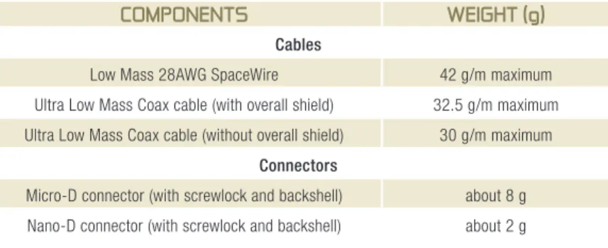
COMPONENTS WEIGHT (g)
Cables
Low Mass 28AWG SpaceWire 42 g/m maximum Ultra Low Mass Coax cable (with overall shield) 32.5 g/m maximum Ultra Low Mass Coax cable (without overall shield) 30 g/m maximum
Connectors
Micro-D connector (with screwlock and backshell) about 8 g Nano-D connector (with screwlock and backshell) about 2 g
Table of weights
E-37
LINKSAXOMACHTM Links
AXON' REFERENCES WEIGHT (g)
Cables AxOWAVETM 2.4
(Microwave coaxial cable) 12 g/m (24 g/m per way) Qfx086S
(QUASIfLEx hand-formable semi-rigid substitute)
17 g/m (34 g/m per way PCB / panel mount connectors
Variant 01 3 g
Variant 02 4 g
Variant 03 5 g
Male cable mount connectors
Variant 04 5 g
Variant 05 7 g
Variant 06 15 g
Female cable mount connectors
Variant 07 6 g
Variant 08 8 g
Variant 09 16 g
PCB surface mount connectors
Variant 10 5 g
Variant 11 8 g