Invited Review Paper / Ça
ğ
r
ı
l
ı
Derleme Makalesi
AN OVERVIEW OF ORGANIC SOLAR CELLS
Serap GÜNE
Ş
*1, Niyazi Serdar SARIÇ
İ
FTÇ
İ
21Yildiz Technical University, Faculty of Arts and Science, Department of Physics, Davutpasa-ISTANBUL 2Linz Institute for Organic Solar Cells (LIOS), Johannes Kepler University Linz, Physical Chemistry,
Altenberger Strasse, Linz-AUSTRIA Geliş/Received: 16.04.2007
ABSTRACT
The conversion of sunlight into electricity using solar cells has attracted very much attention during the last decades. Solar energy is clean, abundant and renewable. Solar cells found applications in many different fields such as in calculators, solar lamps and even on spacecraft and satellites. Historically, conventional solar cells were built from inorganic materials. The efficiency of such conventional solar cells made from inorganic materials reached up to 24 %. However, very expensive materials and energy intensive processing techniques are required. Recent efforts are put on the research for new fabrication techniques. New ways of manufacturing that can scale to large volumes and low cost are required for solar cell technologies to achive more wide spread application. A broad range of device technologies are currently being developed, including dye-sensitized nanocrystalline solar cells, polymer/fullerene blends, small molecule thin films and hybrid polymer/nanocrystal devices.
Keywords: Organic solar cells, conjugated polymers, polymer/fullerene blends.
ORGANİK GÜNEŞ PİLLERİNE GENEL BAKIŞ
ÖZET
Güneş pilleri kullanılarak güneş enerjisinin elektrik enerjisine dönüştürülmesi son yıllarda oldukça ilgi çekmiştir. Güneş enerjisi temiz, bol ve yenilenebilirdir. Güneş pilleri hesap makinelerinde, sokak lambalarında ve hatta uzay araçları ve uydularında kullanılmaktadır. Tarihsel olarak, geleneksel güneş pilleri inorganik malzemelerden yapılmaktaydı. İnorganik malzemeler kullanılarak yapılan geleneksel güneş pillerinin verimi %24’lere ulaşmaktadır. Fakat, oldukça pahalı malzemeler ve zorlu işlem süreçleri gerektirmektedir. Son zamanlarda bütün çabalar yeni üretim tekniklerinin araştırmasına harcanmaktadır. Güneş pilleri uygulamalarının geniş alanlara yayılabilmesi için büyük çapta ve ucuz üretim tekniklerinin geliştirilmesi gerekmektedir. Günümüzde, inorganik güneş pillerine alternatif olarak boya sensitizasyonuna dayalı güneş pilleri, polimer/fuleren karışımlarına dayalı organik güneş pilleri, küçük organik moleküllerle ince film güneş pilleri ve hibrid/nanokristal güneş pilleri gibi farklı teknolojilere dayalı piller üretilmektedir.
Anahtar Sözcükler: Organik güneş pilleri, konjuge polimerler, polimer/fuleren karışımları. 1. INTRODUCTION
Among the renewable energy sources solar energy has a great importance. Sun has always been the most powerful energy sources on earth. It is clean, environmentally friendly and is for free. The conversion of sunlight into electricity is performed by solar cells. The solar cell technology
*
Sigma
Vol./Cilt 25
Issue/Say
ı
1
Journal of Engineering and Natural Sciences
until recently was only based on inorganic semiconductor technology. 24 % power conversion efficiencies [1] are achievable using inorganic semiconductor technology. However, cost effective techniques are required. Organic solar cells have been the low cost alternatives of inorganic solar cells. The organic, polymer based photovoltaic elements have introduced at least the potential of obtaining cheap and easy methods to produce energy from light [2]. The possibility of chemically manipulating the material properties of polymers (plastics) combined with a variety of easy and cheap processing techniques has made polymer based materials present in almost every aspect of modern society [3]. The engineering of the electronic bandgap of organic semiconductors by chemical synthesis and mobilities as high as 10 cm2/Vs [4] made them
attractive and competitive with inorganic materials [5]. 2. BASICS OF ORGANIC SOLAR CELLS 2.1. Organic Solar Cell Materials
Organic solar cells mainly consist of two organic materials one of which is a donor (gives electron) and the other is an acceptor (accepts electrons). Conjugated polymers as donors and fullerenes as acceptors are generally employed in organic solar cells.
Organic electronic materials are conjugated molecular solids where both optical absorption and charge transport are dominated by partly delocalized π and π* orbitals [6].The
flexibility of chemical tailoring of desired properties such as band gaps as well as the easy and cheap processing and accessibility of conjugated polymers made them competitive and attractive [5].
Conjugated polymers, also known as conducting polymers, are distinguished by alternating single and double bonds between carbon atoms on the polymer backbone. Single bonds are referred to as σ bonds, double bonds contain a σ and a π bond. All conjugated polymers have a σ bond backbone of overlapping sp2 hybrid orbitals. The remaining out of plane p
z orbitals
on the carbon atoms overlap with neighbouring pz orbitals to give π bonds [7]. Although the
chemical structure of these materials are represented by alternating single and double bonds, in reality, the electrons that constitute the π bonds are described to be delocalized over the entire molecule.
Among vacuum deposited small organic molecules phthalocyanine and perylene have commonly found applications in thin film organic solar cells [8]. Phthalocyanine is a p type, hole conducting material that works as electron donor whereas perylene and its derivatives show an n type, electron conducting behaviour, and serve as electron acceptor material. A soluble derivative of C60, namely PCBM (1-(3-methoxycarbonyl) propyl-1-phenyl[6,6]C61) [9] has been synthesized
by Wudl et al and widely used in polymer/fullerene solar cells due to its solution processability which is achieved by side-chain substitution.
Important reprensentatives of hole conducting donor type semiconducting polymers on the other side, are derivatives of phenylene vinylene backbones such as poly[2-methoxy-5-(3,7-dimethyloctyloxy)]-1,4-phenylenevinylene) (MDMO-PPV), thiophene chains such as poly(3-hexylthiophene) (P3HT) and fluorene backbones such as (poly(9,9’-dioctylfluorene-co-bis-N,N’-(4-butylphenyl-1,4-phenylenediamine)(PFB).
2.2. Preparation Techniques
Research on organic solar cells focus on either solution processable organic/semiconducting polymers or vacuum deposited small organic molecules. Thermal stability is required for vacuum deposition. Small organic molecules may be more stable but less soluble as compared to conjugated polymers. Polymers will decompose under excessive heat and have a too large molar mass for evaporation [10].
(i) Spincoating (ii) doctor blading (iii) screen printing (iv) inkjet printing are the most common wet processing techniques used in organic solar cell technology.
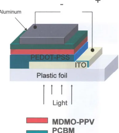
The general device structure for organic solar cells is very similar to that of the light emitting diodes (LEDs). The devices are fabricated in a sandwich geometry. As substrates, transparent, conducting electrodes (for example, glass or plastic covered with ITO) are used. ITO (indium tin oxide) is transparent and conductive but very expensive. Alternatives are searched for, such as the nanotube network electrodes [11].
On the transparent conducting substrate, PEDOT:PSS, poly(ethylene-dioxythiophene) doped with polystyrene-sulphonic acid, is commonly coated from an aqueous solution. This PEDOT:PSS layer improves the surface quality of the ITO electrode (reducing the probability of shorts) as well as facilitates the hole injection/extraction.
The active layers are then coated using solution or vacuum deposition techniques as mentioned above. Afterwards, the top electrode is evaporated. The top electrode is in general a metal with an underlayer of ultra thin lithium fluoride. The exact nature of this LiF underlayer is unknown, but certainly thicknesses such as ca 0.6 nm cannot form a closed layer. The exact role of the LiF underlayer is under controversial debate in the literature [12-15]. In photoelectron spectroscopy studies it was shown that the metal work function can be considerably reduced by evaporation of LiF layers [16].
2.3. Operation Principles
The principles of operation of organic solar cells mainly consist of the following steps: (i) absorption of light (ii) charge separation (iii) charge transport to the electrodes
Absorption of light by an organic material leads to bound electron and hole pairs which can be regarded as excitons. These excitons have to be separated into free charge carriers. A driving force is necessary for the charges to reach the electrodes. In a donor-acceptor junction, generally a gradient in the chemical potentials of electrons and holes (quasi Fermi levels of the doped phases) is built up that is the difference between the HOMO level of the donor (quasi Fermi level of the holes) and the LUMO level of the acceptor (quasi Fermi level of the electrons) [17]. The maximum open circuit voltage (Voc) is determined by this internal electric field which contributes to a field induced drift of charge carriers. Also using contacts of two metals with two different work functions, one low workfunction metal for the collection of electrons and one high workfunction metal for the collection of the holes is proposed to lead to an external field in short circuit condition within a metal-insulator-metal (MIM) picture [18]. Another driving force can be the concentration gradients of the respective charges which lead to a diffusion current. The transport of charges is affected by recombination during the journey to the electrodes, particularly if the same material serves as transport medium for both electrons and holes [17].
As a last step, charge carriers are extracted from the device through two selective contacts. A transparent indium tin oxide (ITO) coated substrate with work functions around 5 eV versus vacuum, matching the HOMO levels of most of the conjugated polymers (hole contact), is used on the illumination side, and an evaporated thin lithium fluoride/aluminium metal. contact with a workfunction of around 4.3 eV, matching the LUMO of acceptor PCBM (electron contact), is used in general on the other side.
2.4. Organic Solar Cell Architecture 2.4.1. Single Layer Devices
The first organic solar cells were based on single thermally evaporated molecular organic layers sandwiched between two metal electrodes of different work functions. The rectifying behaviour
… Overview of Organic Solar Cells
of these devices can be explained for insulators using the MIM model and for the doped materials using the formation of a Schottky barrier [10].
2.4.2. Bilayer Devices
Bilayer devices consist of p and n type semiconductors which are sequentially stacked together (see figure 1). Bilayer devices using organic semiconductors were realized for many combinations [8, 19-26]. In such devices only excitons created within the distance of 10-20 nm from the interface can reach the heterojunction interface. This leads to the loss of absorbed photons further away from the interface and leads to low quantum efficiencies [27]. Therefore, the efficiency of such devices is limited by the charge generation near the donor-acceptor interface. Using thicker films create optical filter effects of the absorbing material before the light gets to the interface, resulting in minimum photocurrent at the maximum of the optical absorption spectrum [28]. Also, the film thickness’ have to be optimized for the interference effects in the multiple stacked thin film structure [29-30].
Figure 1. Bilayer Device Configuration of an Organic Solar Cell 2.4.3. Bulk Heterojunction Devices
Bulk heterojunction is a blend of the donor and acceptor components in a bulk volume. It exhibits a donor-acceptor phase separation that each donor –acceptor interface is within a distance less
S. Güne
ş
, N. S. Sar
ı
çiftçi Sigma Vol./Cilt 25 Issue/Say
ı
1
than the exciton diffusion length of each absorbing site (see figure 2). The bulk heterojunction concept has a heavily increased (orders of magnitude) interfacial area between the donor and acceptor phases where charge separation occurs [10].
Figure 2. Bulk Heterojunction configuration in organic solar cells 2.5. Characterization of a Solar Cell Device
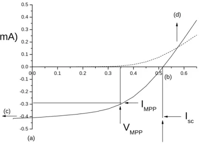
The current-voltage characteristics of a solar cell in the dark and under illumination are shown in figure 3. In the dark, there is almost no current flowing, until the contacts start to inject heavily at forward bias for voltages larger than the open circuit voltage. (a) Short-circuit current condition where the maximum generated photocurrent flows (b) Flat band condition where the photogenerated current is balanced to zero. The fourth quandrant (between (a) and (b)) the device generates power. At maximum power point (MPP), the product of current and voltage is the largest [10].
The largest power output (Pmax) is determined by the point where the product of voltage
and current is maximized. Division of Pmax by the product of Isc and Voc yields the fill factor FF.
What determines the FF is the question of how many generated charge carriers can actually reach the electrodes, when the built in field is lowered towards the open circuit voltage [17].
0.0 0.1 0.2 0.3 0.4 0.5 0.6 -0.5 -0.4 -0.3 -0.2 -0.1 0.0 0.1 0.2 0.3 0.4 0.5
I (mA)
U/V
I
scV
ocI
MPPV
MPP (a) (c) (b) (d)Figure 3. Current-voltage (I-V) curves of an organic solar cell (dark, dashed; illuminated, full line). The characteristic intersections with the abscissa and ordinate are the open circuit voltage
(Voc) and the short circuit current (Isc), respectively.
The photovoltaic power conversion efficiency of a solar cell is determined by the following formula: in sc oc e
P
FF
I
V
∗
∗
=
η
oc sc mpp mppV
I
V
I
FF
∗
∗
=
where Voc is the open circuit voltage, Isc is the short circuit current, FF is the fill factor and Pin is
the incident light power density, which is standardized at 1000 W/m2 for solar cell testing with a
spectral intensity distribution matching that of the sun on the earth`s surface at an incident angle of 48.20, which is called the AM 1.5 spectrum [31]. I
mpp and Vmpp are the current and voltage at
the maximum power point in the fourth quadrant of the current-voltage characteristics.
Generally, the open circuit voltage (Voc) of a MIM device is determined by the
difference in work functions of the two metal contacts [18]. However, in a p-n junction the maximum available voltage is determined by the difference of the quasi Fermi levels of the two charge carriers that is n-doped semiconductor energy level and p-doped semiconductor energy level, respectively [17]. In organic solar cells the open circuit voltage is found to be linearly dependent on the highest occupied molecular orbital HOMO level of the donor (p-type semiconductor quasi Fermi level) and lowest unoccupied molecular orbital LUMO level of the acceptor (n-type semiconductor quasi Fermi level) [32-33].
An experimentally accessible value is the external quantum efficiency or incident photon to current efficiency (IPCE) which is simply the number of electrons collected under short
S. Güne
ş
, N. S. Sar
ı
çiftçi Sigma Vol./Cilt 25 Issue/Say
ı
1
circuit conditions, divided by the number of incident photons. IPCE is calculated using the following formula: in sc
P
I
IPCE
*
*
1240
λ
=
where λ [nm] is the incident photon wavelength, Isc [µA/cm2] is the photocurrent of the device
and Pin [W/m2] is the incident power.
2.6. Stability
A rapid photooxidation/degradation occurs especially under the influence of light and by simultaneous exposure to oxygen and/or water vapour. Protection from air and humidity is necessary to achieve long device lifetimes [34].
The analysis of degradation kinetics by Neugebauer et al [35] showed that the high degradation rate of the conjugated polymer under influence of light and oxygen is significantly decreased when the polymer is mixed with fullerenes (as used in bulk heterojunction solar cells). The stability of the conjugated polymer in a mixture, which forms a charge transfer donor and acceptor couple, is higher than the stability of single component devices, e.g. polymer light emitting diodes, where the conjugated polymer was found to degrade within minutes under oxygen influence [36].
MDMO-PPV/C60-PCBM solar cells show also a significant nanomorphological
degradation [37]. At elevated temperatures, the PCBM molecules can diffuse through the MDMO-PPV matrix and form large crystals and thereby increases the dimension of the phase separation [38, 39-40]. This nanomorphological instability can be fixed by post production cross linking of the components, to prevent their diffusion [41]. As in the case of P3HT/PCBM bulk heterojunction solar cells, thermal annealing was used to produce and stabilize an optimum nanoscale interpenetrating network with crystalline order of both components. Excessive heat treatment will again destroy this nanomorphology. P3HT/PCBM blends show much better stability where efficiency changed less than 20 % during 1000 hours of light soaking at 70 0C
under an inert atmosphere [42]. This result demonstrates that operational stabilities for different consumer products are within reach.
2.7. Organic Solar Cells Using Conjugated Polymer and Fullerenes
Since the report of a molecular thin film organic solar cells by Tang [8] several concepts have been introduced using small molecules [8,22], conjugated polymers [43], conjugated polymer blends [26,44-45], polymer-small molecule bilayers [23,24] and blends [8,46-47] or combinations of organic-inorganic materials [48-49]. The majority of efficient organic solar cells make use of an interpenetrating network of electron donor and acceptor, the so-called bulk heterojunction concept. In bulk heterojunction organic solar cells, two different organic materials with donor and acceptor properties are mixed to create a composite material that is capable of generating charges under illumination, followed by transporting and collecting these photogenerated charges into an external circuit [8,26,49]. Photoinduced electron transfer from donor type semiconducting polymers onto acceptor type polymers or molecules, such as C60 [50] is the basic phenomenon
utilized in the organic solar cells.
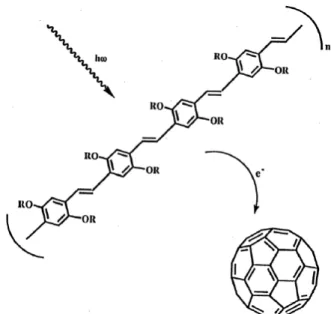
Using photoinduced electron transfer at an interface between a semiconducting donor layer, poly(2-methoxy,5-(2’-etyhl-hexyloxy)-p-(phenylene vinylene) or MEH-PPV (see figure 4), and an acceptor C60 film, diodes were demonstrated with rectification ratios on the order of 104.
Figure 4. Photoinduced electron transfer from polymer to fullerene.
The challenge in bulk heterojunction solar cells is to organize donor and acceptor materials such that their interface area is maximized [46,51], while typical dimensions of phase separation are within the exciton diffusion range and continious, preferably short, pathways for transport of charge carriers to the electrodes are ensured [42].
To enhance charge transport within the interpenetrating networks, high charge carrier mobility for both holes and electrons is required. The general approach to enhance charge carrier transport in organic and polymer materials is increasing the mesoscopic order and crystallinity. Hence, a nanoscale interpenetrating network with crystalline order of both constituents seems a desirable architecture for the active layer of polymer photovoltaic devices [42,52]. Eventually, the electronic band gaps of the materials in the photoactive layer should be tuned to harvest more light from the solar spectrum [42].
It has been shown that comparable efficiencies can be obtained for photovoltaic devices produced from alkoxy substituted poly[2-methoxy-5-(3’, 7’-dimethyloctyloxy)-1,4-phenylene vinylene) (PPVs) with 1-(3-methoxycarbonyl)propyl-1-phenyl-[6,6]-methanofullerene (PCBM) and also with C60 [46]. Since the discovery by Shaheen et al that solar cells with a power
conversion efficiency of 2.5 % under AM 1.5 conditions can be obtained by using chlorobenzene as a solvent for spincasting[46] this combination of materials became the subject of detailed studies. The dramatic increase in power conversion efficiency from 0.9 % to 2.5 % due to change of the solvent from which the polymer-fullerene solution was spincast, was assigned to changes in the morphology [46].
The high performance of the bulk heterojunction solar cells was achieved by blending MDMO-PPV/PCBM blends in 1:4. However, a direct transfer of this recipe to other systems is not straightforward, therefore a morphology optimization, in which choice of solvent is only one parameter, should be performed for any combination of materials [53].
It was recognized that morphology and molecular organization is a key issue. To obtain a deeper insight in the relation between morphology and performance of polymer/fullerene bulk heterojunction solar cells both polymer and fullerene have to be characterized [50,54]. Several studies have been done to understand the relation between the morphology of
MDMO-S. Güne
ş
, N. S. Sar
ı
çiftçi Sigma Vol./Cilt 25 Issue/Say
ı
1
PPV/PCBM blends and the solar cell performance [38-40,50,55]. The morphology of the photoactive polymer-fullerene blend can be affected by controlling several production parameters during the film formation or by treatments afterwards. Experimentally the following parameters have been identified as most significant for their influence on the nanoscale morphology in these polymer-fullerene blends: the spin casting solvent, the composition between polymer and fullerene, the solution concentration, the controlled phase separation and crystallization induced by thermal annealing, and the chemical structure of the materials.
A full understanding of the charge carrier generation, transport and recombination mechanisms is very important in order to be able to develop and synthesize the materials with required properties for efficient organic solar cells.
Charge carrier mobility in bulk heterojunction solar cells has been studied using several methods such as time of flight (TOF) [56], or calculate from the transfer characteristics of field effect transistor (FET) [57,58]. These results showed that the electron mobility and the hole mobility are unbalanced. Space charge limited current measurements showed that the mobility of holes in MDMO-PPV thin films is several orders of magnitude lower than electrons in PCBM thin films [59].
Another method for the determination of charge carrier mobility and recombination in bulk heterojunction solar cells was chage extraction by linear increase of voltage (CELIV) technique. In the CELIV technique the equilibrium charge carriers are extracted from a dielectric under a reverse bias voltage ramp. The mobility of extracted charge carriers is calculated from time when the extraction current reachs its maximum. In contrary to TOF, the CELIV technique can be used to determine charge carrier mobility in samples with only a few hundred nanometer thickness [60-65].
Although it has been shown that comparable efficiencies can be obtained for photovoltaic devices obtained from PPV derivatives and PCBM blends, in the context of technological applications among many conjugated polymers, poly(3-alkylthiophenes) have been found to be a special class of polymers with good solubility, processability and environmental stability [66-67].
Regioregular poly(3-alkylthiophenes) (P3AT) (P3HT:poly(3-hexylthiophene), P3OT:poly(3-octylthiophene), P3DDT:poly(3-dodecylthiophene) (see figure) were studied as electron donors in polymer solar cells.
3. STRATEGIES FOR IMPROVEMENT 3.1. Low Bandgap Polymers
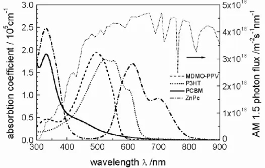
One limiting factors in bulk heterojunction solar cells is the relative low current density, which is due to the poor spectral match between the absorption of the photoactive layer and the solar emission (see figure 5)[69].
Most conjugated polymers have a band gap ≥ 1.9 eV. As a consequence only absorb at wavelengths < 650 nm. C60 fullerene derivatives also have very low absorption coefficients
except the UV region. To improve the utilization of the solar light, dedicated low band gap materials need to be developed [69]. In order to get more efficient devices, materials absorbing in the maximum of the solar photon flux, between 600 and 800 nm, are desirable. The search and development of such materials is one of the important topics for polymer bulk heterojunction solar cells [70].
Since the band gap in conjugated polymers is related with the single/double bond length alternation tuning of the band gap can be achieved by alternating electron-donating and electron accepting units along the polymer backbone [71].
Figure 5. Comparison of absorption spectra of different organic materials with the solar photon flux.
Materials such as regioregular poly(3-4-(1”,4”,7”-trioxaoctyl)phenyl)-thiophene) PEOPT [72-74] which is specific case where both nanocrystalline and partially crystalline phases are metastable and where the non-crystalline phase can be transferred into partially crystalline one easily was one of the low bandgap polymers that drew attention [70] Photovoltaic devices of PEOPT with fullerene acceptor have been demonstrated in bilayer with C60[75] as well as for
bulk heterojunction blends with PCBM. Bulk heterojunction type of devices by blending two distinct forms of PEOPT with PCBM short circuit currents up to 0.5 mA/cm2 was achieved [70].
Another choice of material for low bandgap polymers was polyfluorenes. Polyfluorene-benzothiadiazol-copolymers show electron accepting properties [76] and are used in polymer-donor/polymer-acceptor bulk heterojunction solar cells [77]. However, the efficiencies of such devices are still limited due to the high bandgap of polyfluorene (~2.4 eV).
New fluorine based copolymer poly(2,7-(9-(2`-ethylhexyl)-9-hexyl-fluorene)-alt -5,5-(4`,7`-di-2-thienyl-2`,1`,3`-benzothiadiazole)) PFDTBT which has a red-shifted absorption as compared to simple polyfluorenes was introduced by Svennson et al. Devices with PFDTBT/PCBM blends showed 2.2 % power conversion efficiencies [78].
PTPTB, consisting of alternating electron rich N-dodecyl-2,5-bis(2’-thienyl)pyrrole (TPT) and electron deficient 2,1,3-benzothiadiazole (b) units, was another choice of low bandgap polymers for application as an electron donor in bulk heterojunction solar cells [70, 79-80]
Brabec et al [81] also demonstrated the implementation of a low band gap polymer poly-N-dodecyl-2,5,-bis(2’-thienyl)pyrrole,2,1,3-benzothiadiazole (PTPTB) into plastic solar cells and light emitting diodes (LED)s. They demonstrated electroluminescence from PTPTB in the near IR peaking at 800 nm and sensitization for the PTPTB light emitting diodes via energy transfer from MDMO-PPV. The devices employing PTPTB as electron donor exhibited short circuit current of 3 mA/cm2 and the fill factor was 0.37 leading to a power conversion efficiency
of ~ 1%.
The absorption of the low bandgap polymers are shifted to the red part of the visible spectrum or even to the near infrared. However, the absorption in the blue or green part of the spectrum is diminished. A solution for this problem is to add an additional component to the blend such as an organic dye molecule or a wide bandgap conjugated polymer, absorbing in this high energy region [70].
PTPTB was sensitized with MDMO-PPV and nile red in a study reported by Winder et al [82-83]. The low bandgap guest material is dispersed in the wide bandgap host material. The photoluminescence of the low bandgap material, even at low concentration, is observed and the photoluminescence of the wide bandgap material is quenched [70]. This was observed in the case of MDMO-PPV and nile red in combination with PTPTB [82]. Such energy transfer systems were used in light emitting diodes to sensitize the luminescence of low bandgap materials [84-86]. 3.2. Polymer/Polymer Solar Cells
Inspired by the developments of conjugated polymer/fullerene bulk heterojunctions, similar systems such as blends of two conjugated polymers are examined. However, these systems achieved considerably less attention although they might have the potential to be implemented in inexpensive, large area photovoltaic systems.
Although bulk heterojunctions prepared from a blend of two conjugated polymers [26,45] have not attracted as much interest as that of blends from a conjugated polymer and a fullerene, the former concept has several advantages. In a polymer blend, both active materials can exhibit a high optical absorption coefficient and could cover complementary parts of the solar spectrum. Furthermore, it is relatively easy to tune both components individually to optimise optical properties, charge transfer and charge collection processes. On the other hand, polymer blends have an intrinsic tendency to phase separate. These phase-separated domains usually have dimensions of several microns and are thus not suitable for polymeric cells. The biggest challenge for this concept is to identify well-conducting n-type polymers, finding a combination in which two polymers have complementary absorption spectra and the right morphology for efficient charge generation and collection [87].
3.3. Donor-acceptor ‘double cable’ Polymers
The concept of ‘double cable’ polymers has been introduced in order to have a control on the morphology at the molecular level [88]. By attaching the electron acceptor moieties directly to the conjugated backbone by covalent bonds phase separation in these materials is prevented.
Figure 6. Schematic representation of ‘double cable’ polymers. The charge carriers generated by photoinduced charge transfer can be in principle transported within one molecule, therefore
termed as a ‘molecular heterojunction’.
e
h
+An electron created by photoinduced electron transfer is expected to be transported by hopping between the acceptor moieties; in this case the high mobility of the remaining hole on the conjugated chain can be utilized in transporting the positive charge.
Although several double cable materials exhibiting interesting photophysical properties have been explored the efficiency of such devices can not catch up the efficiency of bulk heterojunction organic solar cells probably due to fast recombination or inefficient interchain transport [17].
3.4. Hybrid Solar Cells
A hybrid solar cell consists of a combination of both organic and inorganic materials and therefore, combines the uniqe properties of inorganic semiconductors with the film forming properties of the conjugated polymers [89]. Organic materials usually are inexpensive, easily processable and their functionality can be tailored by molecular design and chemical synthesis. On the other hand, inorganic semiconductors can be manufactured as processable nanoparticulate colloids. By varying the size of the nanoparticles their bandgap can be tuned and therefore the absorption range can be tailored [90].
An effective strategy for hybrid solar cell fabrication is to use blends of nanocrystals with semiconductive polymers as bulk heterojunction [91-93]. Excitons created upon photoexcitation are separated into free charge carriers very efficiently at interfaces between organic semiconductors and inorganic semiconductor nanoparticles in a hybrid composite thin film. The solubility of the n-type and p-type components in the same solvent is an important paramater of the construction of hybrid solar cells. Hybrid solar cells have been demonstrated in conjugated polymer blends containing CdSe [91,93-94], CuInS2 [89,92], CdS [49] or PbS [95-96]
nanocrystals. 4. CONCLUSIONS
As previously described, the efficiency of a solar cell is given by the open circuit voltage (Voc)
times the short circuit current density (Jsc) times the fill factor (FF) divided by the incident light
intensity. The limiting efficiency of a bulk heterojunction can be determined as a function of the bandgap and the LUMO level of the donor [97].
The theoretical efficiency calculation studies by Scharber et al suggest that besides the reduction of the band gap, new donor materials must be designed to optimize the LUMO since this parameter dominantly drives the solar cells efficiency. An important message is that optimized open circuit voltage is a prerequisite to achieve certain device efficiencies however, it is not sufficient [97]. In addition the charge carrier mobility of electrons and holes in the donor-acceptor blend must be high enough to allow efficient charge extraction and a sufficient value for FF. The highest energy conversion efficiencies predicted by Scharber et al are in the range of 10 % [97]. This number appears to be achievable although donor material comprising of all the required material properties has not yet been prepared [97].
Besides the optimization of the donor properties several other strategies are investigated to increase the efficiency such as: [70]
• Synthesis and development of low bandgap polymers
• Synthesis and development of new electron accepting materials
• Tandem solar cells with several layers with different materials of different bandgaps
• The use of light scattering nano or micro particles embedded in the optically active layer to enhance the optical pathways in the film due to scattering
• Light trapping mechanisms on thin active layers of polymeric materials with simple patterning technique [98]
• Hybrid solar cells combining the properties of inorganic semiconductor nanoparticles with conjugated polymers. The absorption range can be tuned by tuning the size of the inorganic nanoparticles [89-96]
• Dye sensitized solar cells (DSSCs), which use organic dyes with absorption onsets around 800 nm on a nanoporous electrode, typically TiO2. For liquid electrolyte DSSCs, power
conversion efficiencies of 10 % were demonstrated [48]. Recently, efficiency of 4 % replacing the liquid electrolyte by an organic hole transport layer was reported [99].
REFERENCES
[1] Green M, Progress in Photovoltaics, 9, 123, 2001.
[2] Sariciftci, N. S., Smilowitz, L., Heeger, A. J., Wudl, Science, Vol. 258, 1474, 1992.
[3] Spangaard, H.; Krebs, F., Sol. Energy Mat. Sol. Cells, Vol. 83, 125,2004. [4] Dimitrakopoulos, C.D., Malenfant, PRL., Adv. Mat., Vol. 14, 99, 2002. [5] Sariciftci, N. S., Materials Today, Vol. 36, 1369, 2004.
[6] Nelson, J., Curr. Opin. İn Solid State Mat. Sci., Vol. 6, 87, 2002.
[7] Handbook of Conducting Polymers; Vol 1-2, edited by T. A. Skotheim, (Marcel Dekker Inc., NewYork, 1986).
[8] Tang, C.W., Appl. Phys. Lett., Vol. 48, 183, 1986. [9] Wudl, F., Acc. Chem. Rev., Vol. 25, 157161, 1992.
[10] Hoppe, H., Sariciftci, N.S., J. Mat. Chem., Vol. 19, 1924, 2004.
[11] Rowell, M.W., Topinka, M.A., McGehee, M., Prall, H.J., Dennler, G., Sariciftci, N.S., Hu, L., Gruner, G., Appl. Phys. Lett., Vol. 88, 233506, 2006.
[12] Brabec, C.J., Shaheen, S.E., Winder, C., Sariciftci, N.S., Denk, P., App. Phys. Lett., Vol.
80, 1288,2002.
[13] Hung, L.S., Tang, C.W., Mason, N.G., App. Phys. Lett., Vol. 70, 152,1997.
[14] Jabbour, G.E., Kawahe, Y.; Shaheen, S.; Wang, J.F.; Morell, M.M.; Kippelen, B.; Peyghembarian, N., Appl. Phys. Lett., Vol. 71, 1762,1997.
[15] Shaheen, S.; Jabbour, G.; Morrell, M.; Kawabe, Y.; Kippelen, A.; Peyghambarian, N.; Nabar, M.F.; Schlaf, R.; Mash, E.A.; Armstrong, N.R., J. App. Phys., Vol. 84, 2324, 1998.
[16] D. Jong, M. P., Friedlein, R. W., Osikowicz; Salaneck, W. R., Fahlman, M. Mol. Cryst. Liq. Cryst., Vol. 455, 193,2006.
[17] Mozer, A.; Sariciftci, N.S., C.R. Chimie, Vol. 9, 568, 2006. [18] Parker, I. J. Appl. Phys., Vol., 75, 1656,1994.
[19] Tsuzuki, T.T., Shirota, J., Rostalski, J., Meissner, D. Sol.En. Mat. Sol. Cells, Vol. 61, 1, 2000.
[20] Uchida, J. X., Rand, B.P., Forrest, S.R., Appl. Phys. Lett, Vol. 84, 4218,2004.
[21] Zhou, X., Blochwitz, J., Pfeiffer, M., Nollau, A., Fritz, T., Leo, K. Adv. Func. Mat., Vol. 11, 310,2001.
[22] Wöhrle, D., Meissner, D. Adv. Mat., Vol. 3, 129,1991. [23] Jenekhe, S. A., Yi, S., App. Pyhsics Lett., Vol. 77, 2635,2000.
[24] Breeze, A. J., Salomon, A., Ginley, D.S., Gregg, B. A., Tillmann, H., Hoerhold, H. H. Appl. Phys. Lett., Vol. 81, 3085,2002.
[25] Sariciftci, N.S., Braun, D., Zhang, C., Srdanov, V.I., Heeger, A.J., Stucky, G., Wudl, F. Appl. Phys. Lett., Vol. 62,585, 1993.
[26] Halls, J. J. M., Walsh, C. A., Greenham, N. C., Marseglia, E. A., Friends, R. H., Moratti, S. C., Holmes, A. B. Nature, Vol. 78, 451, 1995.
[27] Winder, C., Sariciftci, N.S. J. Mat. Chem., Vol. 14, 1077,2004.
[28] Harrison, M.G., Gruener, J., Spencer, G.C.W., Phys. Rev. B, Vol. 55,7831,1997. [29] Petterson, L.A.A., Roman, L.S., Inganas, O., J.App.Phys., Vol. 86,487,1999.
[30] Rotalsky, J., Meissner, D., Sol.En.Mat.Sol.Cells, Vol. 63, 37,2000.
[31] Rostalski,J., Meissner,D., Solar Energy Mater. Solar Cells, Vol. 61, 87, 2000.
[32] Brabec, C.J., Cravino, A., Meissner, D.; Sariciftci, N.S., Fromherz, T., Minse, M., Sanchez, L., Hummelen, J.C., Adv. Func. Mat., Vol. 11, 374,2001.
[33] Scharber, M., Mühlbacher, D., Koppe, M., Denk, P., Waldauf, C., Heeger, A.J., Brabec, C., Adv. Mat., Vol. 18, 789, 2006.
[34] Kroon, J.M.; Veenstra, S.C.; Sloof, L.H.; Verhees, W.J.H.; Koetse, M.M.; Sweelssen, J.; Schoo, H.F.M.; Beek; W.J.E; Wienk, M.M.; Janssen, R.A.J.; Yang, X.; Loos, J.; Mihailetchi, V.D.; Blom, P.W.M.; Knol, J.; Hummelen, J.C. Abst., European Solar En.Conf., 2005.
[35] Neugebauer, H. Elec. Chem. Soc. Proc., Vol. 12, 19,2002.
[36] Liedenbaum, A.J.F., Vleggaar, J.J.M., Philips Journ. of Res., Vol. 51, 511, 1998. [37] Schuler, S., App. Phys. A, Vol. 79, 37, 2003.
[38] Hoppe, H., Glatzel, T., Niggemann, M., Schwinger, W., Schaeffler, F., Hinsch, A., Lux- Steiner, M., Sariciftci, N. S., Thin Solid Films, Vol. 511-512, 587, 2005.
[39] Hoppe, H., Niggemann, M., Winder, C., Kraut, J., Hiesgh, R., Hinsch, A., Meissner, D., Sariciftci, N. S., Adv. Func. Mat., Vol. 14, 1005,2004.
[40] Yang, X., Van Duren, J. K. J., Janssen, R. A. J., Michels, M. A. J., Loos, J. Macromolecules, 37, 2151,2004.
[41] Drees, M., Hoppe, H., Winder, C., Neugebauer, H., Sariciftci, N.S., Schwinger, W., Schäffler, F., Topf, C., Scharber, C., Gaudiana, R. Journ. of Mat. Chem., Vol. 15, 5158,
2005.
[42] Yang, X., Loos, J. Veenstra, S. C., Verhees, W. J. H., Wienk, M., Kroon, M., Michels, M. H. J., Janssen, R. A. J., Nanoletters, Vol.5, 579,2005.
[43] Antonradis, H., Hsich, B. R., Abhowitz, M. A, Jenekhe, S. A., Stolka, M., Synth. Metals, Vol. 62, 265,1994.
[44] Granström, M., Petritsh, K., Arias, A.C., Lux, A., Andersson, M.R., Friend, R.H., Nature, Vol. 395, 257,1998.
[45] Yu, G., Heeger, A. J., J. App. Physics, Vol. 78, 4510,1995.
[46] Shaheen, S., Brabec, C. J., Sariciftci, N. S., Padinger, F., Fromherz, T., Hummelen, J. C. App. Phys. Lett., Vol. 78, 841,2001.
[47] Dittmer, J. J., Morseglia, E. A., Friend, R. H., Adv. Mat., Vol. 12, 1270,2000. [48] O`Reagan, B., Graetzel, M., Nature, Vol. 353, 737,1991.
[49] Greenham, N. C., Peng, X., Alivisatos, A.P., Phys. Rev. B, Vol. 54, 17628,1996. [50] Van Duren, J., Yang, X., Loos; J., Bulle-Lieuwma, C. W. T., Sievel, A. B., Hummelen, J.
C., Janssen, R. A. J., Adv. Func. Mat., Vol. 14, 425, 2004.
[51] Wienk, M:; Kroon, J. M.; Verhees, W. J. H.; Hummelen, J. C.; Van Hal, P. A.; Janssen, J. J. Of Angewante Chemie Int. Ed., Vol. 42, 3371,2003.
[52] Mende, L. S.; Fechtenkötter, A.; Müllen, K.; Moons, E.; Friend, R. H.; Mackenzie, J. D. Science, Vol. 293, 1119, 2001.
[53] Riedel, I. Dyakonov, V. Phys. Stat. Sol., Vol. 201, 1332,2004.
[54] Yokoyama, H.; Kramer, E. J.; Rafailovich, M. H.; Sokolov, J.; Schwarz, S. A. Macromolecules, Vol. 31, 8826,1998.
[55] Gebeyehu, D.; Brabec, C. J.; Padinger, F.; Fromherz, T.; Hummelen, J. C.; Badt, D.; Schindler, H.; Sariciftci, N. S. Synth. Metals, Vol. 118, 1,2001.
[56] Kim Y.; Cook, S.; Choulis, S. A.; Nelson, J.; Durrant, J. R.; Bradley, D. D. Chem. Mat., Vol. 16, 4812,2004.
[57] Sirringhaus, H.; Brown, P. J.; Friend, R. H.; Nielsen, N. M.; Bechgerard, K.; Langeveld, B. M. W., Spiening, A. J. H.; Janssen, R. A. J.; Meijer, E. W.; Herwig, P.; De Leeuw, D. M. Nature, Vol. 401, 685,1999.
[58] Kline, R. J., Mcgehee, M. D., Kadnikova, E. N., Liu, J. S., Frechet, J. M. J. Adv. Mat., ,
15, 1519, 2003.
[59] Goh, C., Kline, R. J., McGehee, M. D., Kadnikova, E. N., Liu, J. S., Frechet, J. M. J. App. Phys. Lett., Vol. 86, 122110, 2005.
[60] Mozer, A., PhD thesis, Linz, 2004.
[61] Mozer, A. J., Dennler, G., Sariciftci, N. S., Westerling, M., Pivrikas, A., Österbacka, R., Juska, G. Phys. Rev. B, Vol.72, 35217, 2005.
[62] Pivrikas, A., Juska, G., Mozer, A. J., Scharber, M., Karlauskas, A., Sariciftci, N. S., Stubb, H., Österbacka, R. Phys. Rev. Lett., Vol. 94, 176806, 2005.
[63] Mozer, A. J., Sariciftci, N. S., Lutsen, L., Vanderzande, D., Österbacka, R., Westerling, M., Juska, G. Appl. Phys. Lett., Vol. 86, 112104, 2005.
[64] Mozer, A. J., Sariciftci, N. S., Pivrikas, A., Österbacka, R., Juska, G., Brassat, L., H. Phys. Rev. B Vol. 71, 35214, 2005.
[65] Mozer, A., Sariciftci, N. S. Chem. Phys. Lett., Vol. 389, 438, 2004.
[66] Chirvaze, D.; Chiguvare, Z.; Knipper, M.; Parisi, J.; Dyakonov, V.; Hummelen, J. C. J. Appl. Phys., Vol. 93, 3376, 2003.
[67] Chirvaze, D.; Parisi, J.; Hummelen, J. C.; Dyakonov, V. Nanotechnology, Vol. 15, 1314, 2004.
[68] AlIbrahim, M., KlausRoth, H., Schroedner, M., Kalvin, A., Zhokhavets, U., Gobsch, G., Scharff, P., Sensfuss, S. Organic Electronics, Vol. 6, 65, 2005.
[69] Wienk, M. M., Struijk, M. P., Janssen, R. A. J. Chem. Phys., Vol. 422, 488, 2006 [70] Winder, C., Sariciftci, N. S. J. of Mat. Chemistry, Vol. 14, 1077,2004.
[71] Roncali, J. Chem. Rev., Vol. 97, 173, 1997.
[72] Aasmidtrei, K. E., Samenelsen, E. J., Mamno, W., Svensson, M., Andersson, M. R., Pettersson, L., Inganäs, O. Macromolecules, Vol. 33, 5481, 2000.
[73] Andersson, M. R., Thomas, O., Mamno, W., Svensson, M., Theander, M., Inganäs, O. J. Of Mat. Chem., Vol. 9, 1933, 1999.
[74] Brabec, C. J., Winder, C., Scharber, M. C., Sariciftci, N. S., Hummelen, J. C., Svensson, M.; Andersson, M. R. J. Chem. Phys., Vol. 15, 7235, 2001.
[75] Roman, L. S., Mamno, W.; Pettersson, L. A. A.; Andersson, M. R.; Inganäs, O. Adv. Mat., Vol. 10, 774, 1998.
[76] Pacios, R., Bradley, D. D. Synth. Metals, Vol. 127, 261, 2002.
[77] Ramsdale, C. M.; Barler, J. A.; Arias, A. C.; Mackenzie, J. D.; Friend, R. H.; Greenham, N. C. J. App. Physics, Vol. 52, 4266, 2002.
[78] Svensson, M.; Zhang, F.; Veenstra, S. C.; Verhees, W. J. H.; Hummelen, J. C.; Kroon, J. M., Inganäs, O.; Andersson, M. R. Adv. Mat., Vol. 15, 988, 2003.
[79] Dhabalan, A., Van Hal P. A, Van Duren, J. K. J., Janssen, R. A. J. Synth. Metals, Vol. 121, 2175, 2001.
[80] Dhabalan, A., Van Duren, J. K. J., Van Hal P. A, Janssen, R. A. J. Adv. Func. Mat., Vol. 11, 255, 2001.
[81] Brabec, C. J., Winder, C., Sariciftci, N. S., Hummelen, J. C., Janssen, R. A. J. Adv. Func. Mat., Vol. 12, 709, 2002.
[82] Winder, C., Matt, G., Hummelen, J. C., Janssen, R. A. J., Sariciftci, N. S., Brabec, C. J. Thin Solid Films, Vol. 403-404, 373, 2002.
[83] Cravino, A., Neugebauer, H., Luzzati, S., Castellani, M., Petr, A., Dunsch, L., Sariciftci, N. S. J. Phys. Chem. B, Vol. 106, 3583, 2002.
[84] Yu. G., Nishino, H., Heeger, A. J., Chen, T. A., Rick, R. D. Synth. Metals, Vol. 72, 249, 1995.
[85] Tasch, S., List, E. J. W., Hochfilzer, C., Leising, G., Schlicting, P., Rohr, U., Geerts, Y., Scharf, U., Müllen, K. Phys. Rev. B, Vol. 56, 4479, 1997.
[86] Hu, B., Zhang, N., Karasz, F. J. Of App. Phys., Vol. 83, 6002, 1998.
… Overview of Organic Solar Cells
[87] Kroon, J.M., Veenstra, S.C., Sloof, L.H., Verhees, W.J.H., Koetse, M.M., Sweelssen, J.; Schoo, H.F.M., Beek, W.J.E, Wienk, M.M., Janssen, R.A.J., Yang, X., Loos, J., Mihailetchi, V.D., Blom, P.W.M., Knol, J., Hummelen, J.C. Abst., European Solar En.Conf., 2005.
[88] Cravino, A., Sariciftci, N. S. J. Mat. Chem., Vol. 12, 1931, 2002.
[89] Arici, E., Sariciftci, N. S., Meissner, D. Adv. Func. Mat., Vol. 2, 13, 2003.
[90] Weller, H. Ang. Chemie Int. Ed., Vol. 32, 41,1993.
[91] Hunyh, W., Dittmer, J., Alivisatos, A. P. Science, Vol. 295, 2425, 2002.
[92] Arici, E., Meissner, D., Schäffler, F., Sariciftci, N. S. Int. J. Photoenergy, Vol. 5, 199, 2003.
[93] Huynh, W., Peng X., Alivisatos, A. P. Adv. Mat., Vol. 11, 11, 1999. [94] Alivisatos, A. P. Science, Vol. 271, 933,1996.
[95] McDonald, S., Konstantanos, G., Zhang S., Cyr, P. W., Levira, L., Sargent, H. Nat. Materials, Vol. 4, 138, 2005.
[96] Günes, S., Fritz, K., Neugebauer, H., Sariciftci, N.S., Kumar, S., Scholes, G. Sol. En. Mat. Solar Cells, Vol. 91, 420, 2006.
[97] Scharber, M., Mühlbacher, D., Koppe, M., Denk, P., Waldauf, C., Heeger, A.J., Brabec, C. Adv. Mat., Vol. 18, 789, 2006.
[98] Roman, L. S., Inganäs, O., Granlund, T., Nyberg, T., Svensson, M., Andersson, M. R., Hummelen, J. C. Adv. Mat., Vol. 12, 189, 2000.
[99] Mende, L. S.; Graetzel M. Thin Solid Films, Vol. 500, 296, 2006.