C O H E R E N T A U G M E N T E D R E A L I T Y R E N D E R I N G
F O R M O B I L E A N D N O N - M O B I L E D E V I C E S
D O C T O R A L T H E S I S ( D I S S E RTAT I O N ) to be awarded the degree
doctor rerum naturalium (dr. rer. nat.)
submitted by kai rohmer
from naumburg (saale) (place of birth)
approved by the faculty of
mathematics/computer science and mechanical engineering, clausthal university of technology,
date of oral examination may 25, 2018
dean
Prof. Dr.-Ing. Volker Wesling
chairperson of the board of examiners Prof. Dr.-Ing. Michael Prilla
supervising tutor
Prof. Dr. rer. nat. Thorsten Grosch reviewer
Univ.-Prof. Dipl.-Ing. Dr. techn. Dieter Schmalstieg, Graz University of Technology
A C K N O W L E D G M E N T S
This thesis is product of my work in the Computational Visualistics Group at the Department of Simulation and Graphics of the Otto-von-Guericke-University Magdeburg and later as part of the Graphical Data Processing and Multimedia Group at Clausthal University of Technology, both headed by my advisor Thorsten Grosch. Therefore, it’s you Thorsten I want to start expressing my gratitude to. I’m sincerely thankful for the many opportunities you have offered me, for the support, guidance, and freedom you gave me, and for everything you taught me in all those years.
I’m very grateful to a lot of people I met during the time in Magdeburg. Thank you Tobi, my fellow student, colleague and friend, for the countless discussions and the wonderful time we spent working on inspiring and fun projects. Thanks Holger and Christian for introducing me to the exciting and highly motivating field of computer graphics. Along with Maik, Janick, Timo, Dirk, Tim, Thomas, John and Anke, it was always a real pleasure. I loved being (sort of) part of your group and I’m grateful for the very pleasant but also highly productive atmosphere, the many things I learned from you, and of course the time we spent during and after lunch. Thank you all!
Even though my time in Clausthal was much shorter, I got the chance to meet some great people I also want to show my thanks to. Thank you Andreas, for being a mentor, colleague, running partner and friend. You made life on that rainy hill very enjoyable. The same goes to Feng, Dima, and Gerrit. And also thanks for the coffee breaks!
I would like to include a special note of thanks to my other roommates Sophie and Johannes. Sharing an office with you has always been a pleasure. And of course, I thank my family and friends for the unwavering support before, after, and throughout all my studies at the university. You always have my back. Thank you so much! Finally and above all, I wish to thank my lov-ing and supportive sweetheart Franzi for her endless motivation, inspiration, confidence and patience. You make sure that I still have a life besides work and I’m extremely happy to be able to enjoy it together with you!
A B S T R A C T
The subject of this thesis is the interactive and visually coherent augmentation of live camera images. Considering the dynamic environment, the goal is to embed virtual objects seamlessly into the given image data. For this, it is necessary to precisely acquire the geometry and material properties of the real surfaces in order to subsequently perform illumination simulations in this reconstruction.
During the preparation and creation of visual effects in the film industry, this real-world information already plays a significant role and enables a believable combination of virtual and real elements. Since capturing the information is not trivial and a correct lighting simulation is time consuming, a simplified visual-ization of objects without regard to the real environment is used to achieve inter-active display rates in case of augmented reality. In many applications, such as evaluating virtual design prototypes, this simplified visualization is insufficient. The most correct rendering possible, that also considers the real surrounding of the virtual objects, is necessary to serve as a basis for decision-making.
Accordingly, this dissertation explores new approaches to capture the real-world environment of virtual objects and, based on this, to realize a coherent interactive visualization. Particular attention is paid to direct and strong indi-rect light sources, which have a significant influence on the appearance of the virtual objects. The current state of the art is based on differential rendering, in which global light transport simulations are conducted to determine the influ-ence of virtual objects on the real environment. The methods developed in the scope of this dissertation are based on that technique, too. However, they are designed to produce high-quality yet highly performant augmentations that are suitable for interactive use on mobile devices. Because of the development and dissemination of mobile devices, which provide many sensors and interaction possibilities, they became an extremely relevant platform for augmented reality solutions in various areas of our everyday life as well as for professional usage. The methods presented in this dissertation seize the potential of the mobile plat-form and use it in a way that no other previous publication has demonstrated.
The core of the presented work are two physically-based augmented reality rendering frameworks: A distributed system that outsources the acquisition of the environment and the computationally expensive extraction of light sources to a stationary PC. The resulting compact parametrization of a lightweight illu-mination model is constantly updated and transmitted to mobile devices, which use their own computing capacity for an interactive and individual presentation to the user. The second system is based on a mobile device equipped with a depth sensor. It does not require any additional hardware. The environment is recorded as a three-dimensional point cloud, which is then used as input for light simulation methods. The adaptation of GPU-based Monte Carlo rendering pro-vides a trade-off between quality and performance, and thus interactive display on mobile devices as well as a photorealistic rendering, that is otherwise known only from offline methods. Furthermore, a method for estimating unknown color transformations of cameras is presented, which is used during the scene acquisi-tion to measure surface radiance with high dynamic range. They are also used as a color adjustment between virtual and real objects, making the boundaries harder to perceive and the augmentation more seamless.
This dissertation introduces new methods that improve augmented reality rendering on mobile devices in terms of quality and performance. Thus, they improve the current state of the art and offer new possibilities for applications in many fields in which interactive and coherent visualization of virtual elements is of great importance, e.g., for the visualization of design prototypes, architecture, interior design, cultural heritage as well as in museums and exhibitions.
Z U S A M M E N FA S S U N G
Gegenstand dieser Dissertation ist die interaktive und visuell kohärente Erwei-terung von Live Kamerabildern um virtuelle Objekte. Unter Berücksichtigung der teils dynamischen Umgebung, besteht das Ziel darin, die hinzugefügten Ele-mente möglichst nahtlos in die gegebenen Bilddaten einzubetten. Hierfür ist es notwendig, die Geometrie und die Materialeigenschaften der realen Oberflächen genau zu erfassen, um anschließend Beleuchtungssimulationen durchzuführen.
Während der Vorbereitung und der Erstellung von visuellen Effekten in der Filmindustrie spielen diese realweltlichen Informationen bereits eine bedeutende Rolle und ermöglichen eine glaubhafte Kombination aus virtuellen und realen Elementen. Da das Erfassen der Informationen alles andere als trivial und eine korrekte Beleuchtungssimulation zeitaufwendig ist, wird im Falle von Augmen-ted Reality häufig auf eine stark vereinfachte Visualisierung von Objekten ohne Berücksichtigung der realen Umgebung zurückgegriffen. Dies ermöglicht das Er-reichen der zwingend erforderlichen interaktiven Darstellungsraten. In vielen Anwendungsfällen, wie z.B. dem Evaluieren von virtuellen Design Prototypen, ist diese vereinfachte Visualisierung ungenügend. Eine möglichst korrekte Dar-stellung der virtuellen Objekte in der aktuellen realen Umgebung ist notwendig, um als Entscheidungsgrundlage zu dienen.
Dementsprechend untersucht diese Dissertation neue Ansätze, um das real-weltliche Umfeld von virtuellen Objekten zu erfassen und darauf basierend, eine kohärente interaktive Darstellung zu realisieren. Besonderes Augenmerk liegt dabei auf den direkten und starken indirekten Lichtquellen, die einen wesent-lichen Einfluss auf das Erscheinungsbild der virtuellen Objekte haben. Eine Beschreibung der Lage und Intensität dieser Lichtquellen ist unabdingbar, um eine korrekte Verschattung zwischen virtuellen und realen Elementen der Sze-ne zu berechSze-nen. Während viele aktuell genutzte Verfahren anSze-nehmen, dass sich die Lichtquellen in unendlich weiter Entfernung befinden, ist es Ziel die-ser Arbeit ohne diese Annahme auszukommen und damit auch eine korrekte Nahfeldbeleuchtung zu ermöglichen. Der aktuelle Stand der Technik basiert auf Differenziellem Rendering, in dem globale Beleuchtungssimulationen durchge-führt werden, um den Einfluss von virtuellen Objekten auf die reale Umgebung zu bestimmen. Dieser Einfluss beinhaltet neben Verdeckung und Verschattung auch indirekte Beleuchtung, die durch die Reflexion von Licht zwischen realen und virtuellen Elementen entsteht. Auch die im Rahmen der vorliegenden Arbeit entwickelten Verfahren beruhen auf dieser Technik. Sie zielen aber darauf ab, qualitativ hochwertige und gleichzeitig performante Bildsynthesen zu erzeugen, die für den interaktiven Einsatz auf mobilen Geräten geeignet sind. Durch die Entwicklung und Verbreitung von mobilen Endgeräten mit einer Fülle an Senso-ren und Interaktionsmöglichkeiten, stellen diese eine äußerst relevante Plattform für die Augmented Reality Lösungen in verschiedensten Bereichen des alltägli-chen Lebens und für den professionellen Einsatz dar. Die in dieser Dissertation vorgestellten Beiträge greifen das Potenzial der mobilen Plattform auf und nut-zen es in einer Weise, die in bisher keiner anderen Publikation demonstriert wurde.
Kern der vorliegenden Arbeit sind zwei physikalisch fundierte AR Rendering Frameworks: Ein verteiltes System, welches das Erfassen der Umgebung und die rechenintensive Extraktion von Lichtquellen auf einem stationären Computer auslagert. Die resultierende kompakte Parametrisierung eines leichtgewichtigen Beleuchtungsmodelles wird permanent aktualisiert und an mobile Geräte über-tragen, die die eigenen Rechenkapazitäten für eine interaktive und individuelle Darstellung von virtuellen Objekten nutzen. Das zweite System basiert auf ei-nem mobilen Gerät mit Tiefensensor und kommt ohne zusätzliche Hardware aus.
In einer Initialisierungsphase wird die Umgebung als dreidimensionale Punkt-wolke mit Oberflächennormale und Leuchtdichte für jeden gemessenen Punkt aufgenommen. Diese Rekonstruktion wird im Anschluss als Eingabe für ver-schiedene Lichtsimulationsverfahren genutzt. Die Adaption von GPU-basiertem Monte Carlo Rendering für die Anwendung in Augmented Reality Szenarien ermöglicht einen Trade-off zwischen Qualität und Geschwindigkeit und damit sowohl interaktive Darstellung auf mobilen Geräten, als auch eine photorealisiti-sche Darstellung, die sonst nur aus Offline-Verfahren bekannt ist. Des Weiteren wird ein Verfahren zur Schätzung von unbekannten Farbtransformationen von Kameras vorgestellt, was während der Aufnahme genutzt wird, um Leuchtdich-ten mit hohem Dynamikbereich zu messen. Während der Darstellung, wird die geschätzte Transformation als Farbabgleich zwischen virtuellen und realen Ob-jekten genutzt, wodurch beide Teile visuell besser verschmelzen und die Grenzen damit schwerer wahrnehmbar werden.
Diese Dissertation stellt damit neue Verfahren vor, die Augmented Reality Darstellungen auf mobilen Endgeräten visuell als auch aus Sicht der Perfor-manz verbessern. Sie ergänzen damit den bisherigen Stand der Technik und bieten neue Möglichkeiten für Anwendungen in vielen Bereichen in denen eine interaktive und kohärente Visualisierung von virtuellen Elementen von großer Bedeutung ist, z.B. Visualisierung von Design Prototypen, Architektur, Innen-einrichtung, Denkmalpflege sowie in Museen und Ausstellungen.
C O N T E N T S 1 introduction 1 1.1 Application Areas . . . 4 1.2 Problem Statement . . . 7 1.3 Summary of Contributions . . . 8 1.4 Publications . . . 10 1.5 Outline . . . 11
2 fundamentals in light transport 12 2.1 Radiometric Quantities . . . 12
2.2 Computing Light Transport . . . 15
2.3 Spectral Radiance, Photometry and Colorimetry . . . 17
2.4 Bidirectional Scattering Distribution Functions . . . 19
2.5 The Lambertian Emitter . . . 22
2.6 Fundamental Techniques . . . 24
2.6.1 Ray Tracing . . . 24
2.6.2 Path Tracing and Monte Carlo Sampling . . . 24
2.6.3 Light Tracing . . . 26
2.6.4 Bidirectional Path Tracing . . . 27
2.6.5 Metropolis Light Transport . . . 27
2.6.6 Photon Mapping . . . 27
2.6.7 Radiosity . . . 28
2.7 Real-time Rendering . . . 29
2.7.1 Deferred Shading and Tiled Rendering . . . 30
2.7.2 Instant Radiosity . . . 31
2.7.3 Micro-Rendering . . . 32
2.7.4 Image-based Rendering . . . 34
2.7.5 Ambient Occlusion . . . 36
2.7.6 Precomputed Radiance Transfer . . . 37
2.7.7 Light Propagation Volumes . . . 41
2.7.8 Voxel Cone Tracing . . . 41
3 fundamentals in augmented and mixed reality 44 3.1 Visual Coherence . . . 45
3.2 Intrinsic Parameters . . . 47
3.2.1 The Pinhole Camera . . . 48
3.2.2 The Fish-eye Camera . . . 50
3.3 Extrinsic Parameters . . . 51
3.3.1 Marker Tracking . . . 53
3.3.2 Natural Feature Tracking . . . 58
3.3.3 3D Object Tracking . . . 60
3.4 Radiometric Calibration . . . 61
3.5 Visual Displays . . . 64
3.5.1 Methods of Augmentation . . . 64
3.5.2 Properties of AR Displays . . . 65
3.5.3 Visual Displays in this Thesis . . . 67
4 overview of coherent augmented reality 68 4.1 Environment Reconstruction . . . 69
4.1.1 The Plenoptic Function . . . 69 4.1.2 Light Representation . . . 71 4.1.3 Geometry Reconstruction . . . 76 4.1.4 Material Reconstruction . . . 81 4.1.5 Inverse Rendering . . . 84 4.2 Differential Rendering . . . 90
4.3 Interactive Coherent Rendering . . . 93
4.3.1 Local Common Illumination . . . 94
4.3.2 Global Common Illumination . . . 97
4.3.3 Common Illumination and Relighting . . . 99
4.3.4 Camera Simulation . . . 100
4.4 Summary . . . 101
4.5 Rendering on Mobile Hardware . . . 102
5 distributed near-field illumination 104 5.1 Overview . . . 105
5.1.1 Hardware Setup and Precomputations . . . 105
5.1.2 Distributed Illumination . . . 106
5.1.3 Pipeline Overview . . . 108
5.2 Server Computations . . . 108
5.2.1 Acquiring the Radiance Atlas . . . 109
5.2.2 Splitting the Radiance Atlas . . . 110
5.2.3 Finding Direct Light Sources . . . 111
5.2.4 Compressing Indirect Light . . . 114
5.3 Rendering on the Client . . . 116
5.4 Results . . . 117
5.4.1 Comparison . . . 118
5.4.2 Evaluation of the Visual Quality . . . 120
5.4.3 Light Extraction Performance . . . 122
5.4.4 Rendering Performance . . . 123
5.4.5 Real-world Scenarios . . . 124
5.4.6 Non-Diffuse BRDFs . . . 125
5.5 Selection of Parameters . . . 128
5.6 Grid-based Indirect Illumination . . . 130
5.7 Discussion . . . 131
6 tiled frustum culling for differential rendering 133 6.1 Motivation . . . 134
6.2 Culling in Tiled Deferred Rendering . . . 135
6.3 Culling in Tiled Forward Rendering . . . 137
6.3.1 Tiled Light Lists . . . 138
6.3.2 Filling the Tiled Light Lists . . . 139
6.3.3 Compacting the Tiled Light Lists . . . 141
6.3.4 Using the Lists during Rendering . . . 142
6.4 Results . . . 143
6.4.1 Culling and Rendering Performance . . . 144
6.4.2 Transparent Virtual Objects . . . 145
6.5 Discussion . . . 147
7 natural environment illumination 149 7.1 Overview . . . 150
7.2 Color Compensation Estimation . . . 152
7.2.1 Selecting Sample Pairs . . . 152
7.2.3 Linear Map Estimation . . . 154
7.3 Capturing the Environment . . . 155
7.4 Interactive Coherent Rendering . . . 157
7.4.1 Scene Representation . . . 158
7.4.2 Virtual Object Representation . . . 159
7.4.3 Rendering the Virtual Object . . . 159
7.4.4 Differential Background Rendering . . . 160
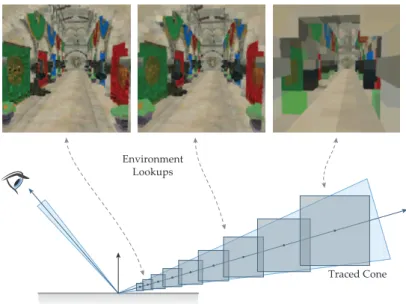
7.4.5 Extension to Cone Casts . . . 161
7.4.6 Composition . . . 162
7.5 Illumination Estimation using Sampling . . . 162
7.5.1 Caching of Samples . . . 163
7.6 Results . . . 164
7.6.1 Environment Acquisition . . . 164
7.6.2 G-Buffer Generation . . . 165
7.6.3 Scene Representation . . . 165
7.6.4 Rendering of the Virtual Object . . . 166
7.6.5 Material Estimation . . . 167
7.6.6 Differential Background Rendering . . . 168
7.6.7 Composition . . . 169 7.7 Discussion . . . 170 8 conclusion 174 8.1 Summary . . . 175 8.2 Future Work . . . 177 a appendix 180 a.1 Distributed Near-Field Illumination . . . 180
a.2 Tiled Frustum Culling for Differential Rendering . . . 180
a.3 Natural Environment Illumination . . . 180
N O M E N C L AT U R E
p Scalar value
F() Scalar-valued function
F−1() Inverse of a scalar-valued function
x Vector (column-wise) inn-D space
xT Transpose of a vector or matrix xTy Dot product (in matrix notation)
A Matrix
A−1 Inverse of a matrix
I Identity matrix
R
Setω A solid angle[sr]or the direction of an infinitesimal solid angle
cosθ The cosine of the angleθ clamped to[0, 1]
R
H+ Spherical integral over the domain of the upward hemisphere
R
H− Spherical integral over the domain of the downward hemisphere
R
H+− Spherical integral over the domain of both hemispheres
N(x) Surface normal at positionx ∂f
A C R O N Y M S
AO Ambient Occlusion
API Application Programming Interface
AR Augmented Reality
BPT Bidirectional Path Tracing
BRDF Bidirectional Reflectance Distribution Function BSDF Bidirectional Scattering Distribution Function
BSSRDF Bidirectional Surface Scattering Reflectance Distribution Function
BTDF Bidirectional Transmittance Distribution Function BTF Bidirectional Texture Function
BVH Bounding Volume Hierarchy CAD Computer-aided Design CDF Cumulative Density Function CNN Convolutional Neural Network CPU Central Processing Unit DCC Digital Content Creation DI Distance Impostor
DIT Distance Impostor Tracing DLPV Delta Light Propagation Volume DVCT Delta Voxel Cone Tracing
EM Environment Mapping
FAST Features from Accelerated Segment Test GI Global Illumination
GPU Graphics Processing Unit
GPGPU General Purpose Computation on the Graphics Processing Unit HDR High Dynamical Range
HSV Hue-Saturation-Value IBL Image-based Lighting ICP Iterative Closest Point ILF Incident Light Field IR Instant Radiosity ISM Imperfect Shadow Maps
iTMO Inverse Tone Mapping Operator LCD Liquid Crystal Display
LDR Low Dynamical Range LoD Level of Detail
LPV Light Propagation Volume
MR Mixed Reality
MLT Metropolis Light Transport
OST Optical See-Through PBR Physically-based Rendering PDF Probability Density Functions
PM Photon Mapping
PRT Precomputed Radiance Transfer RSM Reflective Shadow Map
SAR Spatial Augmented Reality SH Spherical Harmonics
SLAM Simultaneous Localization and Mapping SSDO Screen-Space Directional Occlusion SURF Speeded Up Robust Features
SVBRDF Spatially-Varying Bidirectional Reflectance Distribution Function
SVD Singular Value Decomposition TLL Tiled Light List
TMO Tone Mapping Operator VAL Virtual Area Light
VCM Vertex Connection and Merging VCT Voxel Cone Tracing
VPL Virtual Point Light VSL Virtual Spherical Light VR Virtual Reality
1
I N T R O D U C T I O NThe creation of immersive artificial worlds is part of human history for a long time, starting with stories and tales that where passed down orally, over paintings showing events in the ancient past or the far future, and literature of any kind that fascinates and absorbs the reader. Mainly driven by newer media forms, such as movies and games, virtual environments based on computer generated three-dimensional content became more and more popular in the last decades. With the technology evolving, virtual environments are getting increasingly realistic – at least in terms of visuals and sometimes audio. The degree of immersion in such artificial worlds is currently seeing a new boost by the recurring popularity of tracked head-mounted displays that allow the users to change their vantage point as they would do in the real world. The term Virtual Reality (VR) however, stands for a broader concept than just
spectating a realistic virtual world:
VR environment is one in which the participant-observer is totally
immersed in, and able to interact with, a completely synthetic world. Such a world may mimic the properties of some real-world environ-ments, either existing or fictional; however, it can also exceed the bounds of physical reality by creating a world in which the physical laws ordinarily governing space, time, mechanics, material properties, etc. no longer hold.
—MilgramandKishino[MK94] With increasing capabilities of mobile devices, these virtual worlds and their unbound possibilities can be reached at any time from any place. However, they are detached from our physical surrounding and thereby detached from our daily life [SH16]. To be able to use this technology to ease real-world problems, to provide meaningful information about complex tasks or simply to enhance collaboration and the transfer of knowledge concerning aspects in the local environment, a connection between virtual elements and our phys-ical surrounding is most desirable. This kind of connection is the intrinsic motivation behind Augmented Reality (AR).
Whereas virtual reality (VR) places a user inside a completely
computer-generated environment, augmented reality (AR) aims to present information that is directly registered to the physical envi-ronment. (AR) goes beyond mobile computing in that it bridges the
gap between virtual world and real world, both spatially and cogni-tively. With (AR), the digital information appears to become part of
the real world, at least in the user’s perception.
Creating this connection between the real and the virtual world is the great goal and some people might argue that this is done for a long time and it is well known from special effects in movies, where computer generated content is added to real-world footage [SH16]. But this is not true when considering
AR in the most widely accepted interpretation. According to Azuma, three criteria have to be fulfilled: the combination of real and virtual, interactive in real-time and registered in 3D [Azu97]. This allowsARto be used as interac-tion technique, anchored in the real world and independent from the specific technical realization. Ideally, we will have access to all kind of information without the need of any buttons or screens. Instead,ARwill allow to interact with virtual objects as we do with real ones in a very natural and intuitive way.
According to Azuma’s definition, special effects in movies lack the impor-tant aspect of interactivity. By incorporating techniques developed in the game industry, movie companies are working on interactive experiences, but mainly in the context of VR. However, video sequences with special effects that took days to compute single frames several years ago, are getting more and more feasible in real-time with today’s technology, so eventually, producing immer-sive experiences in real-time is only a matter of time. The big challenge inAR
is the augmentation of our personal environment that is not directed by movie producers. It requires sophisticated techniques to reliably understand the in-dividual, complex and more or less unknown real-world environment we are currently working and living in. Therefore, it is an interdisciplinary challenge, that involves not only computer graphics and computer vision or computer science in general, but also expertise from the individual field of application (see Section1.1).
Also because of the role of movies and games in the development process, the focus is mainly on the visual (and aural) aspects. Despite the fact, thatAR
is not restricted to visual augmentations – nor are visual super-impositions required at all, this thesis concentrates on the visual appearance of virtual objects in an augmented world. More precisely, the presented work focuses on visual coherence in augmented reality. For many years, visual coherence is one of the research topics in focus of the computer graphics community. With the goal of photorealistic augmentation, various methods have been developed to insert virtual objects into a view of the real world so that they blend in seamlessly. Sophisticated methods exist, that allow for plausible global illumi-nation light transport simulations – the foundation of photorealistic render-ing – at interactive rates, but only on non-mobile platforms. Mobile devices like smartphones and tablet PCs, that became part of our everyday life, have all properties required for AR though. They are portable and can be used wherever we need them, they have sensors that allow for registration in our 3D world and they can display the virtual elements in the live camera stream that shows the real environment. Using the integrated camera, such a device can act like a “porthole window” into an augmented real world as suggested byFitzmauriceet al. [FZC93].
In the past, when virtual objects are inserted, their appearance is often inconsistent with the real environment, especially in mobile AR. To achieve coherent augmentations, there are three major topics we need to deal with: ge-ometric registration, photge-ometric registration and camera simulation [SH16]. Geometric registration of the virtual content and the real world is the founda-tion of coherent ARapplications. It involves a pose estimation of the camera
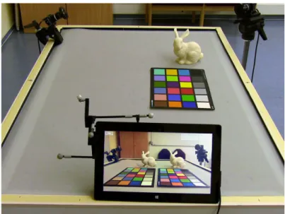
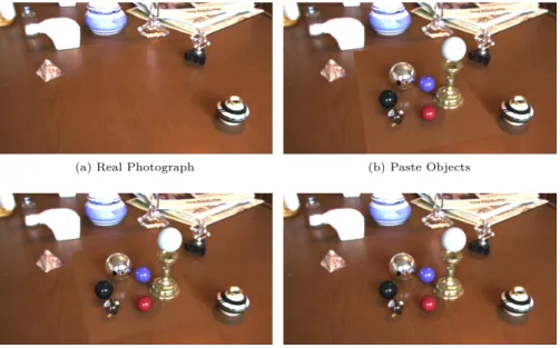
Figure 1.1: Demo Scenario for Distributed Near-Field Illumination The tablet camera shows the real world, augmented by virtual objects with consistent illumination, displayed at 27 Hz. By using a tracked device, the user can move the tablet freely in the augmented real world and interact with the inserted objects (see Chapter5).
can automatically provide several important visual cues while rendering vir-tual objects, e.g., relative size of objects and perspective. This allows us to focus on occlusions, shadows and shading to achieve a seamless blend of vir-tual and real objects. Camera simulation takes the physical behavior of the camera into account. As cameras in mobile devices cannot be compared to professional DSLR cameras – or even the human eye – in terms of quality, mainly because of size and price, we need to deal with various kinds of arti-facts that influence our view into the real world and thereby the augmented world presented to the user. While this issue is addressed in Chapter7, the main topic of this thesis is the aspect of photometric registration: It describes the interaction of light between the real world and the virtual augmentations. This involves the acquisition of the real environment including geometry, ma-terials and light – ideally, the plenoptic function introduced byAdelsonand Bergen[AB91]. Based on the captured data, light simulation approaches can be used to compute the appearance of the virtual objects in the real environ-ment and their virtual influence back on the real scene. Figure 1.1 contains a result of the approach described in Chapter 5. The virtual objects are illu-minated by the acquired environment light and thereby look very similar to their real counterparts. From the point of view of classical computer graph-ics, this is the main problem on the way of achieving a seamless blending of the perceived appearance of real and virtual objects. Especially, in dynamic environments this results in a very complex and challenging task:
Estimating real-world lighting and applying it to virtual objects is a key element of visually coherent rendering inAR. In the real world,
shadows change, as people and objects move, and lighting changes, as lamps are switched on and off.
So far, a consistent illumination that handles both dynamic scenes and dy-namic lighting conditions eluded the mobile platforms and several applications would benefit from such mobile systems. The main contributions of this thesis, presented in Chapters 5to 7, include several techniques that seek to fill this gap by providing high-quality mobileARat interactive performance.
1.1 application areas
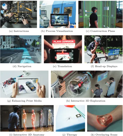
Possible applications for ARare nearly everywhere. Depending on the partic-ular use case radiometric coherent rendering of virtual objects is not always necessary as many scenarios benefit from stylized visualizations. Common ex-amples are working instructions and step-by-step guides that help users to accomplish their tasks (see Figure1.2a). This includes maintenance and
stan-(a) Instructions (b) Process Visualization (c) Construction Plans
(d) Navigation (e) Translation (f) Head-up Displays
(g) Enhancing Print Media (h) Interactive 3D Exploration
(i) Interactive 3D Anatomy (j) Therapy (k) Overlaying Scans Figure 1.2: General Applications for Augmented Reality
There are various applications in the industry as well as in the educational and medical sector, but also related to traveling and sports. Image cour-tesy of (a) VR Safety Limited, (b) Klimant et al. [KKS17], (c) Scot-tish Construction Now,(d)Daimler AG,(e)Quest Visual, Inc,(f) Re-con Instruments, (g)NMY Mixed-Reality Communication GmbH, (h) Microsoft,(i),Microsoft(j)Juanet al.[Jua+05] and(k)TU München, respectively.
dard repair procedures but also instructions in manufacturing. Besides the guidance and training of users or workers, AR can also be used for in-place visualizations of processes happening inside of machines and devices [Kol+17] (see Figure1.2b). Similar to that, we can use in-place visualization of existing or future water conduits and power supply lines to support workers and plan-ners during the construction or maintenance of buildings (see Figure1.2c).
There are various applications for travelers, including navigation by dis-playing lines and arrows directly on the street (see Figure 1.2d), labels that show the location of the next cafés around you and in-place translations of text that is written in a language you do not speak (see Figure1.2e). Related techniques are also relevant for sports, where player names can be annotated or lines, distances, trajectories and any other information useful to spectators, can be displayed while the game is running. AR can also be useful to
ath-letes themselves when considering head-up displays for cyclist or runners for instance (see Figure 1.2f).
While these examples do not necessarily require coherent rendering, other areas can benefit from it. In addition, there are applications where a coherent appearance is critical to success, and there are also cases in between. One of them is the field of education and training. The classical transfer of knowledge with the help of texts and images can be supplemented by 3D animations and interactive visualizations (see Figure1.2g). Compared to images or videos, the object of interest can be observed from arbitrary angles and manipulations by the user can help to discover functionality by trail and error without the risk of breaking anything (see Figure 1.2h). For some professionals, like surgeons, a more realistic visualization during training might help to prepare better for future real-world scenarios, which starts with anatomy classes (see Figure1.2i). There is also potential for the usage ofAR in the treatment of psychological disorders [Jua+05]. One example is the treatment of arachnophobia by con-fronting patients with their fear in a controlled situation that can be adapted to the patients progress and stopped at any time (see Figure 1.2j).
Interesting scenarios also arise with the demographic change in western societies. AR can help in the sector of informal care, by supporting family members that take care of their effected relatives at home by following pre-defined or remote instructions from experts [JP16]. Other applications in the field of medicine include overlaying medical data from various scans directly on the patients body (see Figure 1.2k). This can be used for illustration pur-poses while informing the patients about their condition or during surgery, so that the surgeon can keep his gaze on the instruments rather than turning towards monitors.
We primarily aim for applications which require correct illumination at ev-ery location in the scene, and a perceptively plausible lighting is probably not sufficient. Such applications can be found, for example, in interior design and architecture, by presenting convincing in-place visualization of the designer’s vision (see Figure 1.3a). We can also support private users, who want to re-furnish their homes and would like to know how the sideboard or sofa looks in their own living room (see Figure 1.3b). You can find several apps in the stores that allow this already, but they usually lack coherent illumination. In the field of coherent AR rendering, we are not limited to reproduce the real-world light condition for shading virtual objects. Instead, we also aim for changing real-world materials, adding new light sources like additional lamps, but also supporting the planning of a wall breakthrough for new a window for instance (see Figure1.3c). Without adding any new furniture, these examples
(a) Architecture Visualization (b) IKEA Place App (c) Wall Breakthrough
(d) Prototyping (e) AR Prototyping (f) Retail
(g) Games (h) Movie Production (i) Marketing
(j) Aged Colors (k) Damaged Reliefs (l) Stolen Art
(m) Visiting Historical Sights (n) Partial Objects Figure 1.3: Applications for Coherent Augmented Reality
PhotorealisticARcan enhance applications in architecture, home furnishing
and retail as well as the prototyping for design and development. Market-ing, movie productions and games can also benefit from improved coherence. Furthermore, new possibilities in the field of cultural heritage will emerge along with new forms of presentations in museums and exhibitions. Image courtesy of (a) Urbasee, (b) Ikea, (d) Jaguar, (e) Microsoft, (f) Re-active Reality GmbH,(g)Microsoft,(h)Disney Enterprises Inc.,(i) Microsoft,(j)dpa,(l)Museum of Stolen Art,(m)NoReal.itand (n) CIMMI Quebec, respectively.
already impact the global lighting condition within the scene. Being able to precisely predict the result would open up new possibilities.
The same applies to other design processes, for example in the automotive sector, where building real prototypes is expensive and time consuming. Vir-tual prototyping in real-world conditions would improve the decision process (see Figure1.3dand1.3e).
Similar to the furnishing example, nearly every kind of home shopping ex-perience could be enhanced by having coherentARproduct presentations, like with a sophisticatedARwardrobe (see Figure1.3f). Furthermore, the research is relevant for ARgames, as users expect more and more enhanced graphics (see Figure1.3g). CoherentARcan also be used in movie productions or in the process of creating a theater play by providing previews of the final scene and the created mood to the director at early stages (see Figure 1.3h) – besides the obvious marketing purpose (see Figure1.3i).
Another important area of application is cultural heritage and the usage in museums and exhibitions. Bringing back virtual versions of lost or de-stroyed artifacts would open up new possibilities. Visitors as well as profes-sional historians can see and discuss about how certain objects must have been looked like centuries ago before they got damaged or aged over time (see Figure1.3jto1.3n). In addition, conferred exhibits can still be displayed using virtual replicas in form of interactive 3D objects, that can be observed from all angles, rather than showing showing simple placeholder images. Of course, it is also possible to take virtual exhibits out of the museum to investigate them in an arbitrary light condition.
1.2 problem statement
WithARCore1 and ARKit2, augmented reality is getting more attention these days. Nevertheless, (photorealistic) ARhas been a topic of research for
more than 30 years now [Nak+86] and various sophisticated methods have been presented that address coherent rendering. Plausible real-time augmen-tations of live camera streams that blend seamlessly however, are not yet satisfactorily resolved, especially for mobile devices. While several methods, reviewed in Chapter 4, address partial aspects of that great goal, the state-of-the-art is still far from being able to augment arbitrary environments in an interactive, plausible and coherent fashion. To get closer to that goal and to enable the presented applications, the following problems have to be ad-dressed:
p ro b l e m 1: environment acquisition As this is the main
differ-ences to VRand the classical rendering for games and visualization purposes, the acquisition, recognition and understanding of the real-world environment is of particular importance for AR. In the context of visual coherence, the problem consists of the reconstruction of the geometry and materials of real-world objects and in determining the current light condition. Assuming that individual components do not change over time eases the problem. However, the eventual goal is to enable augmentations in fully dynamic environments. Specifically, the high dynamic range of radiance present in real environments and the complex view-dependent material properties of real surfaces are the main challenge while addressing this problem.
1 Google.ARCore. Project Website, 2017.
p ro b l e m 2: illumination of virtual objects by the envi-ronment Given a complete reconstruction of the real environment, the illumination of virtual objects can be computed by classical light transport simulations. In case of an incomplete or estimated reconstruction, the plau-sible rendering of virtual objects is not yet solved without user specified in-formation. Even when achieving correct light transport results, the perceived appearance of virtual objects may not be optimal due to properties of the sensors that acquired the environment data in the first place or due to the display component that presents the final image. For coherent augmentations, theARsystem has to account for these unavoidable limitations.
p ro b l e m 3: relighting of the real environment Inserting
virtual objects has a global impact on the light transport within the scene. Light paths are blocked or redirected when hitting the new element. This re-sults in mutual light interactions between virtual and real objects, which are notable as shadows and reflections of direct light from the sources, but also from light that bounced one or multiple times of the virtual or real surface. To determine these effects correctly requires global light transport simulations that rely heavily on a proper scene reconstruction. Given a sophisticated rep-resentation of the scene, there is still an immense computational effort – a problem shared by all areas that aim for photorealistic rendering.
p ro b l e m 4: interactivity and mobile devices Solving
Prob-lem 1 to 3 is not straightforward. Additionally, we are interested in provid-ing these coherent augmentations at interactive rates, so that a user can ex-plore and manipulate the virtual elements. To ensure this necessary property [Azu97], especially on mobile hardware, we have to concentrate on the most perceptible properties first and thereby maximize the visual coherence with the limited computational power. The essence of this problem is well known in many areas, not just computer graphics: finding a compromise between quality, performance and resource consumption.
1.3 summary of contributions
The methods developed and presented in this thesis address the aforemen-tioned problems and thereby form a step towards the goal of reaching interac-tive coherent augmented reality. This dissertation explores new methods for acquiring the illumination condition in the current scene and for making that information available to AR rendering pipelines. While focusing on visually coherent results, we concentrate on physically-based simulations that provide a common interface for future works, that build upon our methods and many other techniques in the field of physically-based rendering. The developed al-gorithms and systems are designed for the usage in interactive systems, but also for scalability to have a long term impact and relevance for future, more powerful and capable hardware generations.
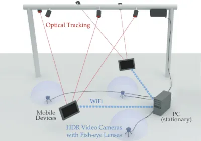
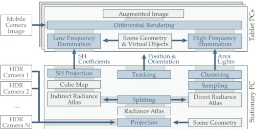
distributed near-field illumination In this work, we present a, distributed illumination approach for consistent illumination of virtual objects with direct light, indirect light (color bleeding) and shadows of primary and strong secondary sources. Due to constraints of the mobile device, we split the computation into two parts: First, the real-world radiance is captured by a number of High Dynamical Range (HDR) video cameras that are placed at
different locations in the scene such that each part of the scene is visible to at least one camera (addressingProblem 1). The acquired image data is evaluated on a stationary PC and parameters for an illumination model are transferred to the mobile devices. Here, in the second step, the consistent illumination for the virtual objects is computed and displayed to the user at interactive frame rates (Problem 2 and 4). This also involves shadows cast from virtual onto real objects and vice versa, which is part ofProblem 3. In summary, our main contributions are:
– a new distributed approach for interactive photorealistic AR under dynamic real-world environment lighting
– and a lighting model for correct near-field illumination with compact parametrization to be transferred to one or multiple display devices. tiled frustum culling In this part, we mainly focus on Problem 4 and show how to reduce the computational cost per reconstructed light using a combination of tile-based rendering and frustum culling techniques. Assuming a lighting model based on discrete sources, like the one in our distributed illumination technique, we identified the possible region of direct influence by such a light as the shadow volume defined by the light and the virtual object. Exploiting this observation results in a considerable performance gain, in comparison to the previous technique. The suggested data-structure, which provides information about relevant light sources for particular regions on the screen, also encourages the use of a more recent tile-based forward rendering, which to our knowledge is being applied toARfor the first time. This, in turn, allows the display of translucent virtual objects, which has not been supported by our system so far and thereby targetsProblem 2, too. In summary, our main contributions are:
– two culling strategies to speed up the previous system without intro-ducing an additional bias
– and tiled forward shading for efficientARrendering with support for
transparency, correct alpha blending and multisampling.
natural environment illumination The previous methods re-quired a more or less complex hardware setup, including a tracking system, additional cameras and a stationary PC. We also required a manual recon-struction of the scene geometry and materials. Since then, our goal was to avoid this hardware setup to increase the acceptance and thereby to expand the possible field of application. In this last part, a system of techniques is presented, which allows to acquire the environment and to apply the gathered data for coherent rendering using a single mobile device. While the Monte Carlo-based rendering (see Section 2.6.2) aims for high quality renderings that consider a global light transport, we suggested a scalable approach that can produce convincing augmentations while maintaining a barely interactive experience on the mobile device. This part of the thesis thereby concentrates mainly on the Problem 1to3. By estimating the unknown internal processes of the mobile camera sensor, we also provide a flexible tool for color adjust-ment between different devices. This allows coherence in terms of camera simulation [SH16] for various scenarios that involve different hardware, e.g., a professional scanning device and arbitrary display devices, which would be especially useful for the mentioned cultural heritage applications. In summary, our main contributions are:
– an estimation of the unknown image optimizations performed by mo-bile camera sensors,
– the usage of this estimation to acquire theHDRradiance of an entire scene consistently with respect to a reference frame,
– a Graphics Processing Unit (GPU)-optimized surface normal estima-tion by local least squares plane fitting,
– the introduction of impostor tracing [Szi+05] for photorealistic AR
rendering, combined withGPUimportance sampling [CK07],
– the usage of a new sampling strategy tailored for AR, which makes
use of the observations intiled frustum culling
– and using the inverse operation of the estimated camera optimizations to reduce notable differences between virtual and real objects in terms of perceived color and brightness.
1.4 publications
Most parts of this dissertation are already published in peer-reviewed confer-ence proceedings or as journal articles. The four papers in which I am second author, are only loosely related to AR. The rest of the following publications are directly relevant for this thesis and are incorporated in Chapters5to7. Al-though in these sections “we” is usually meant as “the authors”, I contributed the presented methods, unless otherwise indicated.
[RJG17] K. Rohmer, J. Jendersie, and T. Grosch. “Natural Environment Illumi-nation: Coherent Interactive Augmented Reality for Mobile and non-Mobile Devices.” In: IEEE Transactions on Visualization and Com-puter Graphics (Proc. ISMAR)23.11 (2017), pp. 2474–2484.
[Jen+17] J. Jendersie, K. Rohmer, F. Brüll, and T. Grosch. “Pixel Cache Light Tracing.” In:Proc. Vision, Modeling and Visualization (VMV). 2017, pp. 137–144.
[Gün+16] T. Günther, K. Rohmer, C. Rössl, T. Grosch, and H. Theisel. “Stylized Caustics: Progressive Rendering of Animated Caustics.” In:Computer Graphics Forum (Proc. Eurographics)35.2 (2016), pp. 243–252. [RG15] K. Rohmer and T. Grosch. “Tiled Frustum Culling for Differential
Ren-dering on Mobile Devices.” In: Proc. IEEE International Symposium on Mixed and Augmented Reality (ISMAR). 2015, pp. 37–42.
[Roh+15] K. Rohmer, W. Büschel, R. Dachselt, and T. Grosch. “Interactive Near-Field Illumination for Photorealistic Augmented Reality with Varying Materials on Mobile Devices.” In:IEEE Transactions on Visualization and Computer Graphics (TVCG)21.12 (2015), pp. 1349–1362. [GRG14] T. Günther, K. Rohmer, and T. Grosch. “Particle-based Simulation
of Material Aging.” In: GPU Pro 5: Advanced Rendering Techniques. Ed. by W. Engel. A K Peters / CRC Press, 2014. Chap. 3, pp. 35–53. [Roh+14] K. Rohmer, W. Büschel, R. Dachselt, and T. Grosch. “Interactive
Near-Field Illumination for Photorealistic Augmented Reality on Mo-bile Devices.” In:Proc. IEEE International Symposium on Mixed and Augmented Reality (ISMAR). 2014, pp. 29–38.
[GRG12] T. Günther, K. Rohmer, and T. Grosch. “GPU-accelerated Interactive Material Aging.” In:Proc. Vision, Modeling and Visualization (VMV). 2012, pp. 63–70.
1.5 outline
The remaining parts of this thesis are organized as follows: Chapter 2 in-troduces fundamental basics of light transport and related work on classical light transport algorithms as well as real-time techniques. Chapter 3 contin-ues with fundamentals in mixed and augmented reality. Chapter 4provides an overview on techniques used for coherentAR. This includes approaches for
reconstructing the local scene, i.e., geometry, materials and light, a section on differential rendering, and a review of related work on interactive coher-ent rendering. Chapter 5, 6 and7form the core of this thesis and cover the developed techniques of [Roh+14,Roh+15], [RG15] and [RJG17], respectively. Each of them is explained in detail and evaluated independently. Chapter 8
concludes this dissertation with a summary and a section on yet unsolved problems in coherentARrendering.
2
F U N D A M E N TA L S I N L I G H T T R A N S P O RT2.1 radiometric quantities
In this chapter, the most important radiometric quantities for rendering are introduced, based on the deliberations of Eric Veach [Vea97]. Throughout the presented dissertation, as in most other works in the field of computer graphics, light is described bygeometric optics, i.e., the particle theory. Even though this covers most of what we see in our everyday life, some effects likediffractionorfluorescencecan only be explained by also consideringwave optics or quantum optics, respectively. Note, that the notation used in this thesis is simplified and thereby informal. One issue is that light quantities are treated as continuous functions, although photons are actually discrete elements. Since we are dealing with large numbers and photons in rendering, this is not a problem in practice [PJH16]. For a more formal and detailed development of the here presented quantities as well as more complete ex-planation of light models and light transportation theory, I refer the reader to the very well written dissertation of Eric Veach[Vea97]. Before starting with the quantities the basic concept of the solid angles and the notation for spherical integrals are explained. The second part of this chapter gives an overview of fundamental light transport simulations and real-time approxima-tions that are relevant for the related work inARas well as for the developed techniques presented in the main part of the thesis.
solid angle An angleα in the 2D plane can be described by two rays sharing the same origin. It is measured by the quotient s/r, where s is the length of a spherical arc around that origin at radiusr. As the circumference of a circle with radius r equals 2πr, the angle of a full circle is 2πmeasured in radians [rad], a dimensionless SI derived unit. Generalizing this idea to 3D leads to thesolid angleΩ, defined by the quotient in Equation (2.1). Here,A is a part of the surface area of the sphere likeswas a part of the circumference of the circle. Since the total surface area of a sphere equals 4πr2, the solid angle of a full sphere is 4πmeasured in steradians [sr], also a dimensionless SI derived unit:
Ω= A
r2. (2.1)
The angle in 2D can also be interpreted as a set or bundle of all directions between the two outer rays specifying the arc. Similarly, the solid angle can be interpreted as set of directions in 3D. When this set shapes a cone, the area on the sphere surface becomes a spherical cap. In general, this regular shape is not required, so the solid angle of an arbitrary shaped areaS on the sphere surface can be calculated as a surface integral, where θ andϕare the spherical coordinates of the direction of the infinitesimal surface element∂s:
Ω= Z S ∂s r2 = Z ϕ Z θ sinθ ∂θ ∂ϕ.
Furthermore, the solid angle of an arbitrary oriented object subtended at a point c equals the solid angle of the projection of that object onto a unit sphere with center at c. The solid angle can then be computed by the same surface integral.
In the following, a solid angle into direction (θ,ϕ) will be denoted as ω.
Consequently, for an integral over a sphere, originating at position x on a surface, a simplified notation will be used:
Z H+ − ∂ω= 2π Z 0 π Z 0 sinθ ∂θ ∂ϕ, Integration over the Spherical Shell
whereθmeasures the angle to the surface normal N(x)at pointx. The basis for the measurement of ϕis arbitrary in rotation invariant cases or depends on other surface properties like tangent directions.
The tangent plane at the surface pointxdivides the sphere into two hemi-spheres, namely the upward hemisphere, indicated by aH+ as subscript and
the downward hemisphere, using a H−. Hence, H+− is used for integrals over
the entire sphere.
radiant flux It is defined as the total amount of radiant energy Q per second. Flux also describes the total amount of energy passing through a surface per time. The radiant flux, denoted by Φ, is measured in joule per second [J/s] or watt [W]:
Φ= ∂Q
∂t.
Definition of Radiant Flux
This implies that the radiant energyQis also a function over time, measuring the energy of photons emitted by a surface over a time interval.
ω
N(x)
θ ∂Ax
∂Acosθ
Figure 2.1: Projected Area
The visible area of the surface element at x decreases with the cosine of
angle θ between the surface normal N(x) and the direction of the viewing
angle ω. This is also known asLambert’s cosine law.
irradiance and radiant exitance Defined as radiant flux per unit surface area, theirradianceis denoted byEand measured in watt per square meter [W/m2]: E(x) = ∂Φ ∂A(x). Definition of Irradiance (2.2) Even though the parameterxis often omitted, the quantity is always defined with respect to a point x on the surface. The term irradiance also implies the measurement of incident energy, which is often restricted to the upward hemisphere specified by the surface normal N(x). However, through emission and scattering, both hemispheres can be involved and the restriction depends on material model used.
When energy is leaving the surface, the termradiositydenoted by the sym-bolB orradiant exitanceM is used. The latter is preferred, because it avoids confusion with the light simulation technique (see Section2.6.7).
radiant intensity Since the energy emitted by light sources is not dis-tributed evenly over all possible directions, this quantity is used to describe the emitted flux depending on the angle of observation θ, which is usually measured in some local coordinate frame of the sender, e.g., the angle to sur-face normal in case of area light sources. More general, theIntensitymeasures radiant flux emitted, received, reflected or transmitted per solid angle and its unit is watt per steradian [W/sr]:
I(θ) = ∂Φ
∂ω.
Definition of Intensity
(2.3) A hypothetical isotropic point light source, used in many applications because of their simplicity, emits flux equally in all directions. Thereby, its intensity is a constant function:
I(θ) = Φ
4π.
radiance Perhaps the most frequently used and the most important quantity for light transport is the view-dependent radiance, defined as the flux per projected area per unit solid angle:
L(x,ω) = ∂ 2Φ ∂A(x)cosθ ∂ω. Definition of Radiance (2.4) Measured in [W/m2sr], radiance can also be defined as intensity per projected
area. To compute the radiance of a surface point x observed from a small solid angleω, we could count the number of photons per unit time (the flux)
∂Ai ∂Ao θi Ni ωo r ∂Ai ∂Ao θo No ωi r ∂Ao xo θo N(xo) ωo
(a) Solid Angles (b) Radiance Figure 2.2: Solid Angles and Radiance
Visualization of a solid angles originating at the sender and the receiver(a). Applying this notation to the definition of radiance(b).
ofω. Projecting the real surface area at positionx, we are interested in, onto
that small hypothetical surface, leads to a smaller area to be measured. The exact decrease in area depends on the angle of observation, which is accounted for by the cosine term (see Figure 2.1). In summary, the radiance emitted or received by an infinitesimal surface area depends on the orientation of that surface, defined by the surface normal N(x) and the viewing angle, where θ measures the angle between the normal and the direction of ω.
There is a fundamental difference between incident and exitant radiance, observed at the surface. The first describes a “set of photons” – actually flux – just before arriving at the surface, whereas the second specifies a “set of photons” right after leaving. The relationship between them – defined by the Bidirectional Scattering Distribution Function (BSDF) (see Section2.4) –
can be very complex depending on the model used to describe the material. Incident and exitant radiance are distinguished according to the interpretation of the parameterω.Li(xi,ωi) is used to describe radiance visible at surface
pointxifrom directionωi, whereasLo(xo,ωo)denotes outgoing radiance, the
radiance at surface pointxoobservable from direction ωo. 2.2 computing light transport
It is useful to define the solid angle subtended by an arbitrarily oriented (small) sending or receiving surface element as illustrated in Figure2.2a:
∂ωo= ∂Aicosθi r2 and ∂ωi = ∂Aocosθo r2 , Definition of Solid Angles (2.5) where θ is again the angle between the direction of ω and the surface
nor-mal. The distance between the origin of ω and the center of the opposing
surface element is again denoted as r. The subscripts used for both defini-tions indicated whether the cone of the solid angle starts at the center of the sender patch and spans to include the receiver or vice versa. An (·)o is used for all quantities measured at the surface with outgoing light including the solid angle that originates at the sender. For quantities measured at the receiving surface, where light is incident, the subscript(·)i is used. Applying this notation to the definition of the radiance in Equation (2.4) leads to:
Lo(xo,ωo) = ∂ 2Φ
o→i
∂Aocosθo∂ωo, (2.6)
where a small sender surface located at xo, observed from an outgoing solid angle ωo, is considered (see Figure2.2b).
Changing the perspective allows to compute irradiance at the receiver in-stead. Therefore, we define an extended function that describes the radiance based on the center positions of the sender and the receiver elements, with distance r=kxi−xok2, as well as the solid angle based on Equation (2.6):
Lo→i(xo,xi,ωo) = ∂ 2Φ o→i ∂Aocosθo∂ωo = ∂ 2Φ o→i r2
∂Aocosθo ∂Aicosθi (2.7)
⇒ Lo→i(xo,xi,ωi) = ∂ 2Φ
o→i
∂Aicosθi ∂ωi. (2.8)
During this transformation, Equations (2.5) have been used to switch the solid angle from the sender to the receiver. The notations, typically used for radiance, can be defined by the following simplifications. Note, that radiance is generally dependent on the sender and receiver elements. Yet one of the parameter is omitted, as the solid angle encodes redundant information. The receiver positionxiis omitted for the function of outgoing radianceLo(xo,ωo)
and vice versa for the incoming radiance. The subscripts atLandxare usually also neglected to get an even shorter notation, since the index of the solid angle is sufficient for a unique definition. Note, however, that the positionsxiandxo
in the equations above are different, and so are thexin the shortest notation: L(x,ωo):=Lo(xo,ωo):=Lo→i(xo,xi,ωo)
L(x,ωi):=Li(xi,ωi):=Lo→i(xo,xi,ωi).
From Equation (2.7), we can derive theBasic Law of Radiometry and Pho-tometry, which emphasizes that the flux transmitted from the sender to the re-ceiver is proportional to the radiance. The proportionality constant is defined by the orientation, size and distance of the corresponding surface elements. This means, that if the emitted flux of a sender is doubled, the surface will appear twice as bright when observed from the receiver position:
∂2Φo→i =L(x,ωi) ∂Aocosθo∂Aicosθi
r2 ,
Basic Law of Radiometry and Photometry
(2.9) However, the more interesting relationship can be derived by inserting the definition of the irradiance, Equation (2.2), into Equation (2.8):
Li(xi,ωi) = ∂E( xi)
cosθi∂ωi
⇒ ∂E(xi) =Li(xi,ωi)cosθi ∂ωi. (2.10)
which eventually allows to compute the irradiance from incoming light of an infinitesimal solid angle ∂ωi at a receiver position xi. Analogous to the
visualization of the radiance in Figure 2.2b, the irradiance computation is illustrated in Figure2.3a. Integrating Equation (2.10) over the upward hemi-sphere allows to compute the irradiance at the positionxibased on the total incident radiance (incoming from the upward hemisphere):
E(xi) = Z
H+
∂Ai θi N(xi) ωi xi ωo θi ωi L(x,ωi) L(x,ωo) N(x) x H+
(a) Irradiance (b) Rendering Equation Figure 2.3: Irradiance and the Rendering Equation
Quantities and their notation for computing the irradiance at surface element
x (a)and for the evaluation of the rendering equation (b). Note, that the
naming convention for solid angles in (b) is coherent. First, we consider
x to be receiver of incident light from ωi in accordance to (a). Then, we
considerxas sender of light towards to observer solid angleωo, as visualized
earlier in Figure2.2b. Hence, we refer to the surface element just asx, when
considering incident and exitant radiance.
The resulting integral of Equation (2.11) is the foundation of the most impor-tant formula for physically-based rendering and light transport simulations, the Rendering Equation (2.12) ofKajiya, which models the interaction be-tween light and matter in a general way [Kaj86]:
L(x,ωo) =Le(x,ωo) + Z H+ fr(x,ωi,ωo)L(x,ωi)cosθi ∂ωi. Kajiya’s Rendering Equation (2.12) The outgoing radianceL(x,ωo)at positionxon the surface, e.g., towards an
observer in direction ωo, is composed of the self emission,Le(x,ωo), and the
accumulated reflected incident radiance from all directionsωi in the upward
hemisphere above x. Compared to Equation (2.11) the irradiance of a single solid angle is weighted by the material response, the Bidirectional Reflectance Distribution Function (BRDF)fr(x,ωi,ωo), which controls how much of the
incident light is reflected into a certain outgoing direction and thereby is responsible for modeling the appearance of the material at position x. The
BRDFand the more generalBSDFwill be discussed in Section2.4. Figure2.3b
shows an illustration of the sphere integral and the corresponding quantities. Note, that the definition of the outgoing radiance at point x depends on the radiance of any visible point in the upward hemisphere. These in turn also depend on all points in their upward hemisphere, includingx. Hence, there is a recursion that has to be evaluated to an infinite depth at which it describes the equilibrium of light in the scene. Since this is not feasible to compute, the problem is reformulated, simplified or computed to a certain depth of recursion as described in Section 2.6.
Before getting to theBSDFand to theLambertian emitter, the last part of the section on fundamental terms and definitions, connections to the repre-sentation of light in photometry and colorimetry are drawn.
2.3 spectral radiance, photometry and colorimetry
As stated earlier, we use geometric optics to describe light in compute graphics. Nevertheless, it is possible to consider different wavelengths when simulating light. This leads to the definition of spectral quantities and one more variable
to integrate during the light transfer computations. The spectral radiance for instance is defined as follows:
Lλ(x,ω,λ) = ∂ 3Φ
λ ∂A(x)cosθ ∂ω∂λ,
whereLλis the derivative of the radiance with respect to wavelength,Lλ= ∂λ∂L. Even though the wavelength is not considered in most computer graphics ap-plications, it can have strong visual impact. For instance when incident white light is scattered at a dispersive prism resulting in a spectrum of refracted colors because of a wavelength-dependent refractive index. This is important for rendering objects made of glass or gems like jewelery. For the definitions above, we integrated over all wavelengths to deal with the total radiation:
L= ∞
Z
0
Lλ∂λ.
Most of the applications in computer graphics descretize the spectrum in three channels: red, green and blue respectively. Note, that the computation is not only simplified by using three instead of an infinite number of wavelengths but the channels are also treated independent of each other. This means there is no energy transport between the different color channels. However, the way the spectrum is discretized is well defined in the connected fields ofphotometry andcolorimetry.
While radiometry is the study of the propagation of electromagnetic radi-ation dealing with radiradi-ation of all wavelengths, in photometry the light as perceived by the human eye is in focus. So the interval of wavelengths be-tween 380 nm and 830 nm is of particular interest. The human eye is not sensitive to wavelengths outside of this range and the sensitivity varies within the interval. Additionally, the perceived brightness for different spectral com-ponents differs slightly between individuals. Assuming that the sensitivity to all wavelengths can be modeled by a single curve that works for any human, theCommission Internationale de l’Eclairage(CIE) proposed theV(λ)-curve [Int96]. This curve can be used as weighting function to convert between ra-diometric and photometric quantities [Rei+10]. As an example, theluminance which is the photometric equivalent ofradiance, can by obtained by:
Lv=683lm/W 830 nm
Z
380 nm
LλV(λ) ∂λ.
The base unit of photometric quantities is lumen [lm] instead of watts used for the radiometric counterparts. The unit of luminous intensity is called candela [cd], which is defined as lumen per steradian [lm/sr].
The luminance, as defined above, measures the brightness perceived by humans. Since we are interested in colored rather than monochromatic images and because of a varying sensitivity for different wavelengths, experiments have been conducted in the field of colorimetry to understand and model the human color vision. Eventually, the CIE defined the x¯y¯z-color-matching¯
functions3that can be used for weighting radiometric quantities, just like the V(λ)-curve, to finally obtain CIE-XYZ color triplets which are the foundation for other color spaces used in practice. The RGB-colors and sRGB-colors for instance, which represent a subspace of the XYZ domain, can be obtained by 3 CIE,1931 Standard Colorimetric Observer. ISO Standard, 2017.