SANDIA REPORT
SAND2003-2327
Unlimited Release
Printed July 2003
Prototyping Faithful Execution in a Java
Virtual Machine
Philip L. Campbell, Lyndon G. Pierson, Thomas D. Tarman
Prepared by
Sandia National Laboratories
Albuquerque, New Mexico 87185 and Livermore, California 94550 Sandia is a multiprogram laboratory operated by Sandia Corporation,
a Lockheed Martin Company, for the United States Department of Energy under Contract DE- AC04- 94AL85000.
Issued by Sandia National Laboratories, operated for the United States Department of Energy by Sandia Corporation.
NOTICE: This report was prepared as an account of work sponsored by an agency of the United States Government. Neither the United States Government, nor any agency thereof, nor any of their employees, nor any of their contractors, subcontractors, or their employees, make any warranty, express or implied, or assume any legal liability or responsibility for the accuracy, completeness, or usefulness of any information, apparatus, product, or process disclosed, or represent that its use would not infringe privately owned rights. Reference herein to any specific commercial product, process, or service by trade name, trademark, manufacturer, or otherwise, does not necessarily constitute or imply its endorsement, recommendation, or favoring by the United States Government, any agency thereof, or any of their contractors or subcontractors. The views and opinions expressed herein do not necessarily state or reflect those of the United States Government, any agency thereof, or any of their contractors.
Printed in the United States of America. This report has been reproduced directly from the best available copy.
Available to DOE and DOE contractors from U.S. Department of Energy
Office of Scientific and Technical Information P.O. Box 62
Oak Ridge, TN 37831 Telephone: (865)576-8401 Facsimile: (865)576-5728
E-Mail: [email protected]
Online ordering: http://www.doe.gov/bridge
Available to the public from U.S. Department of Commerce
National Technical Information Service 5285 Port Royal Rd
Springfield, VA 22161 Telephone: (800)553-6847 Facsimile: (703)605-6900
E-Mail: [email protected]
SAND 2003-2327 Unlimited Release
Printed July 2003
Prototyping
Faithful Execution
in a Java Virtual Machine
1
Philip L. Campbell
Networked Systems Survivability & Assurance Lyndon G. Pierson
Advanced Networking Integration Thomas D. Tarman
Advanced Networking Integration Sandia National Laboratories
P.O. Box 5800
Albuquerque, NM 87185-0785
Abstract
This report presents the implementation of a stateless scheme for Faithful Execution, the design for which is presented in a companion report, “Prin-ciples of Faithful Execution in the Implementation of Trusted Objects” (SAND 2003-2328). We added a simple cryptographic capability to an already simplified class loader and its associated Java Virtual Machine (JVM) to provide a byte-level implementation of Faithful Execution. The extended class loader and JVM we refer to collectively as the Sandia
Faith-fully Executing Java architecture (or JavaFE for short). This prototype is
intended to enable exploration of more sophisticated techniques which we intend to implement in hardware.
Table of Contents
Executive Summary...7
1 Introduction ...9
2 Three Java Architectures... 11
3 Class Loader ...15 4 JVMFE...19 4.1 Translation ... 20 4.2 Protection Algorithms... 21 4.3 Corruption ... 25 4.4 Input ... 26 5 Status ...27
6 Using the JaveFE...29
7 Conclusion ...33
Appendix A Additional Details of the JVMFE...35
A.1 JVMFE Input ... 37
A.2 JVMFE Output ... 53
List of Figures
Figure 1 Java Architecture ...11
Figure 2 Javasimple Architecture...12
Figure 3 JavaFE Architecture...13
Figure 4 Class Loader Functions...16
Figure 5 Basic JVM ...19
Figure 6 Main Loop for the JVM for the Javasimple Architecture ...19
Figure 7 JVMFE...20
Figure 8 Adding Protection ...22
Figure 9 Removing Protection... 22
Figure 10 Key for Figure 8 and Figure 9 ... 23
Figure 11 Main Loop for JVMFE, showing the Corruption Facility ... 26
Figure 12 A Simple Java Application ... 29
Figure 13 RIF for Figure 12 ... 29
Figure 14 Sample Corruption Control File ... 30
Figure 15 Modified Code from Figure 12 ... 30
Figure 16 RIF for Figure 15 ... 31
Figure 17 Detection of Integrity Fault ... 32
Figure 18 Class Hierarchy for the JVM for the Javasimple Architecture ... 55
Figure 19 JVMFE Class Hierarchy ... 56
Figure 20 JVMFE Class Relationships ... 59
Figure 21 JVMFE APIs... 61
List of Tables
Table 1 Run Command File parameters...38Table 2 Protecting Memory...45
Table 4 Intermediate Protection Values...64
Table 3 MemoryCell Store...64
Table 5 Possible Actions Taken by getPlainByte...65
Table 6 MemoryCell Fetch ...66
Executive Summary
Definition: Faithful Execution (FE) is a type of software protection that begins when the soft-ware leaves the control of the developer and ends within the trusted volume of a target pro-cessor. That is, FE provides program integrity, even while the program is in execution. This report presents the implementation of a stateless scheme for FE, the design for which is presented in a companion report, “Principles of Faithful Execution in the Implementation of Trusted Objects” (SAND 2003-2328). We added a simple cryptographic capability to an already simplified class loader and its associated Java Virtual Machine (JVM) to provide a byte-level implementation of FE. The extended class loader and JVM we refer to collectively as the Sandia
Faithfully Executing Java architecture (or JavaFE for short). This prototype is intended to enable
exploration of more sophisticated techniques which we intend to implement in hardware. In this report we first review the architectural basis of our prototype and then the changes that we applied to provide an initial protection scheme that is lightweight yet non-trivial. We also describe the prototype’s “corruption” capability that enables the user can change any value in
memory while the modified JVM (JVMFE) is in execution. This capability simulates an active
adversary. We also present sample input and corresponding output.
An Appendix provides additional details of the JVMFE including the syntax and semantics of
the four input files, a sampling of output, and the structure and components of the Java hierarchy.
The modified class loader and JVMFE have been successfully implemented and were
demonstrated in September, 2002. The modified JVM consists of approximately 7,500 lines of commented Java code in 16 class files, as opposed to the approximately 2,000 lines of code in five class files for the simplified JVM with which we began. All of the protection algorithms are grouped in one class which is approximately 600 lines of uncommented code. The code for the modified class loader and the modified JVM are available, subject to copyright restrictions.
1 Introduction
We begin with the following definitions copied from the companion report entitled “Principles of Faithful Execution in the Implementation of Trusted Objects” (SAND 2003-2328):
Definition: A trusted volume is the computing machinery (including communication lines) within which data is assumed to be physically protected from an adversary. A trusted vol-ume provides both integrity and privacy.
Definition: Program integrity consists of the protection necessary to enable the detection of changes in the bits comprising a program as specified by the developer, for the entire time that the program is outside a trusted volume. For ease of discussion we consider program integrity to be the aggregation of two elements:
instruction integrity (detection of changes in the bits within an instruction or block of
instructions), and
sequence integrity (detection of changes in the locations of instructions within a
pro-gram).
Definition: Faithful Execution (FE) is a type of software protection that begins when the soft-ware leaves the control of the developer and ends within the trusted volume of a target
pro-cessor.2 That is, FE provides program integrity, even while the program is in execution.
The “companion report” referred to above describes two simple designs for FE, one stateless, the other stateful. The implementation of the stateless design is presented in this report in the form of a prototype based on a simplified Java architecture consisting of three pieces
1. a standard Java compiler, 2. a simplified class loader, and
3. a simplified Java Virtual Machine (JVM).
This simplified architecture we refer to as the Javasimple architecture. We extended this
architecture with FE capabilities to produce what we refer to as the Sandia Faithfully Executing
JavaFE architecture (or JavaFE for short).
The rest of this report organized as follows. In Section 2 we describe the basic Java architecture,
the Javasimple architecture, and the JavaFE architecture. In Section 3 and Section 4 we present the
design of the class loader and the JVM, respectively, for the JavaFE architecture. In Section 5 we
present the status of our implementation of the JavaFE architecture. In Section 6 we show a
sample use of that implementation. In Appendix A we present additional details of the JVM for
the JavaFEarchitecture. We present that JVM in two pieces—in Section 4 and in Appendix A—in
order to isolate the details that we believe are of particular interest, namely those in Section 4, from those which only play a supporting role, namely those in Appendix A.
2 Three Java Architectures
In this section we present three Java architectures:
•
the basic Java architecture,•
the Javasimple architecture, and•
the JavaFE architecture.The Javasimple architecture is a simplification of the basic Java architecture, and the JavaFE
architecture is an extension of the Javasimple architecture. (The names of the second and third
architectures are our own invention.)
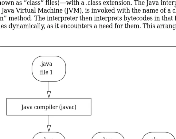
The basic Java architecture consists of two general pieces: a compiler and an interpreter. The Java compiler, “javac,” converts Java source files—with a .java extension—into Java bytecode files (which are known as “class” files)—with a .class extension. The Java interpreter, “java,” also known as the Java Virtual Machine (JVM), is invoked with the name of a class file containing a “main” method. The interpreter then interprets bytecodes in that file, loading additional class files dynamically, as it encounters a need for them. This arrangement is shown in Figure 1.
Figure 1 Java Architecture
Java compiler (javac) .java
file 1
Java interpreter (java)
.class file 2
.class file n ...
The interpreter loads classes dynamically, as it needs them. .class
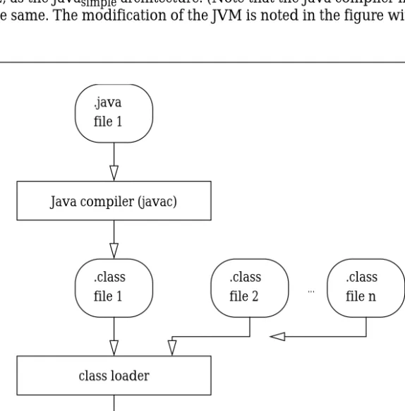
logically between the Java compiler and the modified Java interpreter. This loader gathers all of the necessary class files into one file that we refer to as a “ROM Image File” (RIF). Another simplification is that the JVM does not implement the set of “built-in classes” that are defined in the Java Virtual Machine Specification (e.g., classes for console I/O, networking, and math functions that are not built into the language). We refer to this simplified Java architecture,
shown in Figure 2, as the Javasimple architecture. (Note that the Java compiler in both
architectures is the same. The modification of the JVM is noted in the figure with a trailing apostrophe.)
We implemented our prototype by adding a “Protection Engine” to both the class loader and
the JVM of the Javasimple architecture. The modified class loader applies cryptographic
protection to the bytecodes as it builds an RIF. The modified JVM (a) removes protection as it brings in each bytecode for execution and (b) applies protection when, during execution, it stores on the disk data that it generates. In this way the bytecodes are protected from the time they leave the class loader until the time they are actually executed and the generated data is
Figure 2 Javasimple Architecture
Java compiler (javac) .java
file 1
.class file 1
Java interpreter (java‘)
.class file 2 .class file n ... class loader Rom image file 1
The interpreter does not need to load any class files; the class loader has already done it.
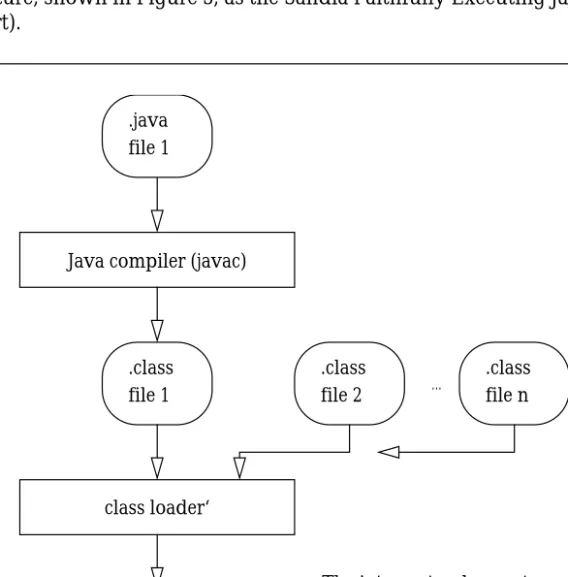
likewise protected while it sits on the disk, thereby providing Faithful Execution. The modified class loader and JVM in concert provide a software implementation of FE. We refer to this
extended architecture, shown in Figure 3, as the Sandia Faithfully Executing JavaFE architecture
(or JavaFE for short).
This report presents a prototype implementation of the JavaFE architecture. The protection
algorithm in the Protection Engine of this initial version of the prototype uses lightweight (yet non-trivial) encryption. The focus of this report is not on the strength of that cryptographic algorithm but on the structure of the implementation. We intend on using the prototype to explore more sophisticated techniques as a step toward implementing those more sophisticated techniques in hardware.
Figure 3 JavaFE Architecture
Java compiler (javac) .java
file 1
.class file 1
Java interpreter (java‘‘)
.class file 2 .class file n ... class loader‘ Rom image file 1
The interpreter does not need to load any .class files; the class loader has already done it.
3 Class Loader
The class loader in the Javasimple architecture is a program that takes one or more class files
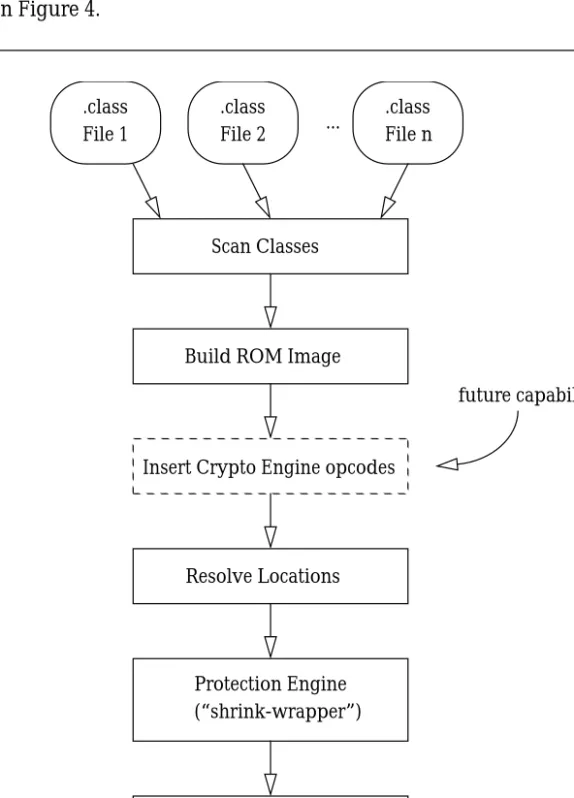
produced by the Java compiler and coalesces them into a single, executable ROM Image File (RIF). When the class loader is invoked it is given the name of the class file that contains the program’s “main” method which is the starting point for execution. The class loader performs a transitive closure on objects referenced by the main method in order to identify all of the class files that need to be included in the RIF. The class loader organizes these files into an
intermediate ROM image representation.
shown explicitly in Figure 4.
One of the reasons we chose the Javasimple architecture as a base was its separate class loader
which would enable us, at loadtime, to insert special “cryptographic opcodes” that would
Figure 4 Class Loader Functions
.class File 1
Scan Classes
Resolve Locations Build ROM Image ...
The shading in the bottom two files denotes privacy protection.
Insert Crypto Engine opcodes
future capability
Write ROM image and KDF Protection Engine (“shrink-wrapper”) .class File 2 .class File n ROM Image KDF
enable us, at runtime, to control the Protection Engine in the JVM. One of these opcodes could provide an initialization vector, for example, to enable synchronization. Another could enable dynamic key changes. This is a future capability of our class loader as depicted by the note adjacent to the “Insert Crypto Engine” step in Figure 4. This step appears before the “Resolve Locations” step because the inserted opcodes would change branch offsets.
After all instruction locations have been resolved our class loader uses its embedded Protection Engine to apply cryptographic protection to the RIF. During this phase the class loader
identifies the boundaries of the code areas and the constant pools for all classes that were collected and it generates unique keys for each. The presence of multiple keys enables switching cryptographic context according to location and memory area. These keys are written to what we refer to as a “Key Definition File” (KDF) (see Section 4.4 and Appendix A.1.3 for details) which in a production system would itself be protected in some way, perhaps encrypted using the public key of the target JVM. The keys in the KDF are used to protect the data in their respective areas using the process presented in Section 4.2 below. This protection process
provides program integrity and is intended to be the software equivalent of “shrink-wrapping.” The protected ROM image contents are written to an RIF, and this file is transferred, along with
4 JVM
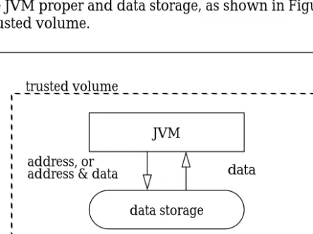
FEConceptually the JVM for the basic Java and Javasimple architectures presented in Section 2
consists of two parts: the JVM proper and data storage, as shown in Figure 5, where the dotted rectangle represents a trusted volume.
The implementation of the JVM for the Javasimple architecture with which we began is itself a
Java class file. The control structure consists primarily of a single loop that, for a specified number of steps, fetches the instruction at the current value of the Program Counter, then executes that instruction, then does another fetch, as shown in pseudocode in Figure 6.
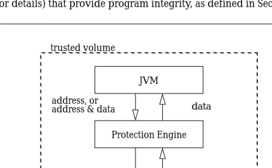
As with our modified class loader, to produce the JVM for the JavaFE architecture we added a
Protection Engine to the JVM in the Javasimple architecture, as shown in Figure 7. The Protection
Engine consists of a set of class files, primarily in the MemoryCell class (see Section 4.2 and
Figure 5 Basic JVM
Figure 6 Main Loop for the JVM for the Javasimple Architecture
address, or
address & data data data storage
trusted volume
JVM
Note: “data storage” includes cache, ram,
secondary storage (disk), network storage, and so on for both instructions and data.
int n = number_of_instructions_to_execute; int pc = 0; // program counter;
for ( int i = 0 ; i < n ; i++ ) {
fetch instruction at current value of pc; execute current instruction;
Appendix A.3.2.9 for details) that provide program integrity, as defined in Section 1.
Note that in Figure 7 “data storage” is outside of the trusted volume, unlike Figure 5. The Protection Engine protects data as the data is pushed out to storage and it removes that protection as the data is pulled back in from storage. The Protection Engine enables data in storage to reside outside of the trusted volume and still be protected. This means that even if an adversary has control of the data as it resides in the cache, in RAM, on the local disk, or on a network disk, the data is still protected. One way of describing FE is as a way to move data storage outside of a trusted volume and still be able to protect that data.
The Protection Engine we have implemented provides byte-level protection and depends on our underlying “translation” scheme, described next.
4.1 Translation
Note: The JVMFEis designed to accommodate protection techniques of arbitrary robustness
and sophistication. Our intention is to use the JVMFE to explore such techniques. As a first
step in that direction we implemented cryptographic techniques, as presented in this sec-tion, that are lightweight (yet non-trivial).
The JVMFE provides program integrity via the addition and removal of protection, as we will
describe in Section 4.2. The approach we describe depends upon a single, Electronic Codebook (ECB) type translation scheme.
The JVMFE has four memory areas—rom, stack, state, and heap—as described in Appendix
A.3.2. For each address in each memory area for which the JVMFE performs either a fetch or a
store we require a set of four keys. Each key is 64 bits. A set of keys can span a range of addresses and can be used for different memory areas. In fact, any permutation of keys,
Figure 7 JVMFE
address, or
address & data data Protection Engine data storage trusted volume protected data JVM plain address, or
addresses, and memory areas can be accommodated.
One key provides sequence integrity, a second provides instruction integrity, a third program privacy (i.e., encryption), and a fourth decryption. The class loader generates the first three of
these keys; the JVMFE derives the fourth from the program privacy key.
We translate an eight-bit byte by independently translating both of its two, 4-bit “nibbles.” We consider each 64-bit key to consist of an array of 16 nibbles indexed from 0 through 15 inclusive. The result of the translation of a nibble is the value of the key array at the index specified by that nibble. So, for example, if a key, represented in hex, is 0x123456789ABCDEF0, and the value of a nibble is 0, then the translation of that nibble using that key is 1, and if the nibble is 1, then the translation is 2, and so on. We have chosen this approach because it is fast, easy to
implement, and economical in that it can be used for each cryptographic step in the application and removal of protection.
We use two types of keys: invertible and non-invertible. An invertible key is a permutation of the hex string 0x0123456789ABCDEF; a non-invertible key is any 16-digit hexadecimal number. The program privacy key must be invertible so that an inverse key can be derived from it. The instruction integrity and sequence integrity keys can be non-invertible. In our prototype we ask that the instruction integrity key be invertible and we allow the sequence integrity key to be non-invertible, the former to get better integrity (see Section 4.2.2) and the latter so that we can increase the keyspace. However, there are valid arguments for other arrangements.
4.2 Protection Algorithms
The Protection Engine of the class loader applies protection to each byte using the first
algorithm described in this section. When the JVMFE performs a fetch, it receives the protected
value from storage, which is outside of the trusted volume, and then, inside of the trusted
volume, the Protection Engine of the JVMFEremoves that protection using the second algorithm
described in this section. When the JVMFE performs a store it first directs the Protection Engine
to apply protection using the same algorithm that the Protection Engine in the class loader uses, then it proceeds to store the protected value on the disk, outside of the trusted volume. The addition and the removal of protection are described diagrammatically below:
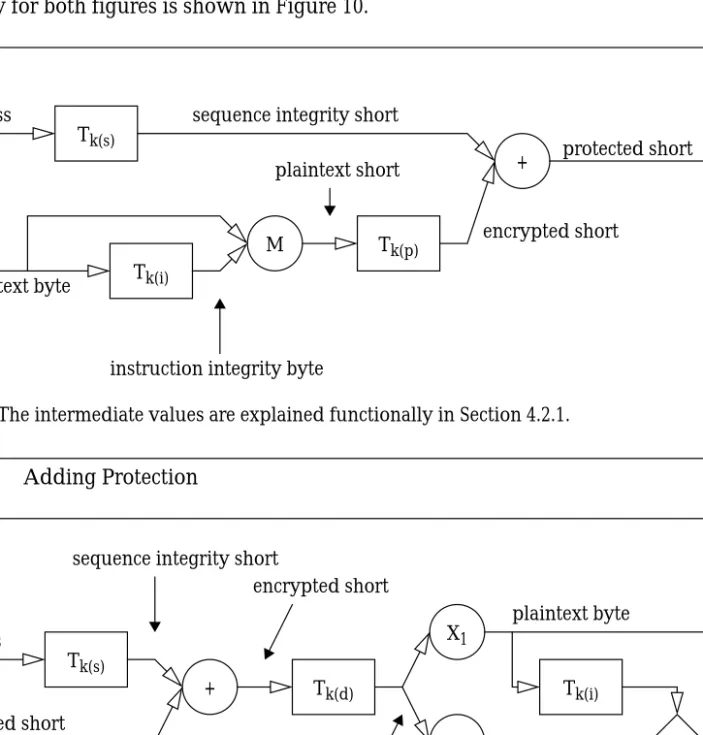
adding protection is shown in Figure 8;
the key for both figures is shown in Figure 10.
Figure 8 Adding Protection
Figure 9 Removing Protection
address
Tk(s)
plaintext byte Tk(i)
M Tk(p)
+ protected short
encrypted short
instruction integrity byte
plaintext short sequence integrity short
Note: The intermediate values are explained functionally in Section 4.2.1.
protected short address
Tk(s)
+ sequence integrity short
Tk(d) Tk(i)
plaintext byte
instruction integrity byte encrypted short plaintext short X1 X2 =? no (integrity fault) (integrity ok) yes
4.2.1 Adding Protection
The protection algorithm for the plaintext byte “b” to be stored at the two-byte address “a” consists of five steps:
1. The JVMFE generates an “instruction integrity byte” by translating (see Section 4.1) the
plaintext byte “b” using the instruction integrity key.
2. The instruction integrity byte from step 1 is combined with the plaintext byte “b” to create a “plaintext short” (a two-byte value).
3. The plaintext short from step 2 is encrypted, i.e., translated using the program privacy (i.e., encryption) key, to create an “encrypted short.”
4. The address “a” where the byte is to be stored, is translated using the sequence integrity key to create a “sequence integrity short.”
5. The sequence integrity short from step 4 is exclusive-or-ed with the encrypted short from step 3 to create a “protected short.”
Let Tk(g)(h) denote the translation of the one- or two-byte value “h” using key g. Let “s” denote
the sequence integrity key, “p” the program privacy (i.e., encryption) key, and “i” the instruction integrity key. Let “M(i,j)” denote the function that mixes or combines its two
parameters (e.g., concatenation). And finally let “⊕” denote the exclusive-or operation. The
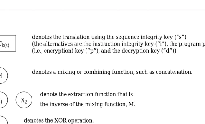
Figure 10 Key for Figure 8 and Figure 9
M Tk(s) + =? X1 X2 Key:
denotes a mixing or combining function, such as concatenation.
denote the extraction function that is the inverse of the mixing function, M. denotes the XOR operation.
denotes the predicate that returns true iff both inputs are identical. denotes the translation using the sequence integrity key (“s”)
(the alternatives are the instruction integrity key (“i”), the program privacy (i.e., encryption) key (“p”), and the decryption key (“d”))
where “c” is the protected short corresponding to plaintext byte “b” to be stored at address “a,” under these particular keys.
4.2.2 Removing Protection
Removing protection is the inverse of adding protection (Equation 1) and consists of two algorithms: decryption (Equation 2) and an integrity check (Equation 3).
The decryption algorithm for the protected short “c” stored at the two-byte address “a” consists of four steps:
1. The address “a” of the protected short “c” is translated (see Section 4.1) using the sequence integrity key to create a sequence integrity short.
2. The sequence integrity short from step 1 is exclusive-or-ed with the protected short “c” to create an encrypted short.
3. The encrypted short from step 2 is decrypted, i.e., translated using the decryption key (i.e., the inverse of the program privacy key), to create a plaintext short.
4. The plaintext byte—as opposed to the instruction integrity byte—of the plaintext short from step 3 is extracted.
Let Tk(g)(h) denote the translation of the one- or two-byte value “h” using key g. Let “s” denote
the sequence key and “d” the decryption key. Let “⊕” denote the exclusive-or operation. And
finally let X denote the extract function that is defined as follows, using the function M, defined
above: for all i and j, i = X1(M(i,j)) and j = X2(M(i,j)). The decryption algorithm can be succinctly
described as follows:
b = X1(Tk(d)(c⊕Tk(s)(a))) (2)
where “b” is the recovered plaintext byte corresponding to the protected short “c” stored at address “a,” under these particular keys.
The integrity check covers both sequence integrity and instruction integrity. The check on instruction integrity is explicit: the instruction integrity byte that is associated and stored with the plaintext byte is compared with an instruction integrity byte that is generated, based on the plaintext byte, just before the comparison is made. The sequence integrity is implicit: if the adversary has moved a protected value to a new address, then the bits that will be fed to the instruction integrity check will be garbled, causing that check to fail.
The integrity check for the protected short “c” stored at the two-byte address “a” consists of seven steps (the first four steps are the same as the decryption algorithm):
1. The address “a” of the protected short “c” is translated (see Section 4.1) using the sequence integrity key to create a sequence integrity short.
2. The sequence integrity short from step 1 is exclusive-or-ed with the protected short “c” to create an encrypted short.
3. The encrypted short from step 2 is decrypted, i.e., translated using the decryption key (i.e., the inverse of the program privacy key), to create a plaintext short.
4. The plaintext byte—as opposed to the instruction integrity byte—of the plaintext short from step 3 is extracted.
5. The instruction integrity byte—as opposed to the plaintext byte—of the plaintext short from step 3 is extracted.
6. The plaintext byte is translated using the instruction integrity key to create an instruction integrity byte.
7. The recovered instruction integrity byte from step 5 is compared with the generated instruc-tion integrity byte from step 6: the plaintext byte has integrity if and only if those two values are the same.
Let Tk(g)(h) denote the translation of the one- or two-byte value “h” using key g. Let “s” denote
the sequence integrity key, “d” the decryption key, and “i” the instruction integrity key. Let “⊕”
denote the exclusive-or operation. And finally let X denote the extract function defined above. The integrity check can be succinctly described as follows:
Tk(i)(b) == X2(Tk(d)(c⊕ Tk(s)(a))) (3)
where “b” is the recovered plaintext byte corresponding to the protected short “c” stored at address “a,” under these particular keys.
4.3 Corruption
In order to simulate an adversary with control of storage the JVMFE enables the user to
“corrupt” (i.e., change) storage contents as the JVMFEexecutes (see Appendix A.1.4 for details).3
When the JVMFEfetches a corrupted value at runtime it raises what we call a “runtime integrity
fault.” A production version of a JVMFE would not have a facility to simulate an adversary, of
course. On the command line the user provides the name of a file, known as a “Corruption Control File” (CCF), each line of which provides the following four items of information:
1. the memory area to be corrupted4;
2. when the corruption is to occur, specified as either a range of the number of bytecodes that have executed or as a range of values of the program counter;
3. the address range of bytes that are to be corrupted; and
4. the value that is to be used to overwrite the current value of the bytes in storage.
During execution of the main loop of the JVMFE the corruption facility is called, as shown in
Figure 11, and it corrupts storage using all of the lines in the corruption file that apply.
As a check on our integrity checking scheme the JVMFE flags each value that is corrupted. If a
runtime integrity fault is not raised when a corrupted value is fetched, the JVMFEannounces the
failure (of our integrity checking scheme) and halts.
CCF to change the stored value and the JVMFE will announce the use of a corrupted value as
that value is fetched but the JVMFE will not interrupt execution (see Appendix A.1 for details).
4.4 Input
The JVMFE is invoked with a “Run Control File” (RCF) that can change default settings for the
run, including possibly the names of the three input files:
•
a ROM Image File (RIF),•
a Key Definition File (KDF), and•
a Corruption Control File (CCF).The RIF is a program file that has been compiled into bytecodes and is usually protected via the
algorithm shown in Section 4.2 and as noted in Section 3. (The JVMFE can execute an
unprotected RIF (see below and also Appendix A.1).) The KDF holds the keys for the RIF. The CCF controls corruption. If the name of a CCF is not provided, no corruption is performed (see Section 4.3).)
The JVMFE checks the integrity of each byte of the RIF as it reads it in to storage, using the keys
supplied by the KDF. This activity takes place during “loadtime.” If an integrity fault occurs at
this time the JVMFE will announce the fault and by default continue (see the
HALT_ON_LOADTIME_INTEGRITY_FAULT parameter in Table 1).
The JVMFE can also accept an unprotected (i.e., a plaintext) RIF which the JVMFE will protect as
it reads it in to storage if a KDF is provided on the command line. If no KDF is provided, the
JVMFEwill not protect such an unprotected RIF and thereafter JVMFEbehaves as though it were
the JVM from the Javasimple architecture.
To enable verification of the behavior of this prototype the JVMFE, at the conclusion of loadtime,
writes zero, one, or two output files. One output file is the plaintext version of the RIF. The second output file, which is generated only if a KDF is provided, is the protected version of the
RIF as it exists in the data storage of the JVMFE.
5. The JVMFE can operate on unprotected storage (see Appendix A.1 for details).
Figure 11 Main Loop for JVMFE, showing the Corruption Facility
int n = number_of_instructions_to_execute; int pc = 0; // program counter;
for ( int i = 0 ; i < n ; i++ ) {
call corrupter, passing it i and pc; fetch instruction at current value of pc; execute current instruction;
5 Status
The modified class loader and JVM have been successfully implemented and were
demonstrated in September, 2002. The JVMFE consists of approximately 7,500 lines of
commented Java code in 16 class files, as opposed to the approximately 2,000 lines of code in
five class files for our version of the JVM for the Javasimple architecture. The protections
algorithms—i.e., the Protection Engine shown in Figure 7—are contained in the MemoryCell class which is approximately 600 lines of code (if comments are removed). The code for both the class loader and the JVM are available, subject to copyright restrictions.
6 Using the Jave
FEThis section describes how to use the class loader and the JVM of the JavaFE architecture to
shrink-wrap and execute Java applications. This section also shows sample output generated
when the JVMFE runs a code that is corrupted during execution.
The first step in using the JVMFE architecture is to write the application that is to be protected.
The JVMsimpledoes not implement the set of “built-in classes,” as noted in Section 4, and the
JVMFE does not expand on that set. So the set of applications that can run on the JVMFE is
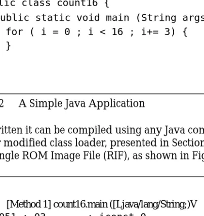
currently limited to those that do not make calls to those built-in classes. An example of a simple application is shown in Figure 12.
Once the Java source is written it can be compiled using any Java compiler to develop one or more class files. Using our modified class loader, presented in Section 3, these class files should then be coalesced into a single ROM Image File (RIF), as shown in Figure 13.
Figure 12 A Simple Java Application
Figure 13 RIF for Figure 12
public class count16 {
public static void main (String args[]) {
} }
for ( i = 0 ; i < 16 ; i+= 3) {
}
[Method 1] count16.main ([Ljava/lang/String;)V
0051 : 03 : iconst_0 0052 : 3d : istore_2 0053 : 03 : iconst_0 0054 : 3c : istore_1
0055 : a7 00 03 : goto 3 //005bH
0058 : 84 01 01 : iinc stack index(1)1 005b : 1b : iload_1
005c : 10 10 : bipush 16
005e : a1 ff f7 : if_icmplt -9// 0058H 0061 : b1 : return
used to protect the other areas of memory (see Appendix A.3.2 for details).) The protected RIF
and then KDF can then be fed to a JVMFE.
When the JVMFE begins execution it first opens the KDF and loads the keys found in that file.
The JVMFE then loads the protected ROM image in to data storage, checking the integrity of
each protected value as the value is read in. The JVMFE also accepts a CCF that enables the user
to model an adversary who can change bits in storage during execution (see Section 4.3 for details).
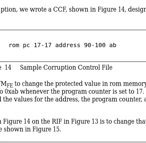
As an example of corruption, we wrote a CCF, shown in Figure 14, designed to corrupt the code in Figure 12.
This CCF directs the JVMFE to change the protected value in rom memory at byte address 90
through 100 inclusive to 0xab whenever the program counter is set to 17. (For this example we empirically determined the values for the address, the program counter, and the corruption value.)
The effect of the CCF in Figure 14 on the RIF in Figure 13 is to change that RIF to one that corresponds to the code shown in Figure 15.
The arrow in Figure 15 points out the difference between the code in Figure 12 and the code in Figure 15: the loop increment in Figure 12 is 1, but the loop increment in Figure 15 is 3.
Figure 16 shows the RIF that corresponds to Figure 15. The arrow points out the difference
Figure 14 Sample Corruption Control File
Figure 15 Modified Code from Figure 12
rom pc 17-17 address 90-100 ab
public class count16 {
public static void main (String args[]) {
} }
for ( i = 0 ; i < 16 ; i+= 3) {
between this RIF and the one shown in Figure 13.
When the JVMFE executes the RIF shown in Figure 13 it checks each time through the main
loop, as shown in Figure 11 on page 26, to see if corruption should be done. When the program
counter is set to 17 the protected value at decimal address 90 (hex 5A) is changed, as the JVMFE
announces in the upper half of Figure 17.6When the JVMFEsubsequently fetches that corrupted
protected value at decimal byte address 90 it announces an integrity fault, then halts, as shown in the lower half of Figure 17. (Note that Figure 17 is showing protected values, not plaintext values. That is, 0x77 is the protected value at the given address with the given keys for the value
Figure 16 RIF for Figure 15
[Method 1] count16.main ([Ljava/lang/String;)V
0051 : 03 : iconst_0 0052 : 3d : istore_2 0053 : 03 : iconst_0 0054 : 3c : istore_1
0055 : a7 00 03 : goto 3 //005bH
0058 : 84 01 03 : iinc stack index(1)1 005b : 1b : iload_1
005c : 10 10 : bipush 16
005e : a1 ff f7 : if_icmplt -9// 0058H 0061 : b1 : return
1, and 0xab is the protected value at the given address with the given keys for the value 3.)
Figure 17 Detection of Integrity Fault
Execution of code begins.
MemoryCell (rom): byte address 90 (0x5A): corruption:
original value: 0x77 corrupted value: 0xab
Fatal error:
MemoryCell (rom) byte address 90 (0x5A):
runtime integrity fault; (corrupted value);
(no integrity fault when reading rom file); (no integrity fault when writing rom file);
7 Conclusion
In this report we have presented the implementation of a stateless scheme for FE, the design for which is presented in a companion report. We described the architectural basis for the
prototype, the changes we applied to provide protection, the nature of that protection, and a “corruption” facility. We have shown sample input and output of the running prototype. The Appendix which follows the body of this report provides additional details.
Appendix A Additional Details of the JVM
FE
This Appendix provides details on aspects of the JVMFE that play a supporting role to the
material provided in the body of this report.
The details of the various objects in the JVMFE and their relationship to each other are described
later in this Appendix. Unfortunately such understanding is presumed in this introductory material. Consequently, if the details of this introductory material are confusing, the reader is encouraged to skip ahead, and then to return after digesting the rest of the Appendix.
This report describes a prototype, not a production system. The most important aspect of the prototype is the modularity it provides for the “MemoryCell” class that does the protection. The API for this class has only three methods:
•
a constructor to store a byte, and•
two other methods to get a plaintext byte or get a protected value.7MemoryCell is controlled by only one class (Memory), and it has a reference to only one class (KeySet). The simplicity of this design will facilitate experimenting with different protection approaches: all that is required to try a different approach is to change MemoryCell. (If the names, number or nature of the keys change, then KeyChain and Keyset would also need to be changed.)
Since the JVMFE is a prototype designed to experiment with different protection approaches a
main design goal of the JVMFE is to confirm the operation of those approaches. As a result, the
JVMFE is neither efficient nor (in and of itself) secure. Both of these design aspects would be
taken care of in a production version.
The JVMFE is not efficient due to the following features:
1. The JVMFE creates a new MemoryCell object each time it stores a byte. This approach
removes problems due to data leftover from a previous store.
2. Each time through the main interpretive loop (i.e., each time a bytecode executes), methods are called to check to see if an attacker should be simulated. This simulated attacker can change any bits any number of times while instructions or data are on the disk during exe-cution.
3. The memory hierarchy opts for method re-use rather than efficiency. For example, the MemoryBase class implements the getTwoBytes method by returning the concatenation of two calls to its getOneByte method.
4. The debugging facilities integrated into the JVMFE(see the VIEW parameters in Table 1) use
IF statements, the predicates for which are executed even if the debugging facilities are turned off. It would be more efficient to use the Java equivalent of IFDEF statements as in C that can be temporarily removed in a compiler preprocessing step.
1. The Memory class retains each byte, in plaintext, as it is stored in a MemoryCell object.8 This is done to confirm the operation of MemoryCell.
2. MemoryCell, like Memory, retains each byte, in plaintext, as it protects that byte. This is done to confirm its own operation. MemoryCell also retains all intermediate values gener-ated in the process of protecting. And again, this is done to confirm MemoryCell’s opera-tion.
3. The plaintext equivalent of the input protected value given to the JVMFE is written to a file
at the beginning of execution in order to confirm that the protected value corresponds to the plaintext previously given to the class loader.
The remainder of this Appendix is organized as follows. In Appendix A.1 we show the input to
the JVMFE, including how to run it. In Appendix A.2 we show sample output of the JVMFE.
And in Appendix A.3 we present the class hierarchy of the JVM for both the Javasimpleand the
JVMFE architectures.
Note: In this Appendix “JVMFE” refers to all of the code constituting the JVMFE. When we
are discussing the Java class named “JVMFE.java” (see Appendix A.3) we use the name “JVMFE” (e.g., see NUMBER_OF_STEPS_TO_EXECUTE in Table 1).
8. The following is a detail that can be safely ignored by the reader but is included here for completeness: If the JVMFEis given a pro-tected RIF (the presumed, normal occurrence), then Memory directs MemoryCell to provide it (Memory) with the plain text corre-sponding to each protected value that Memory gives to MemoryCell to be stored. In this way Memory is still able to retain a plaintext byte for each byte given to MemoryCell, even though the ROM Image File is protected.
A.1 JVM
FEInput
The JVMFE uses four input files:
1. a Run Control File (RCF) —required
2. a ROM Image File (RIF) —required
3. a Key Definition File (KDF) —optional
4. a Corruption Control File (CCF) —optional
Each of these are presented in turn below.
A.1.1 Run Control File (RCF)
The Run Control File (RCF) changes parameters for an invocation of the JVMFE. The JVMFE will use the RCF specified on the command line, or, if none is specified, it will use the default RCF. If there is no default RCF, JVMFE will write one, then halt, as shown below.
There are two forms of the command line for the JVMFE:
java JVMFE and
java JVMFE rcfn where
rcfn is replaced by a run control filename (RCF).
The first form of the command line will use the default RCF, and the second form will use the
RCF given on the command line. In either case, if the RCF file does not exist, then the JVMFE
will (a) write a copy of the default RCF (if the default RCF does not exist), and (b) print the following information before it halts:
Execution begins.
Writing default run control file to file: run.rcf Usage:
java JVMFE --Use the default run control file: ’run.rcf’.
If that file does not exist, then we write out a fresh one.
(We just wrote out a fresh one.) java JVMFE <run control filename>
The collection of parameters specified in the RCF coalesce into four groups: 1. file specification;
2. run control; 3. key control; and 4. view control.
The parameters and their defaults are shown in Table 1. (The Table presumes familiarity with
the classes that constitute the JVMFE, all of which are presented in Appendix A.3. The
parameters in Table 1 that contain the name of a class of the JVMFE use the standard Java
naming convention for classes, namely, the first letter is capitalized and the first letter of each subsequent word is capitalized. Thus, for example, “VIEW_MemoryIntegerAddressable” refers to the MemoryIntegerAddressable class.) Following the Table are shown sample RCFs.
Table 1 Run Command File parameters (Sheet 1 of 7)
Name Meaning or Action
File Specification
RIF_FILENAME This is the name of the ROM Image File (RIF). Default: rif_file.rif
KDF_FILENAME
This is the name of a Key Definition File. If this parameter is set to “none” or “-”, then no protec-tion occurs, and if RIF_PROTECTED is also set to true (see below), then the JVMFE will halt: the JVMFE cannot execute a protected
RIF_FILENAME if the JVMFE does not have a KDF.
Default: kdf_file.kdf
CCF_FILENAME
This is the name of a Corruption Control File. If this is set to “none” or “-”, then no corruption occurs.
Default: ccf_file.ccf
RIF_PROTECTED
If this parameter is true, then the
RIF_FILENAME is assumed to be protected. Oth-erwise the ROM _FILENAME is presumed to be in cleartext.
Default: true. Run Control
NUMBER_OF_STEPS_TO_EXECUTE
This parameter holds the number of times through the main loop that the JVMFE will pro-ceed. The loader arranges the RIF so that after the useful work is done the JVMFE executes a tight loop: it executes a bytecode that is a GOTO to the address of that same bytecode.
Default: 8000 (the default in the JVM in the Jav-asimple architecture); range of possible values 0…10000.
HALT_ON_LOADTIME_INTEGRITY_FAULT
If this parameter is set to true (and a KDF file has been supplied (see above)), then the JVMFE halts on an integrity fault at loadtime. This would only occur when the JVMFE is reading in the RIF (via ReadRom) or when rom storage is being written out (via WriteRom), both of which occur only at loadtime. (The rom storage is written out as a debugging aid.)
(Note: The JVMFE always announces integrity faults at both loadtime and runtime but does not always halt. For example, if a KDF file has not been supplied, then there is nothing against which the JVMFE can use to check the integrity. (See Table 2 on page 45.))
Default: false.
HALT_ON_RUNTIME_INTEGRITY_FAULT
If this parameter is set to true (and a KDF file has been supplied (see above)), then the JVMFE halts on an integrity fault at runtime.
The JVMFEalways halt on a corrupted, protected value that does not raise an integrity fault. (See table cell immediately above.) Default: true.
HALT_ON_ANY_RUNTIME_ UNPROTECTION_ERROR
If this parameter is set to true (and a KDF file has been supplied (see above)), then JVMFE halts on any runtime error in the removal of protection, even if
HALT_ON_RUNTIME_INTEGRITY_FAULT is false (see above). The JVMFE could halt on a mis-match between the intermediate values gener-ated when the byte was stored, for example, or the JVMFE could halt because the plaintext byte that is being returned does not match the plain-text byte that was given to be stored, as recorded in the MemoryCell class. These latter problems are not integrity faults but rather faults with our algorithm or in our implementation.
MemoryCell uses this parameter as its last step in fetching a byte, after checking integrity.
Default: true.
Table 1 Run Command File parameters (Sheet 2 of 7)
HALT_ON_BAD_FETCH
If this parameter is set to true (and a KDF file has been supplied (see above)), then the JVMFE halts whenever either of the following is true:
(a) there is no previously-stored data at the address specified by a fetch (this can happen either because there has been no store to the address since execution began or because there has been no store since the last clear command), or
(b) the byte to be returned does not match the byte previously stored.
Note that this check is performed in the Memory class and is thus independent of the MemoryCell class. This check represents a final opportunity to confirm that the memory hierarchy is returning the correct value. A user might want to turn this feature off in order to see the effect on the JVMFE of corruption of a plaintext file.
Default: true.
CHECK_DERIVEDBYTE
If this parameter is set to true (and a KDF file has been supplied (see above)), then the JVMFEhalts, when given a plaintext byte to store, if the plain-text byte that would be returned if it were to be fetched immediately does not match the plaintext byte just given.
This parameter implements a check, at the time of the store, of our internal protection process. The overhead required for this check can be valuable for two reasons:
(1) an error, when raised, is associated with the store that caused it, rather an unrelated fetch; and (2) this check enables a check of all stores, not just those stores for which there is a subsequent fetch. (There is always a check on a fetch.)
Default: true.
Table 1 Run Command File parameters (Sheet 3 of 7)
CHECK_MemoryCell_ CANDIDATE_VALUE
If this parameter is set to true, then the JVMFE halts if there is extra (i.e., non-zero) data in the input to a store operation.
The parameter to a store operation is always an int (4 bytes). If the value is protected, as it will be when the JVMFE is loading a protected RIF, then the left two bytes of the input int should be zeros. If the value is plaintext, as it will be at all other times, then the left three bytes should be zeros. The overhead required for this check can be valu-able to confirm that the input to MemoryCell is proper. If there happen to be extra byte(s), they will not cause a problem in and of themselves— they are ignored. However, the presence of extra byte(s) indicates a semantic problem prior to MemoryCell’s invocation: some method may be trying to store more bytes than MemoryCell is actually storing.
Default: true.
WRITE_PLAINTEXT_ROM
If this parameter is true, then at loadtime the JVMFEwrites out the plaintext equivalent of what it loaded in to memory. If what was loaded was protected, the JVMFE removes that protection as it writes it to the file.
The name of this file is <RIF>.plain. where <RIF> is the name of the RIF.
This feature is a debugging aid to enable confir-mation that what the JVMFE loaded is what was given to the class loader. A production version of the JVMFE would not provide this feature. Default: true.
WRITE_PROTECTED_ROM
If this parameter is true, then the JVMFE writes out the protected equivalent of what it loaded in to memory. If what was loaded was plaintext and a KDF is not available (see above), then JVMFE is unable to write out protected values.
The name of this file is <RIF>.protected. where <RIF> is the name of the RIF.
This feature is a debugging aid to enable confir-mation of what the JVMFE loaded.
Default: true.
Table 1 Run Command File parameters (Sheet 4 of 7)
Key Control
MAX_VALUE_INDEX_MATCHES_IN_KEY
The JVMFE halts if the number of “index
matches” (defined in the next paragraph) exceeds the value of this field for any key.
Definition of “index match:” Given that each key is converted internally into an array with indices from 0 through 15 inclusive, and given that the value of each such array element is constrained to the same range, 0 through 15 inclusive, then an “index match” exists when, for some value i, 0≤i
≤ 15, the value of array element i is i.
This constraint is a measure of the strength of a key within our protection algorithm and causes the JVMFE to reject certain “weak keys.” Default: 4 (possible values 0…16).
MIN_VALUES_IN_KEY
The JVMFE halts if any non-invertible key uses fewer unique values than the value of this field. For example, the key 0x1234123412341234 uses only four unique values—1, 2, 3, and 4.
Invertible keys always use all 16 possible values but non-invertible keys can use less than 16 val-ues.
This feature causes the JVMFE to reject certain “weak keys.”
Default: 4 (possible values 1…16).
ADD_LAST_CHANCE_BLANKET_KEY
If this key is true, then the KeyChain class adds an additional key that covers or “blankets” the rest of memory (for non-rom memory only). Default: true.
Table 1 Run Command File parameters (Sheet 5 of 7)
View Control
For each of the parameters below, if set to true, then the corresponding class (e.g., the class corre-sponding to “VIEW_JVMFE” is JVMFE) will generate output about its activity as it executes. (See Appendix A.3 for details on JVMFE classes.)
VIEW_ALL
This parameter overrides the settings for all of the other VIEW parameters, regardless of their default values or the settings in the Run Control File:
If this parameter is set to “yes”, then all VIEW parameters are set to true.
If this parameter is set to “no”, then all VIEW parameters are set to false.
If this parameter is set to “neither”, then this parameter has no effect.
Default: neither (possible values “yes”, “no”, and “neither”).
VIEW_JVMFE
Announce the creation of each memory area, the initialization of variables, the beginning of runt-ime, and, each time through the main loop, the step (the number of bytecodes that have been executed), the value of the pc, and the bytecode to be executed.
Default: true.
VIEW_MemoryIntegerAddressable As each method in the class is invoked announce the name of the method, the address that is given, and the data that is being stored or fetched, as appropriate. Default: false. VIEW_MemoryByteAddressable VIEW_MemoryBasea VIEW_MemoryControllerb VIEW_Memory
Announce the settings of all the fields (upon cre-ation), each translated address, the address and value of each store, the address of each fetch and what is returned, and the address of each clear command.
Default: false.
VIEW_MemoryCell
Announce the settings of all the fields (upon cre-ation), each translated address, the address of each fetch, and the translation of each nibble. (Viewing corruption is turned on/off via the VIEW_CORRUPTION_ACTIVITY parameter (see below).)
Default: false.
Table 1 Run Command File parameters (Sheet 6 of 7)
The behavior of the JVMFE hinges on the presence/absence of the name of a Key Definition File
(KDF). If the name of a KDF is given, then the JVMFE provides protection for data while the
data is outside of the trusted volume. If, on the other hand, the name of a KDF is absent, then
the JVMFE behaves like the JVM for the Javasimplearchitecture: it provides no protection. This
behavior is complicated by the RIF_PROTECTED parameter and is most succinctly described via a table, as we have provided in Table 2.
VIEW_KeyChain
Announce the name of the KDF being used and each line as it is read in (noting those lines that do not apply), and the addition of the last-chance-blanket key (if appropriate).
Default: false. VIEW_KeySet
Announce all of the fields of the key set (upon creation).
Default: false.
VIEW_CorruptionChain
Announce the name of the CCF being used and each line as it is read in (noting those lines that do not apply).
Default: true. VIEW_CorruptionSet
Announce all of the fields of the corruption set (upon creation).
Default: false.
VIEW_CORRUPTION_ACTIVITY
Announce, for each value that is corrupted, the original value, the previously corrupted value (if appropriate), and the new (corrupted) value, and if the corruption just happens to restore the value to its original value.
(This activity takes place in MemoryCell.) Default: true.
VIEW_ReadRom
Announce each input line as it is read in. (The name of the RIF that is read in is always announced.)
Default: false.
VIEW_WriteRom
Announce each output line as it is written. (The name of the RIF that is read in is always
announced.) Default: false. VIEW_Helper
Announce the input and the output of each method in this class as it is invoked. Default: false.
a. If this parameter is set to true, the VIEW_MemoryIntegerAddressable and VIEW_MemoryByteAddressable parameters should probably also be set to true (see Figure 20 on page 59).
b. If this parameter is set to true, then the VIEW_MemoryBase should probably also be set to true (see Figure 20 on page 59).
Table 1 Run Command File parameters (Sheet 7 of 7)
Corruption can be applied to a plaintext file. During such an execution the JVMFE is, with
almost certain probability, fed illegal bytecodes and bad data. The JVMFE will announce each
corrupted byte as it is fetched but it does nothing to preclude unpredictable execution unless the HALT_ON_BAD_FETCH parameter is set to true (see Table 1).
We present below several example Run Command Files, followed by an explanation of the
action that the JVMFE takes as a result. Each RCF uses the default settings for the parameters
that are not listed in the RCF. Note that the parameter names are case-sensitive. Example 0:
RIF_FILENAME = myrom KDF_FILENAME = keyfile
CCF_FILENAME = corruptionfile RIF_PROTECTED = true
Execute RIF “myrom,” which is declared to be protected (because RIF_PROTECTED is set to true, which happens to be the default setting), for the default number of steps, using “key-file” as the KDF and “corruption“key-file” as the CCF.
Example 1:
RIF_FILENAME = myrom
// note that either “none” or “-” can be used to // indicate the absence of a file:
KDF_FILENAME = none CCF_FILENAME = -RIF_PROTECTED = false
NUMBER_OF_STEPS_TO_EXECUTE = 10
Execute RIF “myrom,” which is declared to be unprotected (i.e., in plaintext), for 10 steps; no
protection or corruption is done. Executing plaintext enables comparing the JVMFEwith the
JVM for the Javasimple architecture.
Table 2 Protecting Memory
Is a KDF given? Is RIF_PROTECTED?
JVMFE Action
Loadtime Runtime
Yes
Yes Check integrity as the
RIF is read in. Protect all memory areas.
No Apply protection to the RIF as it is read in.
No
Yes Halt: a protected RIF is useless without a KDF. No
Behave like the JVM for the Javasimple architec-ture: do not protect instructions or data while they are outside of the trusted volume.
CCF_FILENAME = -RIF_PROTECTED = false
NUMBER_OF_STEPS_TO_EXECUTE = 10
Execute RIF “myrom,” which is declared to be unprotected, for the default number of steps, using “keyfile” as the KDF; no corruption is done. The RIF is protected as it is read into memory.
Example 3:
// note that the order of parameters in the file is unimportant; RIF_PROTECTED = false
RIF_FILENAME = myrom KDF_FILENAME = none
CCF_FILENAME = corruptionfile HALT_ON_BAD_FETCH = false
Execute RIF “myrom,” which is declared to be unprotected, for the default number of steps,
using “corruptionfile” as the CCF; no protection is done. Also, the JVMFE is instructed to
ignore fetches that return a value that is different than the byte that was last stored at the given address (and also ignore whatever returns even if there is no previous store). Example 4:
RIF_FILENAME = myrom KDF_FILENAME = none
CCF_FILENAME = corruptionfile RIF_PROTECTED = true
When given this run control file, the JVMFE halts after announcing that it is not possible for
it to execute a protected RIF without the name of a KDF.
A.1.2 ROM Image File (RIF)
The ROM Image File (RIF) is an ASCII file.
If the RIF is protected, then the format is assumed to be two shorts (16 bits each, for 32 bits total), in binary, per input line, where each bit is represented by either the character “0” or the character “1.”
If the RIF is unprotected text, then the format is assumed to be two bytes (8 bits each, for 16 bits total), in binary, per input line, where each bit is represented by either the character “0” or the character “1.”
(The syntax of the RIF is outside of the scope of this report.)
A.1.3 Key Definition File (KDF)
Protection is turned on only when the name of a KDF is provided in the RCF (see Appendix A.1.1). Each line of a KDF defines a set of keys and is referred to as a “key set.”
A KDF is an ASCII file that consists of one or more lines, the syntax for which is shown in a simplified BNF below:
S :== MA [MT] RANGE AK UK EK
MA :== “rom” | “heap” | “stack” | “state” MT :== “I” | “C” --if and only if MA is “rom” RANGE :== { START STOP | START “*” | “*” }
START, STOP :== <a non-negative integer, in decimal> IK, SK, PK :== <a long, in hex>
where
the input line is both blank- and dash-delimited; in the BNF above it is shown as blank-delimited but you can use a dash instead of a space to separate items; you might want to do this between START and STOP, for example, to make the sense of range clear; non-terminals are shown in uppercase, unquoted;
terminals are shown either as quoted strings or via their format, in which case they are shown within angle brackets (“<>”); square brackets (“[]”) identify optional items;
the vertical stroke (“|”) separates items in a selection (exactly one in the selection is to be chosen);
comments in the BNF begin with “--” and extend to the end of the line;
S is the start symbol; MA denotes a memory area; MT denotes a memory type;
I denotes the instruction area of rom memory; C denotes the constants area rom memory; RANGE denote a range of memory addresses;
* is a wildcard that denotes the rest of a range; if used alone, it denotes all of a range;
START denotes the beginning of a range; STOP denotes the inclusive end of a range; IK denotes an instruction integrity key; SK denotes an sequence integrity key; and
PK denotes an program privacy key (which serves as the encryption key).
If MA is “rom”, then MT must be present and denotes whether the memory area contains instruction (“I”) or constants (“C”); otherwise MT must be absent.
START must be≥0 and < sizeInBytes, where sizeInBytes is the number of bytes allocated for the
memory area. In addition, START must be≤ STOP unless STOP is “*”.
If multiple key sets specify the same address for the same memory area, then the first set to
appear in the KDF is used.9
If there are “holes” (i.e., addresses (a) for which there are no keys and (b) that are between 0 and
the last address for which there is a key) in a set of KeySets, then the JVMFE takes no notice of
them unless it tries to store to or fetch from that hole, whereupon the JVMFE halts, complaining
of a missing keyset.
Comments lines in the KDF begin with “//”.
Fragments of several KDFs follow (the columns do not need to be aligned as they are shown in these examples).
Example 0:
rom C 0 31 c395ea862bfd714e b15c4d270693ea8f 1e354abc20879fd6 rom I 32 47 f748a2d69b1e3c5d a89125fd746e3cbf d8fb60a5913c274e rom I 64 115 524fd07b1e38c9a6 a5b06d2ef741c389 c684d1a29f05be37 rom C 116 139 83c75f0aed62b914 f3e2b7c408156a9d 8256b01c943ade7f rom C 48 63 b305caf7d16284e9 df820c53a6eb4791 1e5d9a8732cb0f46 Note that the addresses do not need to be sorted.
Example 1:
stack 0-200 f748a2d69b1e3c5d a89125fd746e3cbf d8fb60a5913c274e state 0-100 b305caf7d16284e9 df820c53a6eb4791 1e5d9a8732cb0f46 state 101 * 83c75f0aed62b914 f3e2b7c408156a9d 8256b01c943ade7f heap * 524fd07b1e38c9a6 a5b06d2ef741c389 c684d1a29f05be37 This KDF specifies one set of keys for the first 200 addresses of stack memory, two sets of keys for all of state memory, and one set of keys for all of heap memory.
The only place in the JVMFE where any keys are used is in the “translation” process (in
MemoryCell), described in Section 4.1, which underlies the protection process, described in Section 4.2 (see also Appendix A.3).
A.1.4 Corruption Control File (CCF)
The Corruption Control File (CCF) contains the information required to operate the
“corruption” facility, the purpose of which is to simulate an attacker that changes bits of the RIF
or other areas of memory during execution. Recall that memory in the JVMFE is outside of the
trusted volume and is thus subject to attack. The corruption facility enables the simulation of
9. The KeyChain class puts new KeySet objects at the end of the list when it reads the KDF. And when KeyChain searches the list for a matching KeySet, it starts at the front of the list. So the first matching KeySet is the one that is used. A subsequent match is not found.
such attacks.
Corruption is turned on only when the name of a CCF is provided in the RCF (see Appendix A.1.1). Each line of a CCF is referred to as a “corruption set.” Corruption occurs either when the
JVMFEhas executed a certain number of steps or when the program counter is at a certain value
(or both).
A CCF is an ASCII file that consists of one or more lines, the syntax for which is shown in a simplified BNF below:
S :== MA { “step” | “pc” } RANGE “address” RANGE VALUE MA :== “rom” | “heap” | “stack” | “state”
RANGE :== { START STOP | START “*” | “*” }
START, STOP :== <a non-negative integer value, in decimal> VALUE :== <a 16-bit value, in hex>
where
the input line is both blank- and dash-delimited; in the BNF above it is shown as blank-delimited but you can use a dash instead of a space to separate items; you might want to do this between START and STOP, for example, to make the sense of range clear; non-terminals are shown in uppercase, unquoted;
terminals are shown either as quoted strings or via their format, in which case they are shown within angle brackets (“<>”); the vertical stroke (“|”) separates items in a selection (exactly
one in the selection is to be chosen); S is the start symbol;
MA denotes a memory area;
RANGE denote a range of values;
* is a wildcard that denotes the rest of a range; if used alone, it denotes all of a range;
START denotes the beginning of a range;
STOP denotes the inclusive end of a range; and VALUE denotes a corruption value.
The first RANGE is associated with the “step” or “pc” (for ease of reference we call this the “step/pc range”); the second range specifies the byte addresses that are to be corrupted (we call this the “address range”). The “address” keyword is not necessary to unambiguously parse; it is included as a visual separator.
If “step” is specified, then the step/pc range must be within the range of possible steps that the JVMFE will execute (see NUMBER_OF_STEPS_TO_EXECUTE in Table 1).
If “pc” is specified, then the step/pc range must be within the range of values that the program counter can assume. The lower bound on this range is 0. The upper bound on this range