Operating Network Load Balancing with the Media Independent Information
Service for Vehicular Based Systems
Chi Ma, Enda Fallon, Yuansong Qiao, Brian Lee
Software Research Institute Athlone Institute of Technology
Athlone, Ireland {cma,efallon,ysqiao, blee}@ait.ie
Abstract— A mechanism is designed here to realize Network_Load_Balancing (NLB) by directing handover based on Media
Independent Handover for vehicular based systems. We designed a Predictive_Link_Going_Down event based on Media Independent Event Service which accurately estimates the performance degradation to predict vehicle movements and a Predictive_Handover_Information_Structure (PHIS) based on Media Independent Information Service. This includes the network geographical information, MN’s moving information and network loading situation. PHIS is sent to upper layer mobility protocol dynamically as input for NLB operation, which utilizes a MN direction fuzzy logic to consider both the vehicle movement prediction and current network loading situation and Optimal Candidate Base Station Selection, which utilizes the fuzzy MADM algorithm. Results illustrate the proposed approach reduces more than 95% handover duration in comparison to without utilizing any link triggers. With the NLB operation, delay is reduced by 1ms and jitter is nearly closed to 0, thus significantly improving QoS.
Keywords- MIH, IEEE 802.21, Handover, Fuzzy MADM, Network Load Balancing
I. INTRODUCTION
For some time wireless networking technologies have been developing rapidly. The introduction of cellular technologies such as Third Generation networks (3G) together with its variants HSDPA, HSUPA and HSPA+ have enhanced the underlying capability of traditional telecommunications networks. In the area of wireless networks the introduction of 802.11n and 802.16e has enhanced the range and flexibility of wireless networks. Coupled with the increased capability in underlying networks, smart end user devices have attracted significant consumer interest. Many cellular devices are now designed to support Wi-Fi, Bluetooth, and 3G interfaces. Moreover, many laptops are shipped with standard support for Ethernet, Wi-Fi, WiMAX, Bluetooth, Wireless Infrared, 3G, etc. Underpinned by technical advances in underlying networks and coupled with increased consumer demand for smart devices have resulted in a necessity to support seamless handover in heterogeneous networks.
Media Independent Handover (MIH) is a draft standard under development by IEEE 802.21 [1] working group which proposes to optimize handovers between heterogeneous IEEE 802 systems and between IEEE 802 systems and cellular systems. MIH defines a set of tools to exchange information, events and commands to facilitate handover.
In this paper, we propose a model to improve the handover performance of the existing MIH implementation. Our approach introduces the following components:
a predictive handover trigger event – PLGD event
an algorithm to select best candidate BS for handover based on fuzzy MADM which takes a PHIS element from PLGD event as input
an algorithm of realizing NLB using MIIS for vehicular based systems.
In the proposed scheme, a new PLGD event which utilizes the estimated time of network failure provided by the mathematical model is designed. By accurately estimating the time of network failure the PLGD event can be triggered providing the Upper Layer Mobility Protocol (ULMP) with sufficient time to initiate the handover process prior to actual network failure. We also define a PHIS in order to communicate the required information to ULMP to implement Optimal Candidate Base Station Selection/Network Load Balancing (OCBSS/NLB).
In the second part, a network selection algorithm is proposed based on fuzzy MADA which takes the PHIS element as input. PHIS element includes the MN’s current movement patterns, dynamic network performance metrics and neighborhood information.
Finally a new NLB algorithm which utilized PLGD event and PHIS element to achieve network resource optimization is proposed. Utilizing the PHIS element, the NLB operation is realized by directing the handover based on the MN’s movement, BS geographical information and current network load.
Finally we use handover to realize NLB. The MNs are allocated by considering both the BSs’ load situation as well as the MNs’ movement. All of the information such as the BSs’ location, BSs’ coverage, BSs’ load situation, MNs’
moving information and other required network information are received from the MIIS.
Several simulated scenarios are undertaken which utilize NS2 [2] together with the WiMAX mobility package from NIST [3]. Simulated results presented illustrate the proposed model improves handover performance and significantly improves QoS. In particular our results illustrate that the propose approach achieves effective network load balancing.
This paper is organized as follows: related work is described in Section II. An MIH background is introduced in Section III. Our proposed model is explained in Section IV. In Section V the experiment environment is described together with a detailed analysis of the simulation results. Finally conclusions are presented in Section VI.
II. RELATED WORKS
A. Handover Algorithm
Various studies have investigated algorithms to improve handover performance for heterogeneous networks. [11] proposed a mobility-based prediction algorithm with dynamic LGD triggering for vertical handover by applying the Media Independent Information Service (MIIS). The approach can advance the LGD trigger point dynamically to predictably prepare for the handover using the Possible Moving Area to indicate a next target cell. [9] proposes a novel architecture called Seamless Wireless internet for Fast Trains (SWiFT). SWiFT relies on a fast handoff mechanism and L2 triggering using a handover probability value evaluated by high speed movement and RSS to decide handoff.
Existing handover mechanisms are designed based on a pre-defined threshold (thlgd) in order to trigger the LGD
event in MIH. Many of these mechanisms use RSS as the source performance metric on which thlgd is applied as shown
in Figure 1. The LGD event is triggered to initiate the handover process when the value of recorded RSS crosses the value of thlgd. (1) is used to calculated thlgd.
thlgd lgdthlgd
Figure 1 Pre-defined Thresholds LGD Event
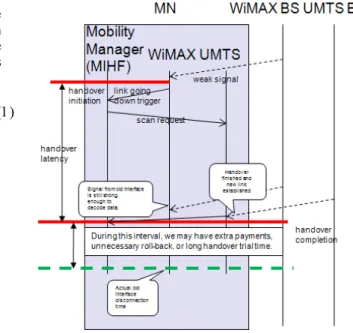
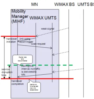
Such an event trigger mechanism is performance limited as neither the user’s dynamic movement information nor the required time to prepare for handover are considered. A premature or delayed handover as shown in Figure 2 and Figure 3 will result in an incorrect thlgd value, resulting in
reduced end user perceived QoS and poor network utilization.
Some new predictive handover mechanisms were proposed in [4] [7] and [8], which used the network neighbourhood information in MIIS to prepare for the impending handover before failure of the underlying network path. An enhanced Media Independent Handover Framework (eMIHF) is designed in [5] which extended MIH by allowing for efficient provisioning and activation of QoS resources through target radio access technology during the handover preparation phase.
The above investigations are limited for vehicular based systems. In the vehicular based systems, users usually move at fast speeds in various directions. With user movement changes, existing algorithms will result in long handover duration time and frequent handover operations which reduce network performance, QoS and resource utilization.
Our proposed model differs from the existing LGD event as it does not utilize a pre-defined RSS threshold thlgd
In this work our PLGD event, as proposed in [12], is used triggered by a novel mathematic model which uses the vehicle movement, the users geographical location as well as the BSs neighborhood geographical information to calculate the handover initiate time. The timing of such an event is intended to provide sufficient time for handover preparation prior to the failure of the current path.
Figure 3 A Too Late LGD Trigger
B. Network Load Balancing Algorithm
Load balancing has been mostly used in computer systems for load sharing, however it can also been applied in telecommunication. Load balancing can be defined as the process of dividing and distributing workload between many servers so that more workload can be served.
The aim of resource allocation based network load balancing is to allocate the resources to the most traffic area; with load distribution the goal is to use handover to direct the traffic to the resource. Load balancing can also be done in a distributed or centralized way.
In general, load balancing can be conducted in a static or dynamic manner. Static load balancing is independent of the state of the system where as in dynamic load balancing, decisions are made based on the current load situation and availability of resources. The centralized approach reduces signaling but is sensitive to node failure. [18] The distributed approach reduces signaling but is sensitive to node failure. The distributed approach on the other hand is simple and robust but requires a great amount of signaling and cannot optimize the system in the same way as the centralized approach does. When applied to WiMAX, the most likely choice is to use dynamic load balancing in a distributed manner.
Load distribution with handovers can be conducted in a number of ways. One commonly approach is called cell breathing. The load balancing is done by adjusting the transmission levels of the SBs pilot signal (shrinking the cell) according to the traffic level, resulting in a situation where MSs at the edge of the cell are forced to conduct rescues handovers.
In [13], a new load balancing similar to cell breathing in cellular network is proposed by controlling the size of WLAN cells, for example, the Access Point’s (AP) coverage with the method of changing the transmission power of the
AP beacon message dynamically. In [14], a distributed algorithm is proposed in which the 802.11 APs tune their cell size according to their load and neighbourhood load situation.
Cell breathing will happen in CDMA systems automatically as the number of MNs increases. This approach can also be used in the other wireless networks, such as 802.11, and Mobile WiMAX, there are some disadvantages however [15]. The biggest drawback is that a BS would have less control on where and when an MN would conduct the handover and hence the possibility to guarantee QoS system wide would decrease. The worst situation is that the MN forced to initiate a rescue handover might not have any other BSs in range and the connection would be broken.
Another approach is called traffic load based MN initiated handovers. In this approach the load balancing logic resides in the MNs, such an approach may already be in use as some WLAN terminals may choose the least congested AP based on measurements made of the candidate APs. MN initiated load balancing handovers can be easily conducted in Mobile WiMAX based on the available resource information broadcasted in the MOB-NBR ADV message.
A handover-based traffic management scheme which can effectively deal with hotspot cells in next-generation cellular networks is proposed in [17]. In the proposed scheme, before handover execution, the traffic load situations of the target cell can be recognized in advance.
The load distribution method of most relevance to this work is the directed handover approach, where the congested SBS forces the MS to handover to a less congested TBS. This is a good approach for Mobile WiMAX as it enables better control for the BS and therefore makes it possible to guarantee QoS system wide.
In [16], a dynamic load balancing scheme which utilizing fixed relay stations placed in a cellular geographical coverage area to improve handover performance in cellular networks is proposed.
III. MEDIA INDEPENDENT HANDOVER BACKGROUND During the last decade, wireless network have developed rapidly and became widely adopted. Many device manufacturers have integrated various network interfaces into their devices. Many mobile phones support both Wi-Fi, 3G and bluetooth wireless networks. As this trend in multi-interface devices continues, the need to improve the user experience of mobile users by facilitating handover between different media types increases.
The MIH framework is a standard being developed by IEEE 802.21 which proposes to enable handover between IEEE 802 networks and non IEEE 802 networks. The MIH standard provides link-layer intelligence and other related network information to upper layers to optimize handovers between heterogeneous networks. This includes media types specified by 3G Partnership Project (3GPP), 3G Partnership Project 2 (3GPP2), and both wired and wireless media in the IEEE 802 family of standards.
Upper Layers(Layer 3+)
Event Service Commend Service Information Service MIH Function
Lower Layers (Layer 1 and 2)
Information Service Command Service Event Service
Figure 4 IEEE 802.21 Media Independent Handover Functions The importance of MIH derives from the fact that a diverse range of broadband wireless access technologies are available, including GSM, UMTS, CDMA2000, WiFi WiMAX, Mobile-Fi and WPANs [1]. Multi-nodal wireless devices that incorporate more than one wireless interface require the ability to handover during an IP mobility session. MIH provides mechanisms to prepare the target network before handover execution occurs thereby reducing latency. MIH defines the Media Independent Event Service (MIES) for the propagation of events, the Media Independent Command Service (MICS) which allows the MIH user to issue specific actions on lower layers and the MIIS to provide network details. The interaction of these services is shown in Figure 4.
Figure 5 IEEE 802.21 Media Independent Handover Structure
IV. PROPOSED MODEL
Upper Layers (Layer3+)
MIH Function Event Service Command Service Information Service
Lower Layers (Layer 2-) LGD LGD OCBSSS/NBL PH Information PH Information PLGD PLGD
Figure 6 The Proposed Architecture
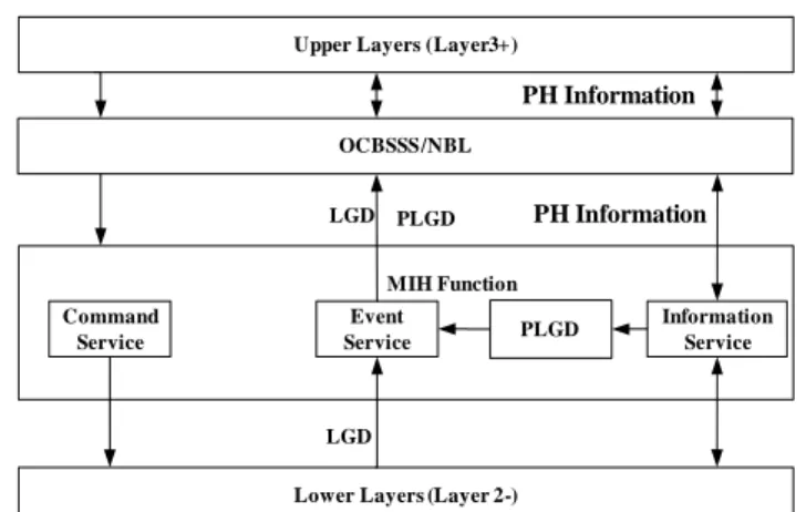
In this section, our proposed mechanism is outlined. The PLGD event which is designed in [12] is used in our mechanism. We define a PHIS Information structure in order to communicate the required information to the upper layer for the OCBSSS/NLB (Optimal Candidate Base Station Selection/Network Load Balancing) model. Using the PHIS the OCBSSS/NLB model selects the optimal candidate network and directs the handover based on the MN’s movement, BS geographical information and current network load. The information required to populate the PHIS will be received from the MIIS as shown in Figure 6. The event and information flow in the proposed model based on IEEE 802.11 MIH is shown in Figure 18.
A. Predicting_Handover Information
In our proposed mechanism, we use or PLGD event to inform the MN that a handover will be needed in a certain time based on the MN’s movement station, geographical information of the BS and the network load situation. The timing of such an event will provide sufficient time to enable the mobility protocol to select the optimal candidate BS and prepare for handover. The PLGD event is triggered by the following two conditions:
MN is going to move out of the current BS’s coverage;
The network load balancing is needed; this information can direct the MN to prepare handover. In these two situations the upper layer receives the PLGD event and PHIS which indicates when a handover is likely to occur. We use TPH to represent the estimated time at which
handover will be required.
When the MN is in motion, the PLGD and PHIS will be triggered based on the MN’s and AP’s geographical information, the MN’s moving situation, and the time needed for the predicated handover. When implementing network load balancing the PHIS will be sent to the upper layer based on the time needed for the predicted handover.
PLGD Configuration Neighbour Discovery IEEE 802.21 IS Required Handover Time Neighbour Discovery Scan Candidates Horizontal or Vertical HO Execution Link Down Candidates Decision Require HO Time PLGD Measurement Based on Geographical Information Prediction Time PLGD Trigger LD Trigger Predicting Link Going Down
Figure 7 Time Required for Preparing Handover
We use THO to represent the required preparing time for
the upcoming handover. THO is needed to adapt the current
session to the changed network conditions of the new path. In a multi-modal device these configurations occur on a redundant alternate path independent of the active communication on a primary path. Therefore the time required to prepare for handover is represented in Figure 7.
The expression of THO is presented in (2).
HO L HO L ate ScanCandid HO T T T T T NeighbourDiscovery 2 3
In (2), TNeighbourDiscovery is the time to indentify the
candidate networks, TScanCandidate is the time required to probe
those networks while TL2HO and TL3HO are the time required
to implement L3 and L2 handover.
B. CalculateTPH when MN is moving
The MIH standard addresses the support of handovers for both mobile and stationary users. For mobile users, handovers can occur when wireless link conditions change due to the users’ movement. For the stationary users, handovers become imminent when the neighborhood changes, making one network more attractive than the others. [1] The MIH standard supports cooperative use of information available at the MN and within the network infrastructure. The MN node is well-placed to detect available networks. The network infrastructure is well-suited to store overall network information, such as neighborhood cell lists, location of the MN, and higher layer service availability. Both the MN and the network make decisions about connectivity.
The handover process can be initiated by measurement reports and triggers supplied by the link layers on the MN.
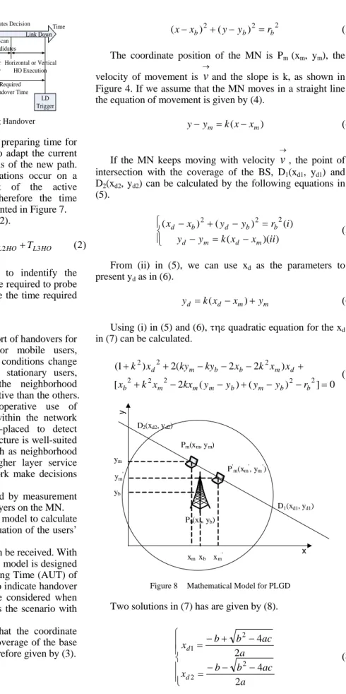
In this paper, we design a mathematic model to calculate the handover initial time based on the situation of the users’ movement.
With the MIIS, a lot of information can be received. With the information as the input, a mathematic model is designed for the MN to calculate the Available Using Time (AUT) of the BSs. The value of AUT can be used to indicate handover initiate time, and also can be used to be considered when select the optimal BS. Figure 4 illustrates the scenario with just one MN (Pm) and one BS (Pb).
From Figure 8, we can determine that the coordinate position of the BS is Pb(xb, yb) and the coverage of the base
station is rb. The coverage of the BS is therefore given by (3).
2 2 2
) ( )
(xxb yyb rb
The coordinate position of the MN is Pm (xm, ym), the
velocity of movement is
v
and the slope is k, as shown in Figure 4. If we assume that the MN moves in a straight line the equation of movement is given by (4). yymk(xxm)
If the MN keeps moving with velocity
v
, the point of intersection with the coverage of the BS, D1(xd1, yd1) andD2(xd2, yd2) can be calculated by the following equations in
(5). ) )( ( ) ( ) ( ) ( 2 2 2 ii x x k y y i r y y x x m d m d b b d b d
From (ii) in (5), we can use xd as the parameters to
present yd as in (6).
yd k(xdxm)ym
Using (i) in (5) and (6), quadratic equation for the xd
in (7) can be calculated. 0 ] ) ( ) ( 2 [ ) 2 2 ( 2 ) 1 ( 2 2 2 2 2 2 2 2 b b m b m m m b d m b b m d r y y y y kx x k x x x k x ky ky x k Pb(xb, yb) Pm(xm, ym) P’ m(xm’, ym’) xm ym xm’ ym’ x y D1(xd1, yd1) D2(xd2, yd2) yb xb
Figure 8 Mathematical Model for PLGD Two solutions in (7) has are given by (8).
a ac b b x a ac b b x d d 2 4 2 4 2 2 2 1
The coefficients for the equation in (7), a, b, c values are then calculated as in (9)
2 b 2 b m b m m 2 m 2 2 b m 2 b b m 2 r ) y (y ) y (y 2kx x k x c ) x 2k 2x ky 2(ky b k 1 a
We then calculate xd and yd as in (10) and (11).
)
(
),
,
min(
)
(
),
,
max(
' 2 1 ' 2 1 m m d d m m d d dx
x
when
x
x
x
x
when
x
x
x
yd k(xd xm)ym Suppose the MS’s current position is Pm (xm, ym), after
t
, the MN’s position will be Pm'(x'm,y'm), therefore k can be expressed in (12). m m m m y y x x k ''
The velocity can be calculated by: Pm (xm, ym),
) , ( ' ' ' m m m x y P and t in (13). t y y x x v m m m m 2 2 ' 2 ' ) ( ) ( We use 1 D Pm
d to present the distance from the MN’s location to the intersection, the value of
1 D Pm d can be calculated in (14). 2 ' 2 ' 2 ) ( ) ( 1 m d m d D P x x y y d m
We use TAUT to represent the time when the MN moves to the point of intersection. The value of TAUT can be calculated in (15). v D P d AUT T m 1
Finally, TAUT, the time when the MN moves out of the current BS’s coverage can be calculated in (16),
2 ' 2 ' 2 2 ' 2 ' 2 ) ( ) ( ) ( ) ( m m m m d m d m AUT T y y x x y y x x t
Using TAUT (calculated from the mathematic model), together with THO (the time needed to prepare for the handover) in (2), we can calculate TPL.
TPL TAUT THO
C. Optimal Candidate BS Selection
In this section, we introduce a method for selecting the optimal candidate network based on network load conditions. With this proposed method we can enhance the Resource Utilization and QoS.
The MIIS provides additional dynamic performance metrics which can be considered when selecting the optimal BSs for handover. In this paper, we focus on how to direct handover based on the MN’s movement, the neighborhood geographical information of candidate BSs, the network load of BSs and available bandwidth.
In our mechanism, we use Fuzzy MADM for handover selection which can improve the network QoS and satisfy the user. Suppose there are n BSs as the candidate BSs, when the optimal selection of candidate BS occurs, there are 4 attributes we take into consideration; the MN’s available time of use for BSs (X1), BSs’ resource utilization (X2),
bandwidth (X3) and MN moving direction relative to .BSs
(X4). Matrix X in (18) can be used to represent it. The
weights of each base station are W[w1 w2 w3 w4], the different weights are assigned to the parameters in order to diff the parameters’ importance levels.
4 3 2 1 24 23 22 21 14 13 12 11 4 3 2 1 2 1 n n n n n x x x x x x x x x x x x X X X X BS BS BS X
We use (16) to calculate the MN’s available use time of each BSs.
The algorithm then directs the handover to an underutilized area. The resource utilization of BSi is defined
in (19),
Ui max{Uiup,Uidown}
We use the one-zero association matrix A to describe the situation of each MN and BS. When aij=1 indicates that MNj
is associated to BSi, and when aij=0 indicates that MNj is not
associated to BSi.
The uplink resource utilization (Uiup) for BSi can be
i m j ij j up i uBandwidth a throughput U
1 ) ( where m is the total number of MNs in the system, thoughputj is the total throughput of flows in the downlink
for MNj, uBandwidthi is the uplink bandwidth. With the
similar manner, the downlink resource utilization is given in (21), i k j ij j down i dBandwidth a throughput U
1 ) ( The MN uses the MIIS to provide the network load conditions. We use (20) and (21) to calculate each BS’s resource utilization percent and select the optimal candidate BS based on the MN’s velocity and moving direction in the fuzzy rules. 1 Speed -3 -1 3 m/s Move Close to -2 0 1 2 Static Move Far Away
-4 4
μdirection(xspeed)
-5 5
Figure 9 Fuzzy Conversion Scale for MN’s Moving Direction Relative to BSs
We define the fuzzy set as follows, {Move Far Away, Static, Move Close to} to represent to represent the moving direction which is relative to the BSs. When the MN moves far away from the BSs, the speed is negative, and when the MN moves close to the BSs, the speed is positive. The membership functions of MN moving direction relative to BSs are shown in Figure 9. From Figure 9, when the MN’s moving velocity relative to BSs is 0. This indicates that the MN is static relative to BSs. The value of the moving direction relative to BSs is expressed in (22).
d direction(xspeed)i The factor i is a 0-1 factor which be calculated in (23). It is used to direct handover based on the MN’s moving direction relative to the BSs, when i is -1, which also means the MN is moving far away to the BSi, this will
reduce the chance of BSi being selected as the optimal
candidate. On the contrary when the value of i is 1, which also means the MN is moving close to the BSi, it will give a
positive influence to selecting BSi making it more likely to
be the optimal candidate BSs in the candidate BSs list.
) BS from away far oving is MN ( 1 ) BS to close moving MN static is MN ( 1 i i i i m
All of the values of matrix X are in different ranges which are needed to be normalized. We use matrix A to present the normalized values from matrix X. To normalize the attributes, firstly we use (24) to calculate the MN’s available use time of each BSs and bandwidth which are the benefit attributes, i i i ij ij x x x x a
We also use (25) to normalize the cost type of attribute of BSs’ resource utilization, i i ij i ij x x x x a
In (24) and (25), the value of xi and xi can be calculated in (26). ) ,..., , min( ) ,..., , max( 2 1 2 1 in i i i in i i i x x x x x x x x
The range of values in X4, the MN’s moving direction
relative to BSs, is not needed to normalized as it is already in the range [-1,1].
From (24) and (25), we can get the normalized matrix A as in (27). 4 3 2 1 24 23 22 21 14 13 12 11 n n n n a a a a a a a a a a a a A
The goal of the decision logic is to determine the most satisfactory candidate BS among the set n. We can use (28) to implement this selection.
4 3 2 1 4 3 2 1 4 3 2 1 24 23 22 21 14 13 12 11 s s s s w w w w a a a a a a a a a a a a W A S n n n n
In (28), matrix S[s1 s2 s3 s4]T is the score for the all candidate BSs, the optimal candidate BSopt can be got
in (29).
Sopt max(s1,s2,...,sn)
D. NLB Model
In terms of implementing network load balancing, the most important considerations are:
Network Load Metric
Network Load Measurement
Network Load Balancing Operation
In this paper we design our model to use directed handover as the method of realizing network load balancing. In this section we initially discussed mechanisms to measure network load status and define load balancing metrics. Methods to operate network balancing are then introduced.
(1) Network Load Balancing Metric
The load metric should describe the load situation in relations to the network resources utilization.
Commonly the number of calls and blocking probability are used as load metrics in traditional cellular networks. In wireless networks such as WLAN, packet loss, throughput and delay are used to describe the networks load status.
In this paper, we mainly focus on the throughput of the each BS compared to the BS’s bandwidth. Using the throughput and bandwidth of the BS we can get the each BS’s network resource utilization.
(2) Network Load Measurement
To evaluate the balancing situation of the system, we use the average load of the whole system as in (30),
n L n i Ui
1 ~ where n is the number of the BSs, and Ui is the resource
utilization situation of BSi.
The factor l in (31) is then used to describe the load state of the whole system,
,( [0,1]) ) ( ) ( 1 2 2 1
l n i U n i U l i i n the value of l[0,1], where 1 indicates that the network load of the whole system is balanced. The higher value of
l
shows the more unbalanced of the network load in the whole system.
(3) Network Load Balancing Operation
In this section we introduce the method of selecting the optimal candidate BSs when the handover is necessary due
to MN mobility. Using this method the number of handovers can be reduced. However as the number of MNs increases, the network will be unbalanced during certain periods.
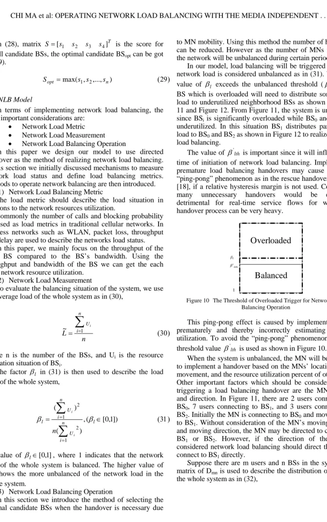
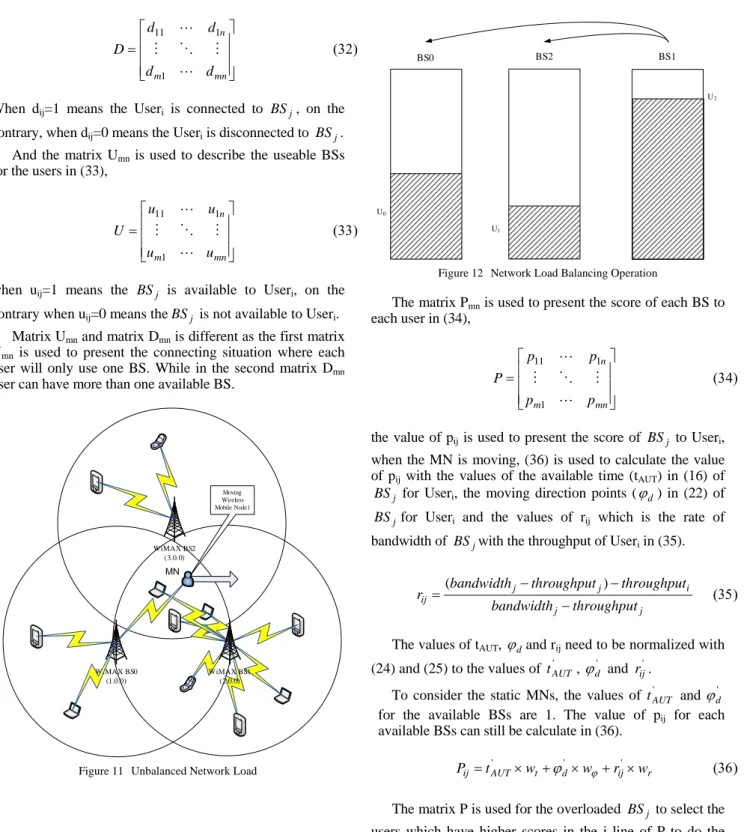
In our model, load balancing will be triggered when the network load is considered unbalanced as in (31). When the value of l exceeds the unbalanced threshold ('lth), the BS which is overloaded will need to distribute some of the load to underutilized neighborhood BSs as shown in Figure 11 and Figure 12. From Figure 11, the system is unbalanced since BSi is significantly overloaded while BS0 and BS2 are
underutilized. In this situation BS1 distributes parts of the
load to BS0 and BS2 as shown in Figure 12 to realize network
load balancing.
The value of 'lth is important since it will influence the time of initiation of network load balancing. Implementing premature load balancing handovers may cause a similar “ping-pong” phenomenon as in the rescue handover decision [18], if a relative hysteresis margin is not used. Conducting many unnecessary handovers would be especially detrimental for real-time service flows for which the handover process can be very heavy.
Balanced
Overloaded
1
Figure 10 The Threshold of Overloaded Trigger for Network Load Balancing Operation
This ping-pong effect is caused by implementing NLB prematurely and thereby incorrectly estimating resource utilization. To avoid the “ping-pong” phenomenon, a lower threshold value 'lth is used as shown in Figure 10.
When the system is unbalanced, the MN will be required to implement a handover based on the MNs’ location, MNs’ movement, and the resource utilization percent of other BS’s. Other important factors which should be considered when triggering a load balancing handover are the MN velocity and direction. In Figure 11, there are 2 users connecting to BS0, 7 users connecting to BS1, and 3 users connecting to
BS2. Initially the MN is connecting to BS0 and moving close
to BS1. Without consideration of the MN’s moving velocity
and moving direction, the MN may be directed to connect to BS1 or BS2. However, if the direction of the MN is
considered network load balancing should direct the MN to connect to BS1 directly.
Suppose there are m users and n BSs in the system, the matrix of Dmn is used to describe the distribution of users in
mn m n d d d d D 1 1 11
When dij=1 means the Useri is connected to BSj, on the contrary, when dij=0 means the Useri is disconnected to BSj.
And the matrix Umn is used to describe the useable BSs
for the users in (33),
mn m n u u u u U 1 1 11
when uij=1 means the BSj is available to Useri, on the
contrary when uij=0 means theBSj is not available to Useri.
Matrix Umn and matrix Dmn is different as the first matrix
Umn is used to present the connecting situation where each
user will only use one BS. While in the second matrix Dmn
user can have more than one available BS.
WiMAX BS2 (3.0.0) WiMAX BS0 (1.0.0) Moving Wireless Mobile Node1 WiMAX BS1 (2.0.0) MN
Figure 11 Unbalanced Network Load
BS0 BS2 BS1
U0
U1
U2
Figure 12 Network Load Balancing Operation
The matrix Pmn is used to present the score of each BS to
each user in (34), mn m n p p p p P 1 1 11
the value of pij is used to present the score of BSj to Useri,
when the MN is moving, (36) is used to calculate the value of pij with the values of the available time (tAUT) in (16) of
j
BS for Useri, the moving direction points (d) in (22) of j
BS for Useri and the values of rij which is the rate of
bandwidth of BSjwith the throughput of Useri in (35).
j j i j j ij throughput bandwidth throughput throughput bandwidth r ( )
The values of tAUT, dand rij need to be normalized with
(24) and (25) to the values of t'AUT, d' and rij'. To consider the static MNs, the values of tAUT' and
'
d
for the available BSs are 1. The value of pij for each
available BSs can still be calculate in (36).
PijtAUTwt dw rijwr ' ' '
The matrix P is used for the overloaded BSj to select the users which have higher scores in the j line of P to do the directing load to the other underloaded BSs list when doing the network load balancing. In this way, only users who have more than one available BS can be selected to do handover. The resulting handover should also provide users with better QoS as a result of the score calculated in (36).
V. SIMULATION AND EVALUATION
In this section, we evaluate our approach using NS2 [2] together with the WiMAX MIH mobility package from NIST [3].
In our mechanism, the network performance is improved by two methods; utilizing a PLGD event to estimate handover initiate time and operating network load balancing by directing handover from overloaded or underutilized BSs area. We therefore evaluate network performance in two aspects, handover performance and the network QoS.
Handover cost can be used to evaluate the handover performance. The handover initiation and handover duration time can be used to evaluate the handover costs. In this paper, we compare the handover costs for three handover mechanisms: i) the PLGD handover; ii) the LGD handover with a pre-defined LGD threshold ( 1.1); iii) the LD handover (handover without any predictive method).
To evaluate the effect of NLB operation, we can compare the QoS of the networks (eg., Jitter and Delay) after the operation of NLB to the situation of unbalanced load system.
A. Scenario Description
Figure 13 illustrates the topological structure of the simulated networks. Figure 14 illustrates the geographical information of the networks. 3 BSs are defined, BS0, BS1 and BS2, their locations are (1000,1000), (2000,1000) and (1500,2000). 12 users are defined, the MN0, MN1, MN2, MN3, MN4, MN5, MN6, MN7, MN8, MN9, MN10, and a wireless node WlNode11, their locations are MN0(500, 1250), MN1(750,500), MN2(1000,2250), MN3(1400,1200), MN4(1500,2550), MN5(1600,1400), MN6(1600,1200), MN7(1700,800), MN8(1600,1200), MN9(2500,500), MN10(2500,1250), and WlNode(1600,1400). While all the MNs are distributed amongst the three BSs, BS1 is configured to be significantly more congested than BS0 and BS2. Router0 UMTS BS2 WiMAX BS0 WiMAX BS1 Router1 sinkNode0 sinkNode2 sinkNode1 Router0 MN4 MN2 MN6 MN3 MN0 MN1 MN7 MN8 MN10 MN9 wlNode MN5
Figure 13 Topologic Diagram of the Network
In the proposed network simulation environment, MN0 and MN1 are the receivers which are connected to the BS0. sinkNoder0 is the sender and starts sending Constant Bit Rate (CBR) video traffic streams with packet size of 4960 bytes at 0.02 second intervals. MN3, MN5, MN6, MN7, MN8, MN9 and MN10 are the receivers which are connected to BS1.
sinkNode1 is another sender and starts sending CBR video traffic streams with packet size of 4960 bytes at 0.02 second intervals. MN2 and MN4 are the receivers which are connected to BS2. sinkNode2 is the third sender and starts sending CBR video traffic streams with packet size of 4960 bytes at 0.02 second intervals.
BS2 (1500,2000) BS0 (1000,1000) BS1 (2000,1000) MN2 (1000,2250) MN6 (1600,1200) MN3 (1400,1200) MN0 (500,1250) MN1 (750,500) MN7 (1700,800) MN10 (2500,1250) MN9 (2250,500) y x MN4 (1500,2550) wlNode (1600,1600) MN5 (1600,1400) MN8 (1600,1200)
Figure 14 Geographical Map of the Scenario
wlNode is the only mobile node in the system. Initially wlNode uses BS0. After 10s wlNode moves from (1600,1600) in a easterly direction to (1600,3000) at different velocities. wlNode is the receivers while sinkNode0 is the sender which starts sending CBR video traffic streams with packet size of 4960 bytes at 0.02 second intervals. Different of speeds, 1m/s, 2m/s, 3m/s, 5m/s, 10m/s and 20m/s are used to evaluate the influence of velocity for the vehicular based system when do the simulation experiments. Figure 14 illustrates that wlNode will require a handover as it moves out of the coverage of BS0. As the simulation is configured, network load balancing will also be required as BS1 is much congested compared to the neighboring BS0 and BS2.
B. Test Results and Evaluation
In our model, the handover initiation time is dependent on the MN’s velocity. The estimated time of current path failure is sent to the upper layer by the PLGD event to provide the upper layer mobility protocol with sufficient time to prepare handover process prior to actual current path failure.
To analyze handover performance, the handover start time (tstart) which is the time that the last packet is received
from the previous network, the handover end time (tend)
which is the time that the first packet is received from the later network is used to evaluate handover duration time (thandover) in (37).
thandover tstarttend
The handover start time in TABLE I describes the time when the handover is initiated for each of the approaches; LD event, LGD event (1.1 )and PLGD event. To evaluate the influence of velocity in the vehicular based system, different speed is used as in TABLE I. From TABLE I, the results illustrate that handover initiate time of the LGD event is earlier than PLGD event when the speed is less than 5m/s. In the situation where the user’s speed is faster however, the LGD event’s handover initiate time is later than PLGD event. In this scenario as a result of the high velocity of the user’s movement, the LGD event would provide insufficient notice to the upper layer to prepare for handover prior to underlying path failure.
TABLE IHANDOVER START TIME
Speed LD LGD PLGD 1m/s 109.9590783 106.7023121 109.7590783 2m/s 59.9590783 58.654353 49.7590783 3m/s 43.3030783 42.6545345 33.1030783 5m/s 29.9590783 29.85435342 29.7590783 6m/s 26.6550783 26.65523443 26.4550783 10m/s 19.959078299 19.959435435 19.759078299 20m/s 14.959078297 14.80732434 14.759078297
Figure 15 Handover Duration Time
The handover duration time when using the LD, LGD and PLGD events are shown in Figure 15. The results illustrate that the LD event is unacceptable as the handover duration time is over 700ms. This is because with the LD events didn’t prepare the handover before the current link goes down, in this way, a lot of time is spent on neighbor discovery mechanism, switching of channel and network entry.
When utilizing the PLGD event, the handover duration time is significantly improved over the LGD event approach when the user’s speeds are faster than 5m/s.
Figure 19 shows the distribution of the users in the system after NLB implementation when the MN moves in an eastward direction. Following NLB the MN3 and MN6 receive a directed handover to BS2 while MN7 receives a directed handover to BS0.
Figure 20 shows the distribution of the users in the system after NLB implementation when the MN moves in an northward direction. In such a scenario wlNode receives a directed handover to BS2, MN3 and MN7 receive directed handover to BS0 from BS1, and MN5 receives a directed handover to BS2 from BS1.
Figure 21 shows the distribution of the users in the system after NLB implementation when the MN moves in an westward direction. In such a scenario MN3 receives a directed handover to BS0 from BS1, while MN5 and MN6 receive directed handover to BS2 from BS1.
Figure 22 shows the distribution of the users in the system after NLB implementation when the MN moves in an southward direction. In such a scenario MN3 receives a directed handover to BS0 from BS1, while MN5 and MN6 receive directed handover BS2 from BS1.
The results of delay and jitter before and after operated network load balancing are shown in Figure 23, Figure 24 and Figure 31. Compare Figure 23 and Figure 24, the results shows that after the implementation of NLB jitter is reduced significantly. Figure 31 also illustrates the delay is reduced after the implementation of NLB.
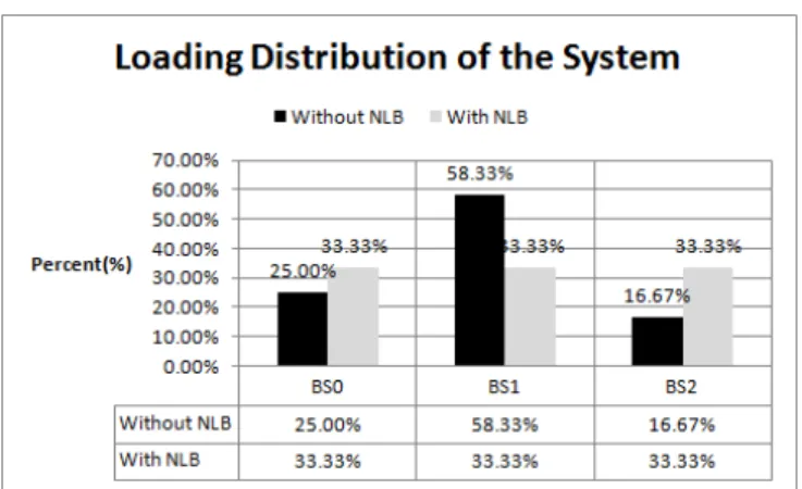
Figure 17 shows the results of comparing the loading distribution in the whole system with and without implementing NLB. From Figure 17, we can see that the implementation of NLB has directed the load from the overloaded BS1 towards the underutilized BS0 and BS2. Figure 16 indicates that average delay is reduced significantly with the implementation of NLB when the wlNode moves in various directions.
Figure 16 Average Delay Comparison Utilizing NLB and without Utilizing NLB
All of the results presented illustrate that when the proposed model is utilized, the time estimated for handover
initiation is close to optimal as the algorithm for selecting optimal candidate BS takes the user’s mobility into consideration. Also the operation of NLB improves network utilization and QoS significantly.
Figure 17 Network Loading Distributation of the Whole System VI. CONCLUSION AND FUTURE WORK
In this paper, a novel model for vehicular based system is proposed which utilizes predictive seamless handover across heterogeneous wireless network and realization of network load balancing based on neighborhood geographical and network load real time information. In particular we use a PLGD event which utilized the estimated time of network link down time by a mathematical model based on the MN’s and BSs’ geographical information and MN’s movement information. With the PLGD event, the upper layer mobility protocol can prepare sufficient time to initiate the handover before actual network path failure. Secondly, a novel PHIS Information structure is designed in MIIS to collect the network load information and neighborhood geographical information. This PHIS can be utilized when selecting the optimal candidate network during handover and operating network load balancing. A Fuzzy MADM algorithm is implemented to select the optimal candidate network based on the MN’s available usage time of a BS, BSs’ resource utilization, bandwidth and MN moving direction relative to BSs. Furthermore, we design and realized the method of implementing network load balancing by directing handover from overloaded to underutilized BS.
We present results for vehicular oriented simulation in NS2 which illustrate that our model reduced handover duration time significantly when MN’s velocity exceeds 5ms. The results also illustrate that with the implementation of network load balancing in our mechanism, delay is reduced by 1ms and jitter is nearly closed to 0, illustrating a significant improvement in QoS.
In the future, the proposed mechanism could be improved by researching on setting the weighting matrix W, when selecting the optimal candidate network and when the overload BSs making the decision of selecting nodes to handover to the underutilized networks. And more complex and random scenarios will be considered to test the performance of the mechanism in the future research.
REFERENCES
[1] Institute of Electrical and Electronics Engineers, “IEEE Standard for Local and metropolitan area networks – Part 21: Media Independent Handover Services”, LAN/MAN Standards Committee of the IEEE Computer Society, 21 Jan. 2009.
[2] UC Berkeley, LBL, UCS/ISI, Xerox Parc (2005). NS-2 Documentation and Software, Version 2.29. http://www.isi.edu/nsnam/ns
[3] NIST. National Institute of Standards and Technology. http://www.antd.nist.gov/
[4] S.J. Yoo, D. Cypher, N. Golmie, “Predictive Handover Mechanism based on Required Time Estimation in Heterogeneous Wireless Networks”. Military Communications Conference. San Diego, CA.pp. 7-7 IEEE 16-19 Nov. 2008
[5] P. Neves, F. Fontes, S. Sargento, M. Melo, and K. Pentikousis, “Enhanced Media Independent Handover Framework” Vehicular Technology Conference, VTC Spring 2009. IEEE 69th, pp. 1-5, April
2009
[6] E. Fallon, Y. Qiao, L. Murphy, G. Muntean, “SOLTA: a service oriented link triggering algorithm for MIH implementations”, Proceedings of the 6th International Wireless Communications and Mobile Computing Conference, Caen, France, pp. 1146-1150, 2010 [7] S. Yoo, D. Cypher, and N. Golmie, “Predictive Link Trigger
Mechanism for Seamless Handovers in Heterogeneous Wireless Networks”, published online at www3.interscience.wiley.com, Wireless Communications and Mobile Computing.
[8] S. Yoo, D. Cypher, N. Golmie “Timely Effective Handover Mechanism in Heterogeneous Wireless Networks”, Journal, Wireless Personal Communications, vol. 55, pp. 449-475, 2008
[9] K.R Kumar, P. Angolkar, D. Das, “SWiFT: A Novel Architecture for Seamless Wireless Internet for Fast Trains”, Ramalingam, R.Vehicular Technology Conference, Sinfapore, 2008. VTC Spring 2008. IEEE, pp. 3011-3015, May 2008
[10] S.F. Yang, J.S. Wu, H.H. Huang, “A vertical Media-Independent Handover decision algorithm across Wi-Fi™ and WiMAX™ networks”, WOCN '08. 5th IFIP International Conference on Wireless and Optical Communications Networks, Surabaya, pp. 1-5, May 2008 [11] I. Joe, M.C. Shin ,“A Mobility-Based Prediction Algorithm with
Dynamic LGD Triggering for Vertical Handover”, Consumer Communications and Networking Conference (CCNC), 2010 7th IEEE, pp. 1-2
[12] C. Ma, E. Fallon, Y. Qiao, B. Lee, “Optimizing Media Independent Handover Using Predective Geographical Information for Vehicular Based Systems”, UKSim 4th European Modelling Symposium on Mathematical Modelling and Computer Simulation (EMS 2010), Pisa, Italy, 17-19 November 2010.
[13] Bejerano, Y., Seung-Jae Han, “Cell Breathing Techniques for Load Balancing in Wireless LANs”, IEEE Transactions on Mobile Computing, June 2009, vol. 8, pp. 735 – 749
[14] Garcia, E., Vidal, R., Paradells, J., “Cooperative load balancing in IEEE 802.11 networks with cell breathing”, Computers and Communications, 2008. ISCC 2008. IEEE Symposium on, Marrakech, July 2008, pp. 1133 – 1140.
[15] S. H. Lee and Y. Han, ”A Novel Inter-FA Handover Scheme for Load Balancing in IEEE 802.16e System,” IEEE 65th Vehicular Technology Conference, 2007, pp. 763 - 767, April 2007.
[16] E. Yanmaz and O.K. Tonguz, ”Handover performance of dynamic load balancing schemes in cellular networks,” 10th IEEE Symposium on Computers and Communications, 2005, pp. 295 - 300, June 2005. [17] D. Kim, M. Sawhney, and H. Yoon, ”An effective traffic
management scheme using adaptive handover time in next-generation cellular networks,” International Journal of Network Management, Volume 17, Issue 2, pp. 139 - 154, March 2007.
[18] T. Casey, N. Veselinovic, and R. Jantti, ”Base Station Controlled Load Balancing with Handovers in Mobile WiMAX”, PIMRC 2008.
IEEE 19th International Symposium on Personal, Indoor and Mobile Radio Communications, pp.1-5, December 2008.
MIHF Event Service Other Triggers Link Layer Link Indications Network Node Other Sources MIHF Event Service Other Triggers Link Layer Link Indications Network Node Remote Event Service MIHF Information Service (Client)
User Equipment Network Information Service Provider(NISP) MIHF Information Service (Server) Information Database
Interface between UE and Network Information Service
Provider
Interface between Information Service Function and Information
Database
MIHF Information
Service (Client)
User Equipment Network Information Service Provider(NISP) MIHF Information Service (Server) Information Database
Interface between UE and Network Information Service
Provider
Interface between Information Service Function and Information
Database MIHF Information Service (Proxy) Proxy NISP
Interface between two Network Information Service providers
Other Sources
Router0 ID 1 (0.0.1) UMTS BS2 (5.0.0) WiMAX BS0 ID6 (3.0.0) WiMAX BS1 ID7 (4.0.0) Router1 ID3 (1.0.1) sinkNode0 ID0 (0.0.0) sinkNode2 ID4 (2.0.0) sinkNode1 ID2 (1.0.0) Router0 ID5 (2.0.1) MN2(2) ID17 (5.0.3) MN2(1) ID16 (5.0.2) MN2(8) ID23 (4.0.9) MN2(7) ID22 (4.0.8) MN0(0) ID9 (3.0.1) MN0(1) ID10 (3.0.2) MN0(3) ID12 (3.0.4) MN0(2) ID11 (4.0.3) MN1(0) ID13 (4.0.1) MN1(1) ID14 (4.0.2) wlNode0 ID24 (3.0.5) MN2(7) ID22 (4.0.8) Router0 ID 1 (0.0.1) UMTS BS2 (5.0.0) WiMAX BS0 ID6 (3.0.0) WiMAX BS1 ID7 (4.0.0) Router1 ID3 (1.0.1) sinkNode0 ID0 (0.0.0) sinkNode2 ID4 (2.0.0) sinkNode1 ID2 (1.0.0) Router0 ID5 (2.0.1) MN2(2) ID17 (5.0.3) MN2(1) ID16 (5.0.2) MN2(8) ID23 (4.0.9) MN2(7) ID22 (4.0.8) MN0(0) ID9 (3.0.1) MN0(1) ID10 (3.0.2) MN0(3) ID12 (3.0.4) MN0(2) ID11 (4.0.3) MN1(0) ID13 (4.0.1) MN1(1) ID14 (4.0.2) wlNode0 ID24 (3.0.5) MN2(7) ID22 (4.0.8)
Figure 19 The Distribution of Users after Operate NLB (East) Figure 20 The Distribution of Users after Opreate NLB (North)
Router0 ID 1 (0.0.1) UMTS BS2 (5.0.0) WiMAX BS0 ID6 (3.0.0) WiMAX BS1 ID7 (4.0.0) Router1 ID3 (1.0.1) sinkNode0 ID0 (0.0.0) sinkNode2 ID4 (2.0.0) sinkNode1 ID2 (1.0.0) Router0 ID5 (2.0.1) MN2(2) ID17 (5.0.3) MN2(1) ID16 (5.0.2) MN2(8) ID23 (4.0.9) MN2(7) ID22 (4.0.8) MN0(0) ID9 (3.0.1) MN0(1) ID10 (3.0.2) MN0(3) ID12 (3.0.4) MN0(2) ID11 (4.0.3) MN1(0) ID13 (4.0.1) MN1(1) ID14 (4.0.2) wlNode0 ID24 (3.0.5) MN2(7) ID22 (4.0.8) Router0 ID 1 (0.0.1) UMTS BS2 (5.0.0) WiMAX BS0 ID6 (3.0.0) WiMAX BS1 ID7 (4.0.0) Router1 ID3 (1.0.1) sinkNode0 ID0 (0.0.0) sinkNode2 ID4 (2.0.0) sinkNode1 ID2 (1.0.0) Router0 ID5 (2.0.1) MN2(2) ID17 (5.0.3) MN2(1) ID16 (5.0.2) MN2(8) ID23 (4.0.9) MN2(7) ID22 (4.0.8) MN0(0) ID9 (3.0.1) MN0(1) ID10 (3.0.2) MN0(3) ID12 (3.0.4) MN0(2) ID11 (4.0.3) MN1(0) ID13 (4.0.1) MN1(1) ID14 (4.0.2) wlNode0 ID24 (3.0.5) MN2(7) ID22 (4.0.8)
Figure 23 WlNode Jitter before Opreate NLB (East) Figure 24 WlNode Jitter after Operate NLB (East)
Figure 25 WlNode Jitter before Opreate NLB (North) Figure 26 WlNode Jitter after Operate NLB (North)
Figure 29 WlNode Jitter before Opreate NLB (South) Figure 30 WlNode Jitter after Operate NLB (South)
Figure 31 WlNode Average Delay Comparison (East) Figure 32 WlNode Average Delay Comparison (North)