DRO
Deakin Research Online,
Deakin University’s Research Repository Deakin University CRICOS Provider Code: 00113B
Feedback linearizing model predictive excitation controller design for
multimachine power systems
Citation:
Orchi, T. F., Roy, T. K., Mahmud, M. A. and Amanullah M. T. Oo 2017, Feedback linearizing
model predictive excitation controller design for multimachine power systems
, IEEE Access
,
vol. 6, pp. 2310-2319.
DOI:
http://www.dx.doi.org/10.1109/ACCESS.2017.2782782
© 2017, IEEE
Reproduced within the terms of the IEEE OAPA (Open Access Publishing Agreement).
Downloaded from DRO:
Received October 6, 2017, accepted November 27, 2017, date of publication December 13, 2017, date of current version February 14, 2018.
Digital Object Identifier 10.1109/ACCESS.2017.2782782
Feedback Linearizing Model Predictive
Excitation Controller Design for
Multimachine Power Systems
T. F. ORCHI, (Student Member, IEEE), T. K. ROY , (Student Member, IEEE), M. A. MAHMUD , (Member, IEEE), AND AMANULLAH M. T. OO, (Member, IEEE)
Electrical Power and Energy Systems Research Lab, School of Engineering, Deakin University, Geelong, VIC 3216, Australia Corresponding author: M. A. Mahmud ([email protected])
ABSTRACT In this paper, a nonlinear excitation controller is designed for multimachine power systems in order to enhance the transient stability under different operating conditions. The two-axis models of synchronous generators in multimachine power systems along with the dynamics of the IEEE Type-II exci-tation systems are considered to design the proposed controller. The partial feedback linearization scheme is used to simplify the multimachine power system as it allows decoupling a multimachine power system based on the excitation control inputs of synchronous generators. A receding horizon-based continuous-time model predictive control scheme is used for partially linearized power systems to obtain linear control inputs. Finally, the nonlinear control laws, which also include receding horizon-based control inputs, are implemented on the IEEE 10-machine, 39-bus New England power system. The superiority of the proposed scheme is evaluated by providing comparisons with a similar existing nonlinear excitation controller, where the control input for the feedback linearized model is obtained using the linear quadratic regulator (LQR) approach. The simulation results demonstrate that the proposed scheme performs better as compared to the LQR-based partial feedback linearizing excitation controller in terms of enhancing the stability margin.
INDEX TERMS Receding horizon, model predictive controller, excitation controller, feedback linearization, power systems stability, synchronous generators.
I. INTRODUCTION
Power systems are nonlinear and complex interconnected systems which operate close to their stability margin, i.e., heavily stressed to meet the continuously varying load demand. When the small or large disturbances occur on stressed power systems, there exist low-frequency local area as well as inter-area oscillations which degrade the overall stability margin [1]. The excitation controller of synchronous generators is used to damp these low-frequency oscillations in power systems by providing the additional damping into the system.
The power system stabilizer (PSS) is extensively used as the supplementary excitation controller over last few decades [2]–[4]. Though the PSSs are very effective to damp low-frequency oscillations, these require the fine tuning of parameters in order to achieve the desired control objectives. Some advanced linear excitation controllers are proposed in [5]–[7] to efficiently damp low-frequency oscillations in power systems as compared to the PSS. However, both PSSs
and linear excitation controllers as reported in [2]–[7] are designed by considering the linearized model of power sys-tems. Therefore, these excitation controllers ensure the oper-ation of power systems over a limited operating region.
Nonlinear excitation controllers overcome the limitations of operating points as nonlinear models are used to design these excitation controllers [8]. A passivity-based nonlinear excitation controller is proposed in [9] for a single machine infinite bus (SMIB) system by choosing interconnection and damping matrices. However, the selection of these matrices are difficult for the large-scale power system with multiple generators. The sliding mode excitation controllers (SMECs) are used in [10] and [11] to improve the transient stabil-ity of power systems. The main problem of the SMECs is the well-known chattering effects which may excite the unmodeled electrical dynamics of synchronous generators and usually appear as vibrations in the mechanical parts [12]. These vibrations cause undesirable operations which in turn lead to a low control performance.
2310
2169-35362017 IEEE. Translations and content mining are permitted for academic research only. Personal use is also permitted, but republication/redistribution requires IEEE permission. See http://www.ieee.org/publications_standards/publications/rights/index.html for more information.
Recently, adaptive backstepping excitation controllers are proposed in [13]–[15] to provide robust performance against the parametric uncertainties if the adaptation gains are prop-erly selected. Therefore, the precise knowledge and operating characteristics of the system are pre-requisites in order to obtain the proper values of adaptation gains. A nonlinear model predictive excitation controller (NMPEC) is proposed in [16] and [17] without optimizing the cost function. The main feature of the NMPEC is that it can provide robustness against the unmodeled dynamics of power systems. How-ever, the accuracy of the NMPEC in [16] and [17] relies on the prediction horizon and control order which makes the NMPEC bit complicated. Moreover, the NMPEC in [16] and [17] uses rotor angle of synchronous generators as a feedback which is not directly measurable.
Feedback linearizing excitation controllers are used to enhance the transient stability of power systems in a much better way while comparing with other nonlinear tech-niques [18]. An exact feedback linearizing excitation con-troller is used in [19] for improving the stability margin of power systems under different operating scenarios. How-ever, the implementation of exact feedback linearizing exci-tation controllers requires the rotor angle estimation using an observer [20]. Similarly, the direct feedback linearization scheme is widely used to design excitation controllers which also uses rotor angle as the state feedback [21], [22]. Though the problem of rotor angle measurement can easily be solved by using state observers, the control structure becomes more complicated. A partial feedback linearizing excitation con-troller (PFBLEC), which does not use the rotor angle as the state feedback rather than the speed deviation, is used in [23]. As the speed deviation is the derivative of the rotor rotor angle, the PFBLEC provides more damping into the system as compared to other feedback linearizing excitation controllers. Most of these existing feedback linearization approaches use the linear quadratic regulator (LQR)-based controllers for the feedback linearized system which suffer from robustness in presence of large external disturbances or uncertainties.
The literature on the excitation controller design so far discussed in this paper mainly considers the synchronous generator in power systems as one-axis though some of these literature include the dynamics of excitation systems. These one-axis models represent synchronous generators as simple voltage sources behind the transient reactance which cannot capture the full dynamic characteristics of power systems. Moreover, the characteristics of synchronous generators are quite complicated while considering the practical applica-tions. The two-axis model of synchronous generator is used in [24] to design adaptive backstepping excitation controller without considering the dynamics of the excitation system. Recently, the partial feedback linearization scheme along with an LQR approach is used in [25] to design excita-tion controller for the higher models (considering two-axis models) of synchronous generators. The excitation controller in [25] provides robustness against both parametric and state dependent uncertainties within a certain boundary
which is a key limitation. Moreover, the performance of LQR-based PFBLEC heavily relies on the selection of weighting matrices.
This paper focuses to design a nonlinear excitation con-troller by considering the two-axis model of synchronous generators in a multimachine power system where the existing partial feedback linearization scheme as presented in [23] and [25] is used to linearize multimachine power sys-tems. The linear controller for the feedback linearized power system model is designed based on the receding horizon-based model predictive control (RH-MPC) scheme. The main feature of the proposed scheme is that the power system model is a partially linearized one which simplifies the linear controller design procedure by reducing the order of the feedback linearized system. At the same time, the proposed continuous-time RH-MPC ensures that the desired control objectives are achieved with minimal control efforts. Another important feature of the MPC is that it allows to predict the future characteristics of power systems based on the input-output relationships which exactly fits with the features of the feedback linearization as it linearizes nonlinear multi-machine power systems based on the input-output relation-ships. An IEEE 10-machine 39-bus test power system is used to evaluate the performance of the proposed scheme as it exhibits the characteristics of a large-scale system.
II. POWER SYSTEM MODEL
The complexities in modeling power systems depend on several factors such as the required degrees of accura-cies, intended applications, etc. Despite these factors, some assumptions are always made during the power system mod-eling as the actual behaviors of different components are complicated [26]. The dynamical models of synchronous generators and IEEE Type–II excitation systems are consid-ered in order to design the excitation controller. Therefore, the dynamics of both synchronous generators and excitation sys-tems are considered to model power syssys-tems [3], [27], [28]. The synchronous generators have both mechanical and elec-trical dynamics. By consideringN numbers of synchronous generators in a multimachine power system, the mechanical and electrical dynamics (based on the two-axis model) of
ith machine can be represented in terms of the following equations [3]: ˙ δi =ωi−ω0i ˙ ωi = − Di 2Hi (ωi−ω0i)+ ω0i 2Hi (Pmi−Pei) ˙ Eqi0 = 1 Tdoi0 h −Eqi0 −(xdi−xdi0 )Idi+Efdi i ˙ Edi0 = 1 Tqoi0 h −Edi0 +(xqi−xqi0 )Iqi i (1)
where the symbols are defined in a usual manner which can be found in [25]. The relevant network equations in terms of different physical properties of power systems, e.g., voltage,
T. F. Orchiet al.: FBL Model Predictive Excitation Controller Design
current, power, etc. and loads can be written as follows:
Vdi =Edi0 −RsiIdi+xqi0 Iqi Vqi =Eqi0 −RsIqi−xdi0 Idi Vti = q Vdi2+Vqi2 IdiVisin(δi−θi)+IqiVicos(δi−θi)+PLi(Vi) − n X j=1 ViVjYijcos(θi−θj−αij)=0 IdiVicos(δi−θi)−IqiVisin(δi−θi)+QLi(Vi) − n X j=1 ViVjYijsin(θi−θj−αij)=0 PLi(Vi)− n X j=1 ViVjYijcos(θi−θj−αij)=0 QLi(Vi)− n X j=1 ViVjYijsin(θi−θj−αij)=0 PLi(Vi)=P0LiV kpi i QLi(Vi)=Q0LiV kqi i (2)
where the symbols have their usual meanings as presented in [25]. The load is constant power load whenkpi=kqi=0
whilekpi =kqi =1 indicates the load as a constant current
load andkpi=kqi=2 as the constant impedance load.
By neglecting the saliency of synchronous generators, i.e., by consideringxdi0 = xqi0 , the equations for currents can be simplified as follows [29], [30]: Idi= n X j=1 Yij h Edj0 cos(δji+θij)−Eqj0 sin(δji+θij) i Iqi= n X j=1 Yij h Eqj0 cos(δji+θij)+Edj0 sin(δji+θij) i (3) Similarly, the output active and reactive power of the genera-tor will be modified as follows:
Pei =Eqi0Iqi+Edi0Idi
Qei =Eqi0Idi−Edi0Iqi (4)
The dynamics of an IEEE Type–II exciter can be repre-sented by the following equation [31], [32]:
˙ Efdi= 1 TAi −Efdi+KAi(Vrefi+Vci−Vti) (5) where the symbols have their usual meanings as presented in [25].
Finally, the dynamical model ofithsynchronous generator along an IEEE Type II exciter can be written as follows:
˙ δi =ωi−ω0i ˙ ωi = − Di 2Hi (ωi−ω0i)+ ω 0i 2Hi (Pmi−Pei) ˙ Eqi0 = 1 Tdoi0 −Eqi0 −(xdi−xdi0)Idi+Efdi ˙ Edi0 = 1 Tqoi0 −Edi0 +(xqi−xqi0 )Iqi ˙ Efdi = 1 TAi −Efdi+KAi(Vrefi+Vci−Vti) (6) The mathematical model of a power system with mul-tiple synchronous generators can be written in the fol-lowing generalized nonlinear systems with multi-input multi-output (MIMO): ˙ x=f(x)+ N X i=1 gi(xi)ui y=h(x) (7)
wherei=1, 2, · · ·,N. Equation (7) is composed of several subsystems as the power system is affine nonlinear system and hence, the nonlinear form ofithsubsystem can be written as: ˙ xi =fi(xi)+gi(xi)ui yi =hi(xi) (8) where ˙ xi = h ˙ δi ω˙i E˙qi0 E˙di0 E˙fdi iT fi(xi)= ωi−ω0i −Di 2Hi (ωi−ω0i)+ ω0i 2Hi (Pmi−Pei) 1 Tdoi0 −E0 qi−(xdi−x 0 di)Idi+Efdi 1 Tqoi0 −Edi0 +(xqi−xqi0)Iqi 1 TAi −Efdi+KAi(Vrefi−Vti) gi(xi)= 0 0 0 0 KAi TAi T and ui=Vci
The proposed controller is designed based on this dynam-ical model and an overview of the proposed scheme is pro-vided in the following section.
III. OVERVIEW OF FEEDBACK LINEARIZING MODEL PREDICTIVE CONTROL SCHEME
Feedback linearization technique cancels nonlinearities within a nonlinear system in order to linearize the sys-tem. For this purpose, a nonlinear coordinate transformation (z = φ(x)) is used to linearize the nonlinear system. The feedback linearization technique heavily relies on the num-ber of inputs and outputs of the original nonlinear system. The feedback linearizability of a nonlinear is defined from the relative degree where the calculation of relative degree depends on the input-output relationships [33]. A nonlin-ear system will have different relative degrees for differ-ent output functions and the total relative degree is used to
determine the feedback linearizability. Feedback lineariza-tion technique usually decouples the nonlinear system into several subsystems and the number of subsystems depends on the total number of inputs within the system [23], [34]. Therefore, the controller, for the feedback linearized subsys-tems, can be designed and implemented in a decentralized way.
Using the nonlinear coordinate transformation as presented in [23] and [25], the feedback linearized model for each decoupled subsystem in a nonlinear system can be written as follows: ˙ zi =zi+1=Lfihi(xi) ˙ zi+1 =zi+2=Lf2ihi(xi) ... ˙ zri−1 =zri =L ri−1 fi hi(xi) ˙ zri =vi (9)
where i = 1,2,· · · ,N; ri is the relative degree for ith
subsystem;L represents the Lie derivative whose definition can be seen in [23] and [33]; and vi is the linear control
input which can be obtained using any linear control scheme. In terms of nonlinearities and the original control input (ui),
the expression forvican be written as follows:
vi=ai(xi)+bi(xi)ui (10)
whereai(xi)=Lfriihi(xi) andbi(xi)=LgiL
ri−1
fi hi(xi). The total
relative degree isr=PN
i=1ri. Ifr=n, the system is said to
be exactly linearized while the system is partially linearized forr <n.
The MPC can be designed in a straightforward way for the feedback linearized system in equation (9) if it is exactly linearized. Otherwise, it is essential to analyze the dynamics of remaining n −r states which are not trans-formed through the nonlinear coordinate transformation [23], [25]. If the dynamics of remaining n − r states are sta-ble or do not have any impact on the stability, the MPC can be designed for the reduced-order feedback linearized systems.
A continuous-time feedback linearized system in equa-tion (9) can be expressed in the form of the following gen-eralized equation:
˙
zm =Amzm+Bmv (11)
y=Cmzm (12)
where zm is the vector of states with the dimension ri, Amis the system matrix with a dimension ofri×ri,Bmis the
input matrix whose dimension isri×m,vis input variable, yis the output variable, andCmis the output matrix having a
dimension ofq×ri. The system in equations (11) and (12)
need to be augmented in order to design the MPC for which the auxiliary variables can be defined as follows [35]:
Z = ˙zm
y=Cmzm (13)
where the new state variables can be considered as
Z = [ZT yT]T. Using these auxiliary variables along with
equation (11), the augmented state-space model can be writ-ten as follows [35]: ˙ Z =AZ+Bv˙ y=CZ (14) where A= Am oTm Cm oq×q , B= Bm oq×m , andC = om Iq×q T .
With the proposed continuous-time approach, the trajec-tory over the prediction horizon (Tp) of the control signal is
described using orthonormal basis functions as shown in the following equation [35]: ˙ v(τ)≈ N X i=1 cili(τ)=L(τ)Tη (15)
where η is the vector of coefficients with η =
c1 c2 · · ·cNT whileli(τ) represents the set of orthonormal
basis functions. The orthonormal basis functions can be described through Laguerre functions as represented by the following state-space model:
˙ L(τ)=ApL(τ) (16) where Ap= −p 0 · · · 0 −2p −p · · · 0 ... ... ... ... −2p · · · −2p −p andLp(τ)= l1(τ) l2(τ) ... lN(τ) .
The solution of equation (16) results in the following Laguerre functions:
L(τ)=eApτL(0) (17)
withL(0)=√2p1 1· · · 1T. Iftiis the current time for the
state variableZ(ti), the predicted state variableZ(ti +τ|ti)
for the future time τ with τ > 0 can be expressed as follows: Z(ti+τ|ti)=eAτZ(ti)+φ(τ)Tη (18) where φ(τ)T = Z τ 0 eA(τ−γ)[B1L1(γ)T B2L2(γ)T · · · BmLm(γ)T]dγ and ηT =hηT 1 η2T · · · ηmT i
with 0 ≤ τ ≤ Tp. The predicted output at timeτ can be
written as follows:
y(ti+τ|ti)=CeAτZ(ti)+Cφ(τ)Tη. (19)
T. F. Orchiet al.: FBL Model Predictive Excitation Controller Design
In order to achieve the optimal control, it is essential to optimize the following cost function:
J =
Z Tp
0
(r(ti)−y(ti+τ|ti))TQ(r(ti)−y(ti+τ|ti)) + ˙v(τ)TRv˙(τ))dτ (20) wherer(ti) is the vector of set-point signals whileQandRare
positive symmetric matrices. The optimal value of the cost function (J) can be written as
Jmin=Z(ti)T hZ Tp 0 eATτQeAτdτ −9T−19iZ(ti) (21) with η= −−19Z(t) (22) where = Z Tp 0 φ(τ)Qφ(τ)Tdτ +RL 9 = Z Tp 0 φ(τ)QeAτdτ
andRLis a block diagonal matrix withRk=rkINk×Nk. Using
Laguerre function, the control trajectoryv˙(τ) can be written as follows: ˙ v(τ)= − L1(τ)T o2 · · · om o1 L2(τ)T · · · om ... ... ... ... o1 o2 · · · Lm(τ)T −19Z(t) (23) In the receding horizon approach, the model predictive approach will only use u˙ at τ = 0 over a finite horizon 0≤τ ≤Tp. At any timet,u˙can be written as follows:
˙ v(τ)= −KmpcZ(t) (24) where Kmpc= L1(0)T o2 · · · om o1 L2(0)T · · · om ... ... ... ... o1 o2 · · · Lm(0)T −19
Finally, an integral action needs to be performed on equa-tion (24) in order to achieve the control input (u) which can be written as follows: v(t)= Z t 0 ˙ v(τ)dτ (25)
This linear control input (v) can be incorporated with the feedback linearizing control input to obtain the feedback linearizing model predictive control input. Forithsubsystem, the feedback linearizing model predictive control input can obtained from equation (10) and written as follows:
ui=
vi−ai(xi) bi(xi)
(26)
The approach presented in this section is used to design the feedback linearizing model predictive excitation controller for multimachine power systems as discussed in the following section.
IV. FEEDBACK LINEARIZING MODEL PREDICTIVE EXCITATION CONTROLLER DESIGN FOR
POWER SYSTEMS
This section aims to obtain the feedback linearizing model model predictive excitation control inputs for all synchronous generators in power systems.
To start with the proposed controller design process, it is essential to calculate the relative degree for each subsys-tem as represented by equation (8). If the speed deviation (1ωi = ωi−ω0i) is considered as the output function, the
relative degree for each subsystem will be 3 [25]. In this case, the following relationship can be obtained:
LgiL 3−1 fi hi(xi)= −γiIqi KAi TAi 6=0 (27) with Lf3−1 i hi(xi)=αiQei(ωi−ω0i)+β 2 i(ωi−ω0i) −αiβiPmi+(αiβi+γi)Pei−γiEfdiIqi (28) whereαi=2Hω0i i,βi= Di 2Hi, andγi = αi T0 doi . From equation (27), it is clear that the relative degree of of each subsystem within a power system withNsynchronous generator is 3, i.e.,ri=3
through the order of each subsystem is 5, i.e.,ni=5. Hence,
each subsystem is partially linearized which in turn makes the whole power system as a partially linearized system. The partially linearized model for each subsystem can be written as follows: ˙ ezi =Lfi(ωi−ω0i) ˙ ezi+1= ˙ωi ˙ ezi+2=evi (29) where evi=L 3 fi1ωi+LgiL 2 fi1ωiui (30) The value ofLf3 i(1ωi) is provided in Appendix.
Equation (29) can be represented in the following form of the linearized system:
˙
ez=Apiez+Bpievi (31)
yi =Cpiez (32)
where the values of Api, Bpi, and Cpi are provided in
Appendix.
The MPC can be designed based on partially linearized system (31)–(32) while the partial feedback linearizing con-trol law (ui) can be obtained from (30). However, it is essential
analyze the stability of remaining 2 states before designing the proposed controller.
The nonlinear coordinate transformation for remaining 2 states can be written as follows [25]:
ˆ
zi =δi−δ0i (33)
ˆ
zi+1=Edi0 −(xqi−xqi0 )Iqi (34)
Usingezi =ezi+1 =ezi+2 =0, the dynamics ofˆziandˆzi+1
can be written as follows:
˙ˆ zi =0 (35) ˙ˆ zi+1 = − 1 Tqoi0 zˆi+1 (36)
Equation (35) indicates that the internal dynamic correspond-ing to the state δi −δ0i is zero, i.e, it does not affect on
the overall stability. In (36), Tqoi0 is always positive which clearly indicates that the dynamic corresponding to the state
Edi0 −(xqi−xqi0)Iqi is stable. Finally, it can be said that a
partial feedback linearizing excitation controller (PFBLEC) can be designed for the multimachine power system model and equation (30) can be used to derive the original excitation control input which can be written as follows:
ui= −Lf3 i1ωi+evi LgiL 2 fi1ωi (37) Here, the linear control input (evi) is still unknown and the
model predictive approach is used to obtain this control input. The partially linearized power system model in (31)–(32) can be represented as the similar form of the continuous-time linear system in (11)–(12). With the triplet (A,B, C) in (31)–(32), the matrices for the augmentedith subsystem can be calculated as follows:
A= 0 1 0 0 0 0 1 0 0 0 0 0 1 0 0 0 , B= 0 0 1 0 , andC = 0 0 0 1 T .
With these augmented matrices, the gains (Kmpc) of
the model predictive controller can be calculated using equation (24). In order to calculateKmpc, it is required to find L(0),, and9as shown below:
L(0) =1.7321 1.7321 1.7321 1.7321, = 32.5619 −4.6923 −1.4846 0.5519 −4.6923 1.8556 0.1973 −0.1125 −1.4846 0.1973 1.0770 −0.0212 0.5519 −0.1125 −0.0212 1.0157 , and 9 = 23.1447 39.1518 45.2164 7.0712 −2.7122 −5.1980 −6.5252 −0.6726 −1.1459 −1.9094 −2.1516 −0.3463 0.2733 0.5682 0.7533 0.0604 .
Using all these values, the gain for the MPC can be calcu-lated as follows:
Kmpc=
1.9503 2.4660 2.1985 0.8363 (38)
FIGURE 1. The IEEE 39-bus 10-machine New England power system [36].
Finally, the linear control input is obtained from equation (24) and the integration of this control input is incorporated with the feedback linearizing control input in equation (37). The following section discusses the performance of the designed excitation controller under different operating conditions.
V. PERFORMANCE ANALYSIS
This section focuses to carry out simulations on a large power system under different operating conditions in order to justify the effectiveness of the designed feedback linearizing model predictive controller (FBL-MPC) as described in the previous sections. The IEEE 39-bus 10-machine New England power network as presented in Fig. 1 is a well recognized large power system network widely used for the dynamic stability analysis. The benchmark system as shown in Fig. 1 has 10 synchronous generators which are interconnected through transformers and transmission lines while generating a total power of 6193.41 MW in order to deliver a total load of 6150.1 MW, 1233.9 MVar. The synchronous generator G1 at bus-39 is considered as a slack bus and the detail of network parameters including the dynamic parameters of synchronous generators (two-axis models) and excitation systems (IEEE Type II exciters) can be found in [36].
By considering the cost effectiveness and modal analysis results as presented in [25], the designed FBL-MPC is imple-mented with the excitation system of G3 and G4 which are the most vulnerable generators when subject to changes in operating conditions. Simulations are carried out with non-linear models, under different operating conditions, to verify the performance of the designed controller and the following cases are used to demonstrate different operating conditions: 1) The most severe fault at the terminal of a synchronous
generator,
2) a severe fault at the middle of a transmission line, and 3) the temporary tripping of a transmission line.
T. F. Orchiet al.: FBL Model Predictive Excitation Controller Design
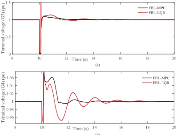
FIGURE 2. Terminal voltages of critical synchronous generators when the
most severe fault is applied at the terminal of G3.
To consistent with the simulation time, it is assumed that all these faults occur at t=10 s and clear at t=10.12 s, i.e., the fault duration is 0.12 s which is considered as a sig-nificantly large fault. The simulations are carried out using MATLAB/SIMULINK SimPowerSystem Toolbox. During the simulations, the physical limit of the excitation voltage is considered as ±5 pu in order to avoid the overvoltage problem in the excitation coil. To get a deeper insight into the controller performance, the designed FBL-MPC is compared with a feedback linearized LQR (FBL-LQR) in [25] under the operating conditions as discussed in the following case studies.
Case 1 (Controller Performance in Case of the Most Severe
Fault at the Terminal of a Synchronous Generator): The
three-phase short-circuit faults at the generator terminal are considered as the most severe faults in power systems which affect the equilibrium between electrical and electromagnetic torque resulting the loss of synchronism among coherent generators as well as requires disconnection of the affected generators from the system. Therefore, the output voltage and power of the affected generator will be zero during the faulted conditions which in turn will influence the speed deviation and rotor angle responses of the generator.
In this case study, the three-phase short-circuit fault is applied at the terminal of G3 and during the faulted condition, the terminal voltage of this generator will be zero as shown in Fig. 2(a). As G3 and G4 are in the coherent generator group, the terminal voltage of G4 will also be affected as shown in Fig.2(b). When the fault is cleared at t=10.12 s, the terminal voltages of G3 and G4 will settle down to their initial values with some oscillations if the excitation controllers with G3 and G4 provide adequate damping. Fig. 2 shows that the designed FBL-MPC provides more damping as com-pared to the FBL-LQR controller and hence, there are less oscillations with the designed controller. Similarly, the speed deviation and rotor angle responses of G3 and G4 in Fig.3
and Fig. 4 show oscillating characteristics during the fault and post-fault conditions. These responses in Fig.3and Fig.4
clearly indicate that the oscillations are sustained for several
FIGURE 3. Speed deviations of critical synchronous generators when the
most severe fault is applied at the terminal of G3.
FIGURE 4. Rotor angles of critical synchronous generators when the most
severe fault is applied at the terminal of G3.
FIGURE 5. Excitation control signals of critical synchronous generators
when the most severe fault is applied at the terminal of G3.
cycles when the FBL-LQR controller is used. However, the oscillations in the speed deviation and rotor angle responses are quickly damped out when the FBL-MPC is used. The characteristics of excitation control signals of G3 and G4 as presented in Fig.5 further justify the superiority of the designed control scheme as these signals are more stable with the designed FBL-MPC while comparing with the FBL-LQR controller.
FIGURE 6. Terminal voltages of critical generators when a severe fault is applied at the middle of the transmission line between bus-16 and bus-19.
FIGURE 7. Speed deviations of critical generators when a severe fault is
applied at the middle of the transmission line between bus-16 and bus-19.
Case 2 (Controller Performance When a Severe Fault Is Applied at the Middle of the Transmission Line Between
Bus-16 and Bus-19):The three-phase short-circuit fault on
one of the transmission line is considered as another serious issue in power systems which can lead to the voltage insta-bility as well as the synchronism discrepancy. In this case study, a three-phase short-circuit fault is applied at the middle of the transmission line between the bus-16 and bus-19 to justify performance of the designed controller. The terminal voltages of both G3 and G4 are nonzero due to this fault and these responses are shown in Fig.6which are deviated from their nominal operating conditions. The designed FBL-MPC shows excellent performance as it steers the terminal voltages to regain their pre-fault values. Similarly, the speed deviation and rotor angle responses of critical generators in Fig.7and Fig.8show that the designed FBL-MPC acts faster in order to damp out the oscillations due to this fault. The excitation control signals of G3 and G4 are shown in Fig.9. From these figures, it can be seen that the designed FBL-MPC controller performs better than the FBL-LQR controller.
Case 3 (Controller Performance When the Transmission
Line Between Bus-15 and Bus-16 Is Temporarily Tripped):In
complex interconnected power systems, severe disturbances
FIGURE 8. Rotor angles of critical generators when a severe fault is
applied at the middle of the transmission line between bus-16 and bus-19.
FIGURE 9. Excitation control signals of critical generators when a severe
fault is applied at the middle of the transmission line between bus-16 and bus-19.
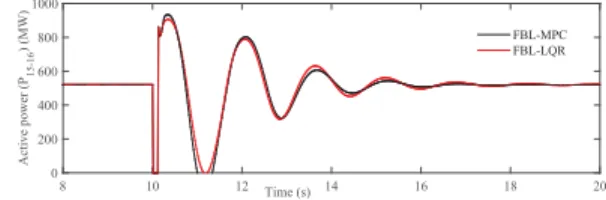
FIGURE 10. Active power flow when the transmission line between
bus-15 and bus-16 is temporarily tripped.
can arise from line tripping especially in long distance bulk power transmission systems. In this case, the transmission line between bus-15 and bus-16 is tripped at t=10 s and reconnected at t=10.12 s in order to evaluate the capability of the designed controller. From Fig.10, it is clear that the active power flow through the transmission line between bus-15 and bus-16 is zero during the tripping period and it regains its pre-fault condition along with some oscillations as the line is reconnected at t=10.12 s. The designed FBL-MPC promptly stabilizes these oscillations as compared to the FBL-LQR controller. Again, the excitation control signals of G3 and G4 are shown in Fig.11which illustrate that the excitation
T. F. Orchiet al.: FBL Model Predictive Excitation Controller Design
FIGURE 11. Excitation control signals when the transmission line
between bus-15 and bus-16 is temporarily tripped.
control signals of the designed controller act in a quicker way to stabilize post-fault disturbances.
From the simulation results, it is clear that the designed controller performs well under different operating conditions securing minimal post-fault oscillations and thus, capable of improving the transient stability of power systems under a wide range of operating conditions.
VI. CONCLUSION
A continuous-time receding horizon-based feedback lineariz-ing model predictive excitation controller is designed for synchronous generators in multimachine power systems. The nonlinear dynamical model of multimachine power systems is augmented into a linear one using the partial feedback linearization approach and the receding horizon model pre-dictive control scheme is then used for the linearized sys-tem. The designed control scheme is more practical, simple, and cost-effective in the sense that it eliminates the use of an observer for measuring the rotor angle. The designed controller is implemented on a large multimachine power system and simulation studies are carried out under different operating scenarios. Simulation results clearly indicate the enhancement of the dynamic stability of the system with the designed controller in terms of providing adequate damping and improved settling time under different operating condi-tions. An extension of this work will deal with the implemen-tation of the proposed control by considering the dynamics of steam-valve systems along with the dynamics of synchronous generators.
APPENDIX THE VALUES OFL3f
i(1ωi),Api,Bpi, ANDCpi
The value ofLf3
i(1ωi) can be calculated as follows:
Lf3 i(1ωi)=[αi(ωi−ω0i)Pei−(αiβi+γi)Qei −γiEfdiIdif1i+(αiQei+βi2)f2i +[αi(ωi−ω0i)Idi+(αiβi+γi)Iqi]f3i +[−αi(ωi−ω0i)Iqi+(αiβi +γi)Idi]f4i−γiIqif5i
The values ofApi,Bpi, andCpi for equation (31) can be
written as follows: Api = 0 1 0 0 0 1 0 0 0 , Bpi = 0 0 1 , andCpi = 1 0 0 T . REFERENCES
[1] C. Canizareset al., ‘‘Benchmark models for the analysis and control of small-signal oscillatory dynamics in power systems,’’IEEE Trans. Power Syst., vol. 32, no. 1, pp. 715–722, Jan. 2017.
[2] F. P. Demello and C. Concordia, ‘‘Concepts of synchronous machine stability as affected by excitation control,’’IEEE Trans. Power App. Syst., vol. PAS-88, no. 4, pp. 316–329, Apr. 1969.
[3] P. Kundur,Power System Stability and Control. New York, NY, USA: McGraw-Hill, 1994.
[4] A. Kumar, ‘‘Power system stabilizers design for multimachine power systems using local measurements,’’IEEE Trans. Power Syst., vol. 31, no. 3, pp. 2163–2171, May 2016.
[5] C. Li, Z. Du, Y. Ni, and G. Zhang, ‘‘Reduced model-based coordinated design of decentralized power system controllers,’’IEEE Trans. Power Syst., vol. 31, no. 3, pp. 2172–2181, May 2016.
[6] M. Bhadu, N. Senroy, I. N. Kar, and G. N. Sudha, ‘‘Robust linear quadratic Gaussian-based discrete mode wide area power system damping con-troller,’’IET Generat., Transmiss. Distrib., vol. 10, no. 6, pp. 1470–1478, Apr. 2016.
[7] H. Lomei, D. Sutanto, K. Muttaqi, and A. Alfi, ‘‘An optimal robust excitation controller design considering the uncertainties in the exciter parameters,’’IEEE Trans. Power Syst., vol. 32, no. 6, pp. 4171–4179, Nov. 2017.
[8] M. Ouassaida, M. Maaroufib, and M. Cherkaouib, ‘‘A real-time nonlinear decentralized control of multimachine power systems,’’Syst. Sci. Control Eng., Open Access J., vol. 2, no. 1, pp. 135–142, 2014.
[9] J. Li, Y. Liu, C. Li, and B. Chu, ‘‘Passivity-based nonlinear excitation con-trol of power systems with structure matrix reassignment,’’Infromation, vol. 4, no. 3, pp. 342–350, 2013.
[10] S. S. Majidabad, H. T. Shandiz, and A. Hajizadeh, ‘‘Nonlinear fractional-order power system stabilizer for multi-machine power systems based on sliding mode technique,’’Int. J. Robust Nonlinear Control, vol. 25, no. 10, pp. 1548–1568, 2015.
[11] X. Liu and Y. Han, ‘‘Decentralized multi-machine power system excita-tion control using continuous higher-order sliding mode technique,’’Int. J. Elect. Power Energy Syst., vol. 82, pp. 76–86, Nov. 2016.
[12] M. Mohamed, X.-G. Yan, S. K. Spurgeon, and B. Jiang, ‘‘Robust sliding-mode observers for large-scale systems with application to a multimachine power system,’’IET Control Theory Appl., vol. 11, no. 8, pp. 1307–1315, 2017.
[13] T. K. Roy, M. A. Mahmud, W. Shen, A. M. T. Oo, and M. E. Haque, ‘‘Robust nonlinear adaptive backstepping excitation controller design for rejecting external disturbances in multimachine power systems,’’ Int. J. Elect. Power Energy Syst., vol. 84, pp. 76–86, Jan. 2017.
[14] R. Huang, J. Zhang, and Z. Lin, ‘‘Decentralized adaptive controller design for large-scale power systems,’’Automatica, vol. 79, pp. 93–100, May 2017.
[15] T. K. Roy, M. A. Mahmud, W. Shen, and A. M. T. Oo, ‘‘Nonlinear adaptive excitation controller design for multimachine power systems with unknown stability sensitive parameters,’’IEEE Trans. Control Syst. Technol., vol. 25, no. 6, pp. 2060–2072, Nov. 2017.
[16] Y. Zheng, J. Zhou, W. Zhu, C. Zhang, C. Li, and W. Fu, ‘‘Design of a multi-mode intelligent model predictive control strategy for hydroelectric generating unit,’’Neurocomputing, vol. 207, pp. 287–299, Sep. 2016. [17] W. Yao, L. Jiang, J. Fang, J. Wen, and S. Cheng, ‘‘Decentralized nonlinear
optimal predictive excitation control for multi-machine power systems,’’ Int. J. Electr. Power Energy Syst., vol. 55, pp. 620–627, Feb. 2014. [18] A. E. Leon, J. A. Solsona, and M. I. Valla, ‘‘Comparison among nonlinear
excitation control strategies used for damping power system oscillations,’’ Energy Convers. Manage., vol. 53, no. 1, pp. 55–67, 2012.
[19] C. A. King, J. W. Chapman, and M. D. Ilic, ‘‘Feedback linearizing excita-tion control on a full-scale power system model,’’IEEE Trans. Power Syst., vol. 9, no. 2, pp. 1102–1109, May 1994.
[20] M. A. Mahmud, H. R. Pota, and M. J. Hossain, ‘‘Full-order nonlinear observer-based excitation controller design for interconnected power sys-tems via exact linearization approach,’’Int. J. Electr. Power Energy Syst., vol. 41, no. 1, pp. 54–62, 2012.
[21] G. Kenné, R. Goma, H. Nkwawo, F. Lamnabhi-Lagarrigue, A. Arzandé, and J. C. Vannier, ‘‘An improved direct feedback linearization technique for transient stability enhancement and voltage regulation of power gener-ators,’’Int. J. Elect. Power Energy Syst., vol. 32, no. 7, pp. 809–816, 2010. [22] B. Fan, Q. Yang, K. Wang, J. Xu, and Y. Sun, ‘‘Transient stability enhancement control of power systems with time-varying constraints,’’IET Generat., Transmiss. Distrib., vol. 10, no. 13, pp. 3251–3263, 2016. [23] M. A. Mahmud, H. R. Pota, M. Aldeen, and M. J. Hossain, ‘‘Partial
feedback linearizing excitation controller for multimachine power systems to improve transient stability,’’IEEE Trans. Power Syst., vol. 29, no. 2, pp. 561–571, Mar. 2014.
[24] Y. Wan and F. Milano, ‘‘Nonlinear adaptive excitation control for structure preserving power systems,’’IEEE Trans. Power Syst., to be published, doi: 10.1109/TPWRS.2017.2752764.
[25] M. A. Mahmud, M. J. Hossain, H. R. Pota, and A. M. T. Oo, ‘‘Robust partial feedback linearizing excitation controller design for multimachine power systems,’’IEEE Trans. Power Syst., vol. 32, no. 1, pp. 3–16, Jan. 2017. [26] Y. N. Lu,Electric Power System Dynamics. London, U.K.: Academic,
1983.
[27] A. Varghese, P. W. Sauer, and M. A. Pai, ‘‘Synchronous machine block diagram analysis with fast dynamics,’’Int. J. Elect. Power Energy Syst., vol. 11, no. 4, pp. 239–247, Oct. 1989.
[28] P. W. Sauer and M. A. Pai, Power System Dynamics and Stability. Englewood Cliffs, NJ, USA: Prentice-Hall, 1997.
[29] J. R. Winkelman, J. H. Chow, J. J. Allemong, and P. V. Kokotovic, ‘‘Multi-time-scale analysis of a power system,’’Automatica, vol. 16, no. 1, pp. 35–43, 1980.
[30] S. Ahmed-Zaid, P. W. Sauer, J. R. Winkelman, ‘‘Higher order dynamic equivalents for power systems,’’Automatica, vol. 22, no. 4, pp. 489–494, 1986.
[31] M. A. Pai, P. W. Sauer, and B. C. Lesieutre, ‘‘Static and dynamic nonlinear loads and structural stability in power systems,’’Proc. IEEE, vol. 83, no. 11, pp. 1562–1572, Nov. 1995.
[32] R. A. Ramos, L. F. C. Alberto, and N. G. Bretas, ‘‘A new methodology for the coordinated design of robust decentralized power system damping con-trollers,’’IEEE Trans. Power Syst., vol. 19, no. 1, pp. 444–454, Feb. 2004. [33] A. Isidori, Nonlinear Control Systems, 2nd ed.. Berlin, Germany:
Springer-Verlag, 1989.
[34] Q. Lu, Y. Sun, Z. Xu, and T. Mochizuki, ‘‘Decentralized nonlinear optimal excitation control,’’IEEE Trans. Power Syst., vol. 11, no. 4, pp. 1957–1962, Nov. 1996.
[35] L. Wang,Model Predictive Control System Design and Implementation Using MATLAB. London, U.K.: Springer-Verlag, 2009.
[36] M. A. Pai,Energy Function Analysis for Power System Stability. Boston, MA, USA: Kluwer, 1989.
T. F. ORCHIreceived the bachelor’s degree in electrical engineering from RUET in 2009 and the master’s degree in electrical engineering from The University of New South Wales, Australia, in 2013. She is currently pursuing the Ph.D. degree with Deakin University.
Her research interests include nonlinear control, power systems, and renewable energies.
T. K. ROYreceived the bachelor’s degree in electrical engineering from RUET in 2008 and the master’s degree in electrical engineering from The University of New South Wales, Australia, in 2012. He is currently pursuing the Ph.D. degree with Deakin University.
His research interests include nonlinear adaptive backstepping control, power systems, and renewable energies.
M. A. MAHMUDreceived the bachelor’s degree in electrical engineering from RUET in 2008 and the Ph.D. degree in electrical engineering from The University of New South Wales, Australia, in 2012. He was a Lecturer in electrical and electronic engineering with the Swinburne University of Technology, a Research Fellow with The University of Melbourne, and a Research Publication Fellow with The University of New South Wales. He is currently a Lecturer in electrical and renewable energy engineering with Deakin University, Australia. He received the Best Thesis Award from The University of New South Wales.
His research interests include different aspects of microgrids, power system stability and control, and nonlinear control theories.
AMANULLAH M. T. OOreceived the master’s degree in electrical engi-neering from The University of Melbourne, Australia, and the Ph.D. degree in electrical engineering from Victoria University, Australia. He is currently the Deputy Head of the School of Engineering, Deakin University, where he leads school teaching and learning matters. He is also the Head of the Electrical and Electronics Engineering Discipline at Deakin University.
His research interests and expertise include renewable energy and energy storage system integration, smart grid communication, power system stabil-ity and control, energy management and efficiencies, protection and securstabil-ity of smart grids, sustainable operation and control of microgrids.
![FIGURE 1. The IEEE 39-bus 10-machine New England power system [36].](https://thumb-us.123doks.com/thumbv2/123dok_us/9023036.2800167/7.864.454.795.89.425/figure-ieee-bus-machine-new-england-power.webp)