and Mobile Network Virtualization
submitted to the
Faculty of Physics and Electrical Engineering,
University of Bremen
for obtainment of the academic degree
Doktor-Ingenieur (Dr.-Ing.)
Dissertation
by
Yasir Zaki, M.Sc. B.Sc.
from Baghdad, Iraq
First assessor: Prof. Dr. rer. nat. habil. Carmelita Görg
Second assessor: Prof. Dr. Samir R. Das
Submission date: 7th of May 2012
University of Bremen. The literature used is listed completely in the bibliography.
Bremen, 7th of May 2012
I would like to dedicate this Doctoral dissertation to my beloved wife Tamara Hamed, for her unconditional support and great patience at all times. I will fo-rever owe her a debt of gratitude, for always believing in me, even in the times when I didn’t. I would also like to thank my parents, who have given me their un-equivalent support throughout, as always, for which my mere expression of thanks likewise does not suffice. Special dedication to my beloved kids Tanya and Yezin.
It would not have been possible to finish this work, and write the thesis without the help and support of all the kind people around me, to only some of whom it is possible to give particular mention here.
This thesis would not have seen the light without the help, support and patience of my supervisor, Prof. Dr. Carmelita Görg. Her wide knowledge, encouragement and personal guidance have been of great value to me. I would also like to express my gratitude to Prof. Dr.-Ing. Andreas Timm-Giel, for all his support and valuable input.
The good advice, support and friendship of my colleague, Dr. Thushara Weera-wardane, has been invaluable on both academic and personal level, for which I am extremely grateful. During this work I have collaborated with many colleagues for whom I have great respect, in particular I wish to extend my warmest thanks to Dr. Koojana Kuladinithi and Asanga Udugama, for providing all the great family oriented activities. I would also like to express my gratitude to Dr. Hadeer Hamed and Mr. Khalis Mahmoud Khalis, for their great support in revising the thesis.
I would like to acknowledge all of my friends and colleagues within the Com-Nets department, of the University of Bremen, for their support and help that kept me stay sane, through these difficult years. Dr. Xi Li, for her help in proof rea-ding of the thesis, Liang Zhao, for being a great work partner throughout all the projects we worked together. I would also like to thank Dr. Andreas Könsgen and Markus Becker, for offering their Linux expertise. Lots of gratitude to Umar To-seef, Muhammed Mutakin Siddique, Aman Singh, Dr. Bernd-Ludwig Wenning, Martina Kamman and Karl-Heinz Volk, for their support. In addition, I would also like to thank my students Nikola Zahariev and Safdar Nawaz Khan Marwat for their support and good work.
Finally, a special acknowledgment, for the DAAD (German Academic Exchange Service), for giving me the chance to come to Germany, to do my Master studies, which lead eventually, to the finishing of my doctoral studies.
Providing QoS while optimizing the LTE network in a cost efficient manner is very challenging. Thus, radio scheduling is one of the most important functions in mobile broadband networks. The design of a mobile network radio scheduler holds several objectives that need to be satisfied, for example: the scheduler needs to maximize the radio performance by efficiently distributing the limited radio re-sources, since the operator’s revenue depends on it. In addition, the scheduler has to guarantee the user’s demands in terms of their Quality of Service (QoS). Thus, the design of an effective scheduler is rather a complex task. In this thesis, the au-thor proposes the design of a radio scheduler that is optimized towards QoS guar-antees and system performance optimization. The proposed scheduler is called “Optimized Service Aware Scheduler” (OSA). The OSA scheduler is tested and analyzed in several scenarios, and is compared against other well-known sched-ulers.
A novel wireless network virtualization framework is also proposed in this the-sis. The framework targets the concepts of wireless virtualization applied within the 3GPP Long Term Evolution (LTE) system. LTE represents one of the new mo-bile communication systems that is just entering the market. Therefore, LTE was chosen as a case study to demonstrate the proposed wireless virtualization frame-work. The framework is implemented in the LTE network simulator and analyzed, highlighting the many advantages and potential gain that the virtualization process can achieve. Two potential gain scenarios that can result from using network virtu-alization in LTE systems are analyzed: Multiplexing gain coming from spectrum sharing, and multi-user diversity gain.
Several LTE radio analytical models, based on Continuous Time Markov Chains (CTMC) are designed and developed in this thesis. These models target the model-ing of three different time domain radio schedulers: Maximum Throughput (MaxT), Blind Equal Throughput (BET), and Optimized Service Aware Scheduler (OSA). The models are used to obtain faster results (i.e., in a very short time period in the order of seconds to minutes), compared to the simulation results that can take con-siderably longer periods, such as hours or sometimes even days. The model results are also compared against the simulation results, and it is shown that it provides a
good match. Thus, it can be used for fast radio dimensioning purposes.
Overall, the concepts, investigations, and the analytical models presented in this thesis can help mobile network operators to optimize their radio network and pro-vide the necessary means to support services QoS differentiations and guarantees. In addition, the network virtualization concepts provides an excellent tool that can enable the operators to share their resources and reduce their cost, as well as pro-vides good chances for smaller operators to enter the market.
Die Bereitstellung von Dienstgüte (Quality of Service, QoS) bei der Optimie-rung von LTE-Netzen ist eine große HerausfordeOptimie-rung. Daher ist das Scheduling auf der Funkschnittstelle eine der wichtigsten Funktionen in mobilen Breitband-netzen. Der Entwurf eines Schedulers für mobile Funknetze beinhaltet verschiede-ne Kriterien, die erfüllt werden müssen, beispielsweise soll der Scheduler das Leis-tungsverhalten auf der Funkschnittstelle durch effiziente Verteilung der begrenz-ten Funkressourcen maximieren, da hiervon der Ertrag des Betreibers abhängt. Zusätzlich muss der Scheduler die Nutzeranforderungen bgzl. ihrer Dienstgüte garantieren. Aus diesem Grund ist der Entwurf eines effektiven Schedulers ein durchaus komplexer Prozess. In dieser Arbeit schlägt der Autor einen Scheduler für die Funkschnittstelle vor, der für Dienstgütegarantien und die Optimierung des Systemleistungsverhaltens ausgelegt ist. Der vorgestellte Scheduler trägt die Be-zeichnung “Optimierter dienstgütesensitiver Scheduler, Optimized Service Aware Scheduler (OSA)”. Der OSA-Scheduler wird in verschiedenen Szenarien getestet und analysiert sowie mit anderen gut bekannten Schedulern verglichen.
Ein neuartiges Framework zur Virtualisierung drahtloser Netze wird in dieser Arbeit ebenfalls vorgeschlagen. Das Framework zielt auf die Konzepte der draht-losen Virtualisierung ab, die innerhalb des 3GPP Long Term Evolution-Systems angewendet werden. LTE repräsentiert eines der neuen mobilen Kommunikations-systeme, die gegenwärtig in den Markt eintreten. Daher wurde LTE als Fallstudie ausgewählt, um das vorgeschlagene drahtlose Virtualisierungs-Framework zu de-monstrieren. Das Framework wird im LTE-Netzsimulator implementiert und ana-lysiert, wobei die zahlreichen Vorteile und der mögliche Zugewinn herausgestellt wird, den der Virtualsierungsprozess erzielen kann. Zwei mögliche Szenarien, die sich aus der Nutzung der Netzvirtualisierung ergeben und Zugewinn erzielen können, werden analysiert: Multiplexing-Gewinn, der sich aus der Aufteilung des Spektrums ergibt, und Diversitätsgewinn zwischen mehreren Benutzern.
Verschiedene analytische Modelle für LTE-Funknetze, basierend auf zeitkon-tinuierlichen Markov-Ketten (Continuous Time Markov Chains, CMTC), werden in dieser Arbeit entworfen und entwickelt. Diese Modelle zielen auf die Untersu-chung drei verschiedener Scheduler für die Funkschnittstelle ab, die in der
zeit-lichen Domäne arbeiten: maximaler Durchsatz (Maximum Throughput, MaxT), blinder Scheduler mit gleichverteiltem Durchsatz (Blind Equal Throughput, BET) und optimierter dienstgütesensitiver Scheduler (Optimised Service Aware Sche-duler, OSA). Die Modelle werden verwendet, um schneller Ergebnisse zu erzielen (d.h. in einer sehr kurzen zeitlichen Periode in der Größenordnung Sekunden bis Minuten), verglichen mit Simulationen, die deutlich längere zeitliche Perioden be-anspruchen, wie Stunden oder manchmal sogar Tage. Die Ergebnisse des Modells werden auch mit den Simulationsergebnissen verglichen, und es wird gezeigt, dass sie gut übereinstimmen. Daher können sie zum Zweck einer schnellen Dimensio-nierung der Funkschnittstelle eingesetzt werden.
Insgesamt können die Konzepte, Untersuchungen und die analytischen Model-le, die in dieser Arbeit vorgestellt werden, den Betreibern mobiler Netze helfen, ihr Funknetz zu optimieren und die notwendigen Mittel für die Unterstützung von Dienstgütedifferenzierung und -garantien bereitzustellen. Zusätzlich bilden die Konzepte der Netzvirtualisierung ein hervorragendes Werkzeug, das es den Be-treibern ermöglicht, Ressourcen zu teilen und Kosten zu reduzieren, was auch kleineren Providern den Markteintritt ermöglicht.
Abstract IX
Kurzfassung XI
List of Figures XVII
List of Tables XXI
List of Abbreviations XXIII
List of Symbols XXVII
1 Introduction 1
2 Mobile Communication Systems 5
2.1 Global System for Mobile Communication (GSM) . . . 6
2.2 Universal Mobile Telecommunication System (UMTS) . . . 9
3 Long Term Evolution (LTE) 13 3.1 Motivation and Targets . . . 13
3.2 LTE Multiple Access Schemes . . . 14
3.2.1 OFDM . . . 14
3.2.2 OFDMA . . . 15
3.2.3 SC-FDMA . . . 16
3.3 LTE Network Architecture . . . 17
3.3.1 User Equipment (UE) . . . 18
3.3.2 Evolved UTRAN (E-UTRAN) . . . 18
3.3.3 Evolved Packet Core (EPC) . . . 19
3.4 E-UTRAN Protocol Architecture . . . 20
3.4.1 Radio Link Control (RLC) . . . 23
3.4.2 Medium Access Control (MAC) . . . 24
3.4.2.2 HARQ . . . 25
3.4.2.3 Scheduling . . . 26
3.4.3 LTE Frame and Physical Resource Structure . . . 27
3.5 LTE Quality of Service Bearers . . . 28
3.6 Beyond LTE . . . 30
3.6.1 Wider Bandwidth for Transmission . . . 31
3.6.2 Advanced MIMO Solutions . . . 31
3.6.3 CoMP . . . 32
3.6.4 Relays and Repeaters . . . 32
4 LTE Network Simulator 35 4.1 Simulation Environment . . . 35
4.2 Simulation Framework . . . 36
4.3 Simulation Model . . . 37
4.3.1 UE Node Model . . . 38
4.3.2 eNodeB Node Model . . . 39
4.3.3 Access Gateway Node Model . . . 40
4.3.4 Packet Data Network Gateway Node Model . . . 40
4.3.5 Mobility and Channel Node . . . 41
4.3.6 Global User Database . . . 44
4.3.7 Application Configuration . . . 44
4.3.8 Profile Configuration . . . 44
4.4 Traffic Models . . . 45
4.4.1 Voice over IP Model (VoIP) . . . 46
4.4.2 Web Browsing Model . . . 47
4.4.3 Video Streaming Model . . . 48
4.4.4 File Transfer Model . . . 49
4.5 Statistical Evaluation . . . 49
4.5.1 Confidence Interval Estimation . . . 49
4.5.2 Independent Replications Method . . . 50
5 LTE Virtualization 53 5.1 Virtualization . . . 53
5.1.1 Server Virtualization . . . 54
5.1.2 Network Virtualization . . . 56
5.2 4WARD Project . . . 57
5.2.1 4WARD Virtualization Paradigm . . . 57
5.3 Wireless Virtualization in Mobile Communication . . . 59
5.3.2 LTE Virtualization Framework . . . 61
5.3.2.1 Framework Architecture . . . 62
5.3.2.2 LTE Hypervisor Algorithm . . . 63
5.3.2.3 Operator Bandwidth Estimation . . . 64
5.3.2.4 Contract based Framework . . . 65
5.4 LTE Virtualization Evaluation . . . 68
5.4.1 Multiplexing Gain based Analysis . . . 69
5.4.2 Multi-User Diversity Gain based Analysis . . . 73
5.4.3 Contract Based Framework based Analysis . . . 76
5.5 Conclusion . . . 83
6 LTE Radio Scheduler 85 6.1 LTE Dynamic Packet Scheduling . . . 86
6.2 LTE MAC Schedulers State of the Art . . . 87
6.2.1 Classical Scheduling Algorithms . . . 87
6.3 Downlink MAC Scheduler Design . . . 89
6.3.1 QCI Classification . . . 90
6.3.2 Time Domain Scheduler (TDS) . . . 91
6.3.3 Frequency Domain Scheduler (FDS) . . . 94
6.3.4 Link-to-System Mapping (L2S) . . . 96
6.3.5 HARQ Modeling . . . 98
6.4 Downlink MAC Scheduler Analysis . . . 99
6.4.1 OSA vs. Classical Schedulers . . . 99
6.4.1.1 FTP only scenario . . . 100
6.4.1.2 Mixed traffic scenario . . . 104
6.4.2 GBR delay Exploitation . . . 108
6.5 Conclusion . . . 112
7 Analytical Modeling of the LTE Radio Scheduler 113 7.1 General Analytical Model . . . 114
7.1.1 Performance Evaluation . . . 115
7.1.2 Generic Departure Rate . . . 117
7.2 LTE Downlink Scheduler Modeling . . . 120
7.2.1 Single Class Model . . . 120
7.2.2 Single Class Model Results . . . 124
7.2.2.1 Analysis 1 - MaxT . . . 125
7.2.2.2 Analysis 2 - BET . . . 129
7.2.2.3 Analysis 3 - Sensitivity Analysis . . . 132
7.2.2.5 Analysis 5 - BET with Random Direction (RD) 134
7.2.3 Two Dimensional Model . . . 136
7.2.3.1 2D TDS Modeling . . . 138
7.2.3.2 2D Performance Analysis . . . 139
7.2.4 Two Dimensional Model Results . . . 141
7.2.4.1 Analysis - w-MaxT . . . 142
7.2.4.2 Analysis - w-BET . . . 146
7.2.4.3 Analysis - OSA . . . 150
7.3 Conclusion . . . 151
8 Conclusions and Outlook 153 A Appendix 159 A.1 Mobility Models . . . 159
A.2 3GPP Transport Block Size . . . 161
A.3 Simulation Results Confidence Interval . . . 162
2.1 3GPP releases overview [HT09] [Zah11] . . . 6
2.2 GSM network Architecture 1 . . . 7
2.3 GSM system evolution . . . 9
2.4 UMTS network Architecture1 . . . 10
3.1 LTE EPS network architecture . . . 13
3.2 OFDM signal in frequency and time domain [Hoa05] . . . 15
3.3 An example of channel dependent scheduling between two users [ADF+09] . . . 16
3.4 An example comparing SC-FDMA to OFDMA [Agi09] . . . 17
3.5 LTE E-UTRAN architecture . . . 19
3.6 LTE E-UTRAN user plane protocol stack . . . 20
3.7 Detailed LTE downlink protocol architecture [Dah07] . . . 22
3.8 Multiple parallel HARQ processes example [Dah07] . . . 26
3.9 LTE FDD frame structure [Anr09] . . . 27
3.10 Relationship between slot, symbol and Resource Blocks [Anr09] . 28 3.11 SAE bearer model [HT09] . . . 29
3.12 LTE-advanced CoMP . . . 32
3.13 LTE-advanced in-band relay and backhaul [Agi11] . . . 33
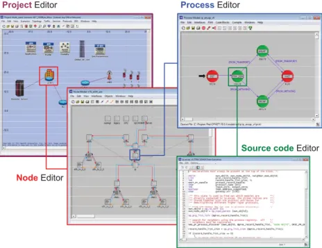
4.1 OPNET Modeler© hierarchical editors . . . 35
4.2 LTE reference model . . . 36
4.3 LTE OPNET simulation model . . . 37
4.4 UE Node Model . . . 38
4.5 eNodeB Node Model . . . 39
4.6 aGW Node Model . . . 40
4.7 PDN-GW Node Model . . . 41
4.8 An example result of the fast fading model . . . 43
4.9 Sample OPNET application configuration . . . 45
4.10 Sample OPNET profile configuration . . . 45
4.12 VoIP MOS values [IT09] . . . 47
4.13 Web traffic model . . . 47
5.1 Full virtualization environment [Cha09] . . . 55
5.2 Para virtualization environment [Cha09] . . . 55
5.3 OS-virtualization environment [Cha09] . . . 56
5.4 Network Virtualization Proposed Business Model . . . 58
5.5 Multiple Access Schemes . . . 60
5.6 LTE virtualization framework architecture . . . 63
5.7 The general hypervisor algorithm framework . . . 67
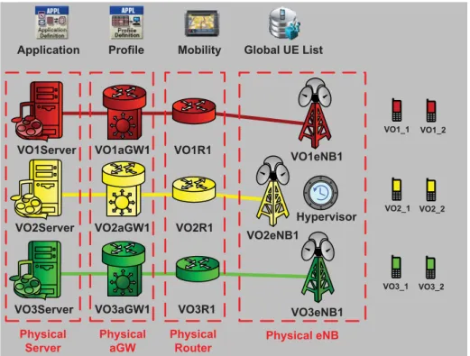
5.8 LTE virtualization simulation model in OPNET . . . 69
5.9 Virtual operators allocated bandwidth over simulation time . . . . 71
5.10 Virtual Operator 1 VoIP air interface throughput . . . 72
5.11 Virtual Operator 1 VoIP application end-to-end delay . . . 72
5.12 Virtual Operator 1 VoIP application end-to-end delay . . . 73
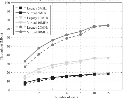
5.13 Virtual Operator 1 cell throughput with and without virtualization 75 5.14 Virtual Operator 1 cell throughput gain due to virtualization . . . . 76
5.15 Virtual Operator allocated bandwidth/PRBs) . . . 78
5.16 Virtual Operator 1 Video downlink application end-to-end delay . 79 5.17 Virtual Operator 2 Video downlink application end-to-end delay . 80 5.18 Virtual Operator 2 downlink allocated bandwidth . . . 80
5.19 Virtual Operator 3 Video downlink application end-to-end delay . 81 5.20 Virtual Operator 3 average FTP download time . . . 82
5.21 Virtual Operator 3 average number of FTP Files downloaded . . . 82
5.22 Virtual Operator 4 VoIP downlink application end-to-end delay . . 83
6.1 General packet scheduling framework [HT09] . . . 86
6.2 OSA general scheduler framework . . . 90
6.3 FDS general flow chart . . . 95
6.4 Reference BLER versus SINR AWGN curves . . . 96
6.5 Average user FTP download time . . . 101
6.6 Unfairness between users FTP download time . . . 102
6.7 Average cell throughput comparison . . . 103
6.8 40 UE scenario - scheduler comparison . . . 104
6.9 Application delay performance comparison between schedulers . . 106
6.10 Fairness and cell throughput comparison between schedulers . . . 107
6.11 Average cell throughput . . . 109
6.12 Average VoIP application end-to-end delay . . . 110
6.14 non-GBR services performance comparison spider chart . . . 111
7.1 General Continuous Time Markov Chain . . . 114
7.2 MaxT scheduling of users (example with 7 MCSs) . . . 122
7.3 BET scheduling of users (example with 7 MCSs) . . . 122
7.4 MCSs static probability obtained from simulations . . . 123
7.5 OSA scheduling of users (example with 7 MCSs) . . . 124
7.6 MaxT 10UEs scenario - average FTP download time . . . 126
7.7 MaxT 20UEs scenario - average FTP download time . . . 127
7.8 MaxT Markov chain state probability . . . 128
7.9 BET 10UEs scenario - average FTP download time . . . 129
7.10 BET 20UEs scenario - average FTP download time . . . 130
7.11 BET Markov chain state probability . . . 131
7.12 MaxT sensitivity analysis results . . . 132
7.13 OSA 10UEs scenario - average FTP download time . . . 133
7.14 OSA Markov chain state probability . . . 134
7.15 BET RD 10UEs scenario - average FTP download time . . . 135
7.16 Two dimensional Markov chain . . . 136
7.17 2D Markov chain represented in a single chain . . . 139
7.18 Example Q mapping with N1=2 and N2=4 . . . 139
7.19 Analysis1 w-MaxT average FTP download time . . . 142
7.20 Analysis2 w-MaxT average FTP download time . . . 143
7.21 Analysis1 w-MaxT Markov chain state probability . . . 144
7.22 Analysis2 w-MaxT Markov chain state probability . . . 145
7.23 Analysis3 w-BET average FTP download time . . . 146
7.24 Analysis3 w-BET Markov chain state probability . . . 147
7.25 Analysis4 w-BET average FTP download time . . . 148
7.26 Analysis4 w-BET Markov chain state probability . . . 149
7.27 Analysis5 OSA average FTP download time . . . 150
A.1 Random Way Point (RWP) mobility model . . . 159
3.1 LTE MAC logical channels [36.11b] . . . 25
3.2 LTE MAC transport channels [36.11b] . . . 25
3.3 LTE standardized QCIs and their parameters [SBT09] . . . 30
3.4 System performance comparison [Nak09] . . . 31
4.1 VoIP traffic model parameters [Li10] . . . 46
4.2 Web browsing traffic model parameters [Wee11] . . . 48
5.1 Scenario I simulation configurations . . . 70
5.2 Scenario II simulation configurations . . . 74
5.3 Scenario III simulation configurations . . . 77
6.1 DSCP/QCI to MAC-QoS-Class mapping example . . . 91
6.2 An example of QoS weight values for different non-GBR services 93 6.3 β values for each MCS [KSW+08][LV08a][Val06] . . . 98
6.4 BLER and HARQ transmissions . . . 99
6.5 Simulation configurations . . . 100
6.6 Simulation configurations . . . 105
6.7 Simulation configurations . . . 108
7.1 n=2, K=2 combinations example . . . 119
7.2 Single class validation general parameters . . . 124
7.3 Single class validation scenarios . . . 125
7.4 2-D model validation general parameters . . . 141
7.5 2-D model validation scenarios . . . 141
A.1 3GPP transport block size table (subset) . . . 161
A.2 Analysis 1 - MaxT 10 UEs simulation results confidence interval . 162 A.3 Analysis 1 - MaxT 20 UEs simulation results confidence interval . 162 A.4 Analysis 2 - BET 10 UEs simulation results confidence interval . . 162
A.6 Analysis 3 - BET sensitivity analysis simulation results confidence
interval . . . 162
A.7 Analysis 4 - OSA simulation results confidence interval . . . 163 A.8 Analysis 5 - BET RD simulation results confidence interval . . . . 163 A.9 Analysis 1 - w-MaxT simulation results confidence interval . . . . 163 A.10 Analysis 2 - w-MaxT simulation results confidence interval . . . . 163
A.11 Analysis 3 - w-BET simulation results confidence interval . . . . 163
3GPP 3rd Generation Partnership Project
AMC Adaptive Modulation and Coding
AODV Ad-hoc On-demand Distance Vector
ARP Allocation and Retention Priority
ARQ Automatic Repeat Request
AUC Authentication Center
AWGN Additive White Gaussian Noise
BET Blind Equal Throughput
BLER Block Error Rate
BSC Base Station Controller
BSS Base Station Subsystem
BTS Base Transceiver Station
CA Carrier Aggregation
CDMA Code Division Multiple Access
CN Core Network
CoMP Coordinated Multi-Point
CQI Channel Quality Indicator
CTMC Continuous Time Markov Chain
DeNB Donor eNodeB
DL Downlink
DSCP Differentiated Services Code Point
DVB Digital Video Broadcasting
eNodeB enhanced NodeB
E-UTRAN Evolved Universal Terrestrial Radio Access Network
EDGE Enhanced Data for GSM Evolution
EESM Exponential Effective SINR Mapping
EFR Enhanced Full Rate
EMA Exponential Moving Average
EPC Evolved Packet Core
EPS Evolved Packet System
FDD Frequency Division Duplex
FDM Frequency Domain Multiplexing
FDMA Frequency Division Multiple Access
FDS Frequency Domain Scheduler
FTP File Transfer Protocol
GBR Guaranteed Bit Rate
GMSK Gaussian Minimum Shift Keying
GPRS General Packet Radio Service
GSM Global System for Mobile Communication
HARQ Hybrid Automatic Repeat Request
HLR Home Location Registry
HSDPA High Speed Downlink Packet Access
HSPA High Speed Packet Access
HSS Home Subscriber Server
HSUPA High Speed Uplink Packet Access
HTTP Hypertext Transfer Protocol
IMU International Mobile Telecommunication
IP Internet Protocol
ISP Internet Service Provider
IT Information Technology
ITU International
Telecommunication Union
LTE Long Term Evolution
MAC Medium Access Channel
MaxT Maximum Throughput
MCS Modulation and Coding Scheme
MIESM Mutual Information Effective SINR Mapping
MIMO Multi Input Multi Output
MME Mobility Management Entity
MOS Mean Opinion Score
MS Mobile Station
MSC Mobile Switching Center
non-GBR non-Guaranteed Bit Rate
OFDMA Orthogonal Frequency Domain Multiple Access
OS Operating System
OSA Optimized Service Aware
PCRF Policy and Charging Rules Function
PDA Personal Digital Assistant
PDCP Packet Data Convergence Protocol
PDN Packet Data Network
PDN-GW Packet Data Network Gateway
PDU Protocol Data Unit
PHY Physical Layer
PRB Physical Resource Block
PRBs Physical Resource Blocks
PSK Phase Shift Keying
PSTN Public Switched Telephone Network
QCI QoS Class Identifier
QoS Quality of Service
RD Random Direction
RLC Radio Link Control
RN Relay Node
RNC Radio Network Controller
RRC Radio Resource Control
RWP Random Way Point
S-GW Serving Gateway
SAE System Architecture Evolution
SAN Storage Area Network
SC-FDMA Single Carrier Frequency Domain Multiple Access
SDMA Space Division Multiple Access
SDR Software Defined Radio
SIM Subscriber Identity Module
SINR Signal to Interference Noise Ratio
TBS Transport Block Size
TDMA Time Division Multiple Access
TE Terminal Equipment
TTI Transmission Time Interval
UE User Equipment
UL Uplink
UML User Mode Linux
UMTS Universal Mobile
Telecommunication System
USIM User Service Identity Module
UTRAN UMTS Terrestrial Radio Access Network
VLR Visitor Location Registry
VM Virtual Machine
VMM Virtual Machine Monitor
VNet Virtual Network
VNOs Virtual Network Operators
VoIP Voice over Internet Protocol
WCDMA Wideband Code Division Multiple Access
Symbol Meaning
α smoothing factor
β MCS scaling factor
γk[t] normalized average channel condition of bearer k
δ2 variance
η actual number of users served per TTI
θmax maximum achieved throughput if all PRBs are used under
perfect channel conditions
θk[t] instantaneous achieved throughput for bearer k
θk[t] normalized average throughout of bearer k
λ arrival rate (file inter-arrival time)
μ(n) generic departure rate of state n
π(n) state n steady state probability
πππ Markov chain steady state probability vector
τ smoothing factor
ψ maximum number of users served per TTI
BLEP([γk]) instantaneous Block Error Probability for channel stateγk
BLEP([γe f f]) instantaneous Block Error Probability for channel stateγe f f
D mean number of departures by unit time
Etotal total BE PRB estimate over all BE operators
E(N) average required PRBs at the Nth TTI
Fi operator i fairness factor
HOLdelayk head-of-line packet delay for bearer k K Number of MCSs
MCSk kth modulation and coding scheme n Number of active users per TTI
nk number of users inMCSk
N Number of users in the system
N0 thermal noise (dB)
Symbol Meaning
Pk MCSk static probability
PL path loss (dB)
Ptx eNodeB transmission power per PRB (dBm)
PkBET(t) BET scheduler time domain priority factor for bearer k
PkGBR(t) time domain GBR priority metric of bearer k
PkMaxT(t) MaxT scheduler time domain priority factor for user k
PknonGBR(t) time domain non-GBR priority metric of bearer k
Pkw−BET(t) weighted BET scheduler time domain priority factor for user k
Pkw−MaxT(t) weighted MaxT scheduler time domain priority factor for user k
PRBsAlloci operator i allocated number of PRBs
PRBsT T I(N) instantaneous PRB count at the NthTTI Q Markov chain infinitesimal generator matrix
Q mean number of users
R distance between UE and eNodeB (km)
S(nδ) slow fading at pointnδ (dB)
SINRe f f effective SINR mapping
SINRk[t] instantaneous SINR value of bearer k
SINRi,j Signal to Interference Noise Ratio onPRBi)for user j (dB)
SINRmax scaling factor (maximum achieved SINR)
t(α/2,N−1) upper critical value of the t-distribution with N-1 degrees of freedom
to f f traffic model average OFF duration
ton average ON duration (file download time) Tavg average download time of all users
Ti per-user average download time
T BSk(η) number of bits that can be transmitted by a served UE usingMCSk T BS(n) state n average number of bits transmitted within a TTI
T BS(n0,...,nk) total bits transmitted for all served users under combination(n0,...,nk)
UF% Unfairness factor (%)
Vi i.i.d. normal random variable
WQoSj QoS weight of the jthMAC QoS class
x sample mean
Xc de-correlation distance (m)
Xk,i scheduler decision whether a UE is served or not (1 or 0)
Xon traffic model average file size
Long Term Evolution (LTE) is one of the latest releases of the Third Mobile Gener-ation Partnership Project (3GPP). The idea behind standardizing LTE was to create a system that can surpass the older mobile standards (e.g., UMTS and HSPA), and stay competitive at least for the next 10 years. One of the main features of LTE is that it has a flat and IP packet based architecture. In addition, LTE standards define a new air interface that is based on the concept of Orthogonal Frequency Domain Multiple Access (OFDMA). Several QoS classes are supported in LTE, where services QoS requirements are guaranteed by defining the so called “bearer” concept. A bearer (EPS bearer) is an IP packet flow between the user side and the LTE core network with predefined QoS characteristics.
The LTE MAC scheduler is an important and crucial entity of the LTE system. It is responsible for efficiently allocating the radio resources among the different mobile users, who might have different QoS requirements. The scheduler design needs to take different considerations into account, for example, user throughput, QoS and fairness, in order to properly allocate the scarce radio resources. As men-tioned earlier, LTE is a packet based system that adds several challenges in guaran-teeing the QoS. In addition, LTE has a number of services each with their own QoS requirements. The scheduler has to be aware of the different service requirements and should try to satisfy all of them. Within this thesis a novel Optimized Service Aware scheduler (OSA) is proposed, implemented and investigated to address all of the aforementioned challenges. The OSA scheduler differentiates between the different QoS classes mainly by defining several MAC QoS bearer types, such as, Guaranteed (GBR) and non-Guaranteed (nonGBR) Bit Rate. At the same time, it gains from the multi-users-diversity by exploiting the different users’ channel conditions in order to maximize the cell throughput. The OSA scheduler creates a balance between QoS guarantees and system performance maximization in a proportionally fair manner.
Another interesting research topic, which is discussed in this thesis, that is re-ceiving immense attention in the research community is “Network Virtualization”. Virtualization is a well known technique that has been used for years, especially in computing systems, e.g., use of virtual memory and virtual operating systems.
Nevertheless, the idea of using virtualization to create complete virtual networks is new. Looking at the Future Internet research one emerging trend is to have multiple coexisting architectures, in which each is designed and customized to fit one type of network with specific requirements. Network Virtualization will play a vital role in diversifying the Future Internet into, e.g., separate virtual networks that are isolated from each other, and can run different architectures within. In this thesis work a general framework for virtualizing the wireless medium is proposed and investigated. This framework focuses on virtualizing mobile communication systems so that multiple operators can share the same physical resources, while being able to stay isolated from each other. Although, the framework is applied to LTE, it can be generalized to fit other similar wireless system, e.g., WiMax. Several scenarios have been investigated to highlight the advantages that can be obtained from virtualizing the LTE system, more specifically virtualizing the air interface (i.e. spectrum sharing).
Simulations often take considerable time to run and produce results. In order to validate the simulation model, and to be able to produce results at a much faster pace, several analytical models have been proposed and developed by the author. The analytical models differentiate between three types of time domain ulers: Maximum Throughput scheduler (MaxT), Blind Equal Throughput sched-uler (BET), and Optimized Service Aware schedsched-uler (OSA). The models are also split into two categories: One with no QoS differentiation, and another with QoS differentiation that can support two traffic classes.
The thesis work is organized as follows: Chapter 2 gives an introduction of the mobile communication history, with special focus on the Third Generation Partnership Project (3GPP) standards. It introduces first the second mobile gen-eration, that is Global System for Mobile Communication (GSM), explaining the main features of GSM, as well as its network architecture and its main entities. Then, the third mobile generation, the Universal Mobile Telecommunication Sys-tem (UMTS) is introduced, highlighting the main differences between UMTS and GSM. In addition, a short overview of the UMTS extensions (i.e. High Speed Downlink Packet Access (HSDPA), and High Speed Uplink Packet Access (HSUPA)) is also given.
Chapter 3 introduces the Long Term Evolution (LTE), which is the main focus of this thesis. The main motivation and targets of LTE are explained, as well as the LTE radio related topics: e.g., the multiple access schemes used. Then, the LTE network architecture with each of the LTE entities and the protocols used in each are described in detail. In addition, the LTE quality of service bearer concepts are discussed. Finally, the chapter gives a short introduction on what is beyond LTE, i.e., LTE-advanced, explaining some of its main new features.
Chapter 4 describes the design and development of the detailed LTE network simulator developed in this thesis work. The LTE simulator is implemented us-ing the OPNET simulation tool. This chapter describes the implemented nodes and their functionalities, as well as the developed channel model. Furthermore, this chapter explains the different traffic models used in this work with their cor-responding parameters. Finally, the statistical evaluation methods used to perform the evaluations are explained.
Chapter 5 presents the network virtualization concept. The main focus of this chapter is the wireless virtualization of the LTE mobile system. A novel wire-less virtualization framework, that is proposed by the author, is introduced and explained in detail. The work done in this chapter is part of the European project 4WARD [4WAf]. The objective of this chapter is to provide the concept of using wireless virtualization in LTE, and to highlight the potential gain in sharing the spectrum between several network operators, as well as the gain coming from the multi-user diversity exploitation. Several performance analyses are shown in this chapter highlighting the aforementioned gains.
Chapter 6 targets the design of an efficient and novel LTE radio scheduler. The proposed Optimized Service Aware scheduler (OSA) is explained in this chapter. The motivation of the OSA scheduler is to design a scheduler that can provide service differentiation, and guarantee the user Quality of Service (QoS), while at the same time provide good overall system performance. Several performance evaluations are discussed, comparing the OSA scheduler against other well known schedulers.
Chapter 7 presents the different novel LTE radio analytical models. Those mod-els are based on the Continuous Time Markov Chain, and are extensions of the general analytical model presented in [DBMC10]. First, the general model of [DBMC10] is described, then the model adaptations and extensions to the LTE system are discussed. Two categories of analytical models are developed: one with no QoS differentiation, and the other with QoS differentiations. The results of these analytical models are compared against the simulation results.
Chapter 8 gives the overall conclusion of the thesis, highlighting all the main points and achievements. Finally, an outlook concerning future work is given.
The first real wireless radio communication was used in the late of 1890s when Guglielmo Marconi demonstrated the first wireless telegraphy to the English teleg-raphy office. Then in the early 1900s he managed to successfully transmit radio signals across the Atlantic Ocean from Cornwall to Newfoundland [She00]. The first mobile communication systems started appearing later in the US during the 40s, and within Europe during the 60s.
In 1982 the Global System for Mobile Communication (GSM) specifications started with an objective of achieving a European mobile radio network that is digital and capable of handling roaming. This work on the specification continued until 1990, where the first phase of the GSM specification was frozen. The first official GSM network was deployed in Germany in 1992, and at the end of 1997 almost 98% of the population was reachable. GSM was a big success and spread very rapidly not only within Europe but all over the globe. GSM is also known as the 2nd generation cellular wireless system (2G).
In the 1980s the International Telecommunication Union (ITU) started specify-ing the next generation mobile communication system. The specifications were finalized by the end of the 1990s and this system was called International Mobile Telecommunication-2000 (IMT-2000). Then the 3GPP finalized the first version of their mobile communication system following GSM which was known as Uni-versal Mobile Telecommunication System (UMTS).
In 2004 the 3GPP started working on the next mobile system which is called Long Term Evolution (LTE). The 3GPP releases overview with their release sched-ule can be seen in Figure 2.1. The 3GGP Specifications and their numbering schemes can be found in [3GP12].
Over the next subsections, a brief introduction of GSM and UMTS is given. As LTE is the main focus of this thesis, chapter 3 is reserved for the description of the LTE system.
2000 2001 2002 2003 2004 2005
2006 2007 2008 2009 2010 2011
Release 99 Release 4 Release 5 Release 6
Release 7 Release 8 Release 9 Release 10 Release 99: 1st UMTS (3G) specifications
Release 4: Originally called Release 2000, new low chip rate TDD version for the TDD UTRAN Release 5: HSDPA and IP Multimedia Subsystem (IMS)
Release 6: HSUPA, WLAN-UMTS interworking, Multimedia Broadcast Multicast Service (MBMS) Release 7: Future FDD HSPA evolution, latency reductions and radio interface improvements Release 8: First LTE release and all IP network (that is System Architecture Evolution SAE) Release 9: Personal Area Networks support
Release 10: LTE advanced fulfilling IMT advanced 4G requirements
Release 11: Advanced IP interconnection of services and non voice emergency services
Figure 2.1: 3GPP releases overview [HT09] [Zah11]
2.1 Global System for Mobile Communication (GSM)
A mobile radio communication system by definition consists of telecommunica-tion infrastructure serving users that are on the move (i.e., mobile). The communi-cation between the users and the infrastructure is done over a wireless medium known as a radio channel. Telecommunication systems have several physical components such as: user terminal/equipment, transmission and switching/routing equipment, etc.
The GSM design has set the main basis and guidelines for all other mobile network generations to come. The GSM radio network consists of several radio cells each controlled by a Base Transceiver Station (BTS). A cell is a geographical representation of the coverage area within which a BTS can send and receive data. Cells are normally represented by hexagonal shapes for simplicity. Each base station serves a number of Mobile Stations (MS) representing the users, and a number of base stations are controlled by the Base Station Controller (BSC). The radio link from the BTS to the MS is known as Downlink (DL) and the other direction is known as Uplink (UL).
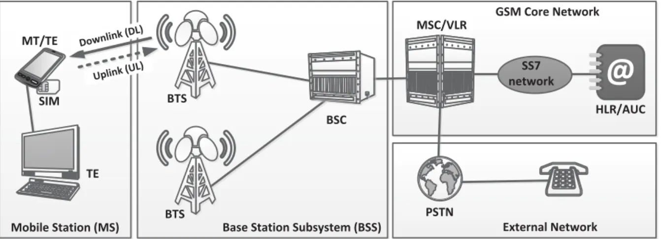
Figure 2.2 shows the general GSM network architecture. The GSM network architecture is divided into four main functional groups, these are:
• Mobile Station (MS): is also known as User Equipment (UE), this entity consists of the terminal equipment and the Subscriber Identity Module (SIM).
• Base Station Subsystem (BSS): this entity handles the radio access func-tions, like radio resource management. It connects the UEs with the core network.
• Core Network (CN): includes the transport functions, mobility management, user/subscriber databases with their information, service controlling func-tions, billing, etc.
• External Network: these are the external networks that the UEs can commu-nicate with and that the mobile network has to be connected to. It can be for example the public telephone network or any other GSM network.
BTS BSC BTS 123 4 56 7 8 9 # 0 * MSC/VLR PSTN GSM Core Network
Base Station Subsystem (BSS) External Network
Mobile Station (MS) MT/TE SIM TE Uplink (UL) Downlink (DL )
@
HLR/AUC SS7 network MT: Mobile Terminal TE: Terminal Equipment BTS: Base Transceiver StationBSC: Base Station Controller MSC: Mobile Switching Center VLR: Visitors Location Registry
HLR: Home Location Registry AUC: Authentication Center
PSTN: Public Switched Telephone Network
Figure 2.2: GSM network Architecture1
One of the important features of a mobile communication system is the radio interface. A radio interface is the interface between the mobile stations and the base station. This interface enables the users of the mobile networks to be mobile with wireless access. The radio spectrum is the term used to describe the amount of resources (i.e., frequency bandwidth/spectrum) that the air interface uses. In mobile communication the radio spectrum is one of the most important parts due to its high incurring cost. In addition, the radio spectrum is often limited and is treated as a scarce resource that the users of the mobile communication system
need to share. The sharing of the spectrum is done using the so-called multiple
access scheme.
In GSM, a mixture of Time Division Multiple Access (TDMA) and Frequency Division Multiple Access (FDMA) is used as the multiple access scheme. FDMA is used to divide the GSM spectrum into several carrier frequencies. Each carrier frequency is then divided using TDMA into 8 time slots that are then used by the mobile stations for their transmissions. The maximum spectrum/frequency band of GSM is 25 MHz, that is 124 carrier frequencies that are separated from each other by 200 kHz. In GSM, Frequency Division Duplex (FDD) is also used to separate the downlink frequency range from the uplink.
GSM uses circuit switched techniques to support voice calls. Due to the emerg-ing needs for higher data rates the General Packet Radio Service (GPRS) has been developed. GPRS is seen as a step along the way from the second generation
mobile communication GSM into the 3rd generation Universal Mobile
Telecom-munication System (UMTS). GPRS offered higher data rates between 56 - 114 kbps compared to the very low rates that can be offered by GSM. This enabled a multitude of possibilities and services to be offered by the mobile operators, for example web browsing. GSM offered for the first time in mobile communication systems the use of packet switching.
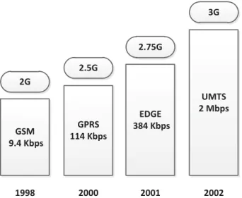
After GPRS, the evolution of the GSM system kept going to support even higher data rates. This lead to the development of Enhanced Data for GSM Evolution (EDGE). The main feature of EDGE was that it enabled data rates up to 384 kbps, which is a significant improvement over GPRS. The increase in the data rate was achieved by changing the GSM modulation scheme from Gaussian Minimum Shift
Keying (GMSK) to 8PSK1. Figure 2.3 shows the evolutions of the GSM system
with their respective data rates.
2G GSM 9.4 Kbps 1998 2.5G GPRS 114 Kbps 2000 2.75G EDGE 384 Kbps 2001 3G UMTS 2 Mbps 2002
Figure 2.3: GSM system evolution
2.2 Universal Mobile Telecommunication System (UMTS)
The first version of the UMTS standards was finalized by the end of 1990, that is why UMTS is also sometimes referred to as release 99 or R99. The main mo-tivation behind UMTS was to define a universal mobile communication standard that aims at higher peak rates, with the ability of dynamically adapting the user data rates. In addition, there were several other targets like the support of Quality of Service differentiation between the different new services offered by UMTS, as well as improving the overall spectral efficiency. UMTS uses Wideband Code Division Multiple Access (WCDMA) which is a completely new multiple access scheme compared to the one used in GSM. It also uses a larger bandwidth of 5 MHz for each of the downlink and uplink.
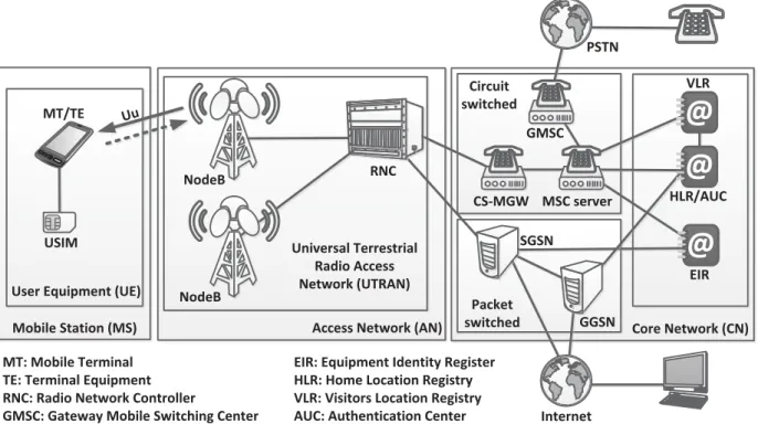
The UMTS architecture (Figure 2.4) is structured similarly to GSM with several modifications. The radio access network in UMTS is called UMTS Terrestrial Ra-dio Access Network (UTRAN), and consists of RaRa-dio Network Controller (RNC) and several NodeBs (which represent the UMTS base stations). The UMTS net-work supports both circuit switched and packet switched connections. The circuit switched connections are used to carry voice services, whereas the packet switched connections are used for other data services, like web browsing through HTTP, and file downloads/uploads through FTP. More details related to UMTS can be found in [HT07].
Similar to GSM, two system enhancements have followed the UMTS system, to increase the data rates, increase the system capacity and reduce system latency. These two enhancements are represented by new 3GPP releases that is release 5 or
NodeB RNC NodeB 123 4 56 7 8 9 # 0 * PSTN Core Network (CN) Access Network (AN)
Mobile Station (MS) MT/TE
USIM
User Equipment (UE)
MT: Mobile Terminal TE: Terminal Equipment RNC: Radio Network Controller
GMSC: Gateway Mobile Switching Center
EIR: Equipment Identity Register HLR: Home Location Registry VLR: Visitors Location Registry AUC: Authentication Center
@
HLR/AUC 123 456 789 #0* 123 456 789 #0* 123 456 789 #0*@
VLR@
EIR CS-MGW MSC server GMSC Circuit switched Internet Packet switched SGSN GGSN Universal Terrestrial Radio Access Network (UTRAN) UuFigure 2.4: UMTS network Architecture1
High Speed Downlink Packet Access (HSDPA), and release 6 High Speed Uplink Packet Access (HSUPA).
HSDPA is already mentioned before the 5th release of the UMTS specification.
The goal of this release was to enhance the downlink data rates of the UMTS standard up to 14 Mbps, increase the spectral efficiency, as well as reduce the system latency. This is achieved by the introduction of several new functions:
• Adaptive Modulation and Coding (AMC): the modulation and coding schemes of each user transmission is adaptively changed depending on the user chan-nel conditions, for example, a user with very good chanchan-nel conditions is assigned a higher modulation and coding scheme.
• Fast NodeB Scheduling: the scheduling function is moved from the RNC to the NodeB compared to GSM. Which means the NodeB can track the instantaneous channel changes of the users and schedule the resources in a more efficient way thus gaining from the multi-user diversity principle.
• Shorter Transmission Time Interval (TTI): the TTI length is reduced in HS-DPA to 2ms, instead of 10ms in UMTS R99. TTI is the duration of a
mission over the radio link, it is also the rate of the radio scheduler at which it takes decisions on which UEs transmit over the next TTI.
• Use of Hybrid Automatic Repeat Request (HARQ): performing retransmis-sions of the erroneous packets between the NodeB and the UE instead of waiting for higher layer retransmissions. This of course will result in la-tency reduction. In addition, chase combining and incremental redundancy are also used to combine the two unsuccessfully decoded packets with the new retransmission to improve the decoding probability.
Similar to HSDPA, HSUPA aims at enhancing the performance of the UMTS R99 uplink in terms of improving the user data rates up to 5.76 Mbps and re-ducing the latency. HSUPA also uses concepts similar to HSDPA: shorter 2ms TTI (optional), HARQ and fast scheduling. However, the AMC is not used in HSUPA since it does not support any high order modulation schemes and it only uses QPSK. This is because higher modulation schemes require more energy per bit resulting in faster battery discharge. In HSUPA, both soft and softer handover are allowed, unlike HSDPA, because the UE is the entity performing the transmis-sion and the neighboring NodeBs can also listen to the UE transmistransmis-sion without any extra effort.
The use of both enhancements (i.e., HSDPA and HSUPA) is often referred to as HSPA. Network operators deploy HSPA in coexistence with R99 UMTS networks. The instantaneous radio performance may vary overtime, sometimes achieving very high cell throughputs. However, the network operators dimension their
back-haul by considering the average performance so as to reduce cost [LZW+08],
which will cause short term congestions in the network backhaul. In order to mit-igate the influence of this, congestion control schemes as well as traffic separation techniques are used to overcome the aforementioned issues and provide QoS
LTE is one of the newest releases of the 3rd Generation Partnership Project (3GPP) specifications. It is also referred to as 3.9G or Release 8. The 3GPP started work-ing on LTE in November 2004 with the Radio Access Network (RAN) Evolution workshop in Toronto - Canada. The main task was to standardize a system with new design goals that can exceed older mobile standards (like UMTS and HSPA), as well as being able to stay competitive at least for the next 10 years.
3.1 Motivation and Targets
In March 2005, a feasibility study on LTE was launched. The main focus of this study was to decide what architecture the new system should have and what multi-ple access techniques were to be used. The LTE network architecture can be seen in Figure 3.1. The main conclusions drawn from the feasibility study [25.05] can be summarized in terms of requirements and targets as follows:
UE eNodeB MME S-GW HSS PDN GW PCRF Uu S1-U S1-MME S6a S11 Gx Rx S5/S8 eNodeB
UE E-UTRAN EPC Services
IP connectivity Layers, The EPS Service connectivity Layer
User plane Control plane SGi Operator’s IP services (e.g. IMS, PSS)
• Simplified flat packet oriented network architecture
• High data rates up to 100 Mbps in the downlink and 50 Mbps in the uplink (even higher with Multi Input Multi Output (MIMO))
• Reduced latency
• Scalable usage of frequency spectrum from 1.25 MHz to 20 MHz
• OFDMA and SC-FDMA as the multiple access techniques for downlink and uplink respectively
3.2 LTE Multiple Access Schemes
In LTE the multiple access transmission scheme is based on the Frequency Domain Multiplexing (FDM). Two different versions are used: Orthogonal Frequency Do-main Multiple Access (OFDMA) for the downlink, and Single Carrier Frequency Domain Multiple Access (SC-FDMA) for the uplink. OFDMA is a very efficient transmission scheme which is widely employed in many digital communication systems, e.g., Digital Video Broadcasting (DVB), WiMax, Wireless Local Area Network (WLAN). The reason behind the popularity of OFDMA comes from the fact that it has very robust characteristics against frequency selective channels. Frequency selectivity is one of the transmission problems that can be overcome through equalization, but the complexity of the equalization technique is very high. Another reason for choosing OFDMA as the downlink transmission scheme is the bandwidth flexibility it offers, since changing the number of sub-carriers used can increase or decrease the used frequency bandwidth.
SC-FDMA is the transmission scheme in the LTE uplink. It provides a low peak-to-average ratio between the transmitted signal; it is a very desirable characteristic for the uplink to have an efficient usage of the power amplifier. This provides a high battery life time for mobile devices.
3.2.1 OFDM
The basic principle of multi-carrier systems is the splitting of the total bandwidth into a large number of smaller and narrower bandwidth units, which are known as sub-channels. Due to the narrow bandwidth sub-channels frequency selectivity does not exist. As a result, only the gains of the sub-channels has to be compen-sated and no complex equalization techniques is required.
In OFDM the sub-channels are orthogonal to each other. This nice property does not require the addition of guard intervals between the sub-channels and hence
it increases the system spectral efficiency. Figure 3.2 shows the orthogonality principle of OFDM; the frequency representation of one OFDM sub-channel is a
Sinc1 function, where if the sampling is done at the exact spacing the result will
only be at the sub-carrier of that sub-channel and zeros at every other sub-carrier frequency. This means that the sub-channels are orthogonal to each other.
Frequency
Time
Sub-Carriers Spectrum (Bandwidth)
Figure 3.2: OFDM signal in frequency and time domain [Hoa05]
3.2.2 OFDMA
Orthogonal Frequency Division Multiple Access (OFDMA) is an access scheme that uses the OFDM principle to orchestrate the distribution of the scarce radio resources among several users enabling multi user communications. This is done by using the Time Domain Multiple Access (TDMA), where users dynamically get some resources at the different time instances of the scheduling.
The LTE MAC Scheduler (explained in chapter 6) makes use of the differ-ent user channel conditions to distribute the frequency resources (sub-carriers) to where it best fits. This can mean giving them to the users, for example with the best instantaneous channel conditions (Max-CI scheduling). This distribution process is determined by the used scheduler discipline.
1The sinc function, sometimes also known as the sampling function, is a function that is widely used
Figure 3.3 shows an example of channel dependent scheduling between two users, where the sub-carriers of the system are distributed between the two users based on who has the best channel. A system with such channel dependent schedul-ing is often very robust with a better system capacity and higher spectral efficiency than a single user OFDM system.
User #2 scheduled Frequency User #1 channel User #1 scheduled Time User #2 channel
Figure 3.3: An example of channel dependent scheduling between two users [ADF+09]
3.2.3 SC-FDMA
As mentioned earlier, the Single Carrier Frequency Division Multiple Access is chosen as the transmission scheme for the LTE uplink. The motivation behind choosing SC-FDMA was the attractive characteristics it possesses, that is having
a low peak to average ratio which is considered to be a very desired property for having efficient power amplifier that can save battery power of the mobile device for the uplink transmission.
SC-FDMA is a special type of OFDM that combines the low peak to average power ratio with multi path resistance and flexible and efficient frequency alloca-tion. It still uses orthogonal sub-carriers similar to OFDMA, but with one differ-ence, that is the sub-carriers used for transmission are chosen to be sequential and not in parallel. A small comparison between SC-FDMA and OFDMA can be seen in Figure 3.4.
15 kHz
Frequency Data symbols occupy
15 kHz for one OFDMA symbol period Time
Frequency Time
SC-FDMA
Data symbols occupy M*15kHz For 1/M SC-FDMA symbol periods
60 kHz CP CP Cons tant subc arrier powe r dur ing ea ch SC -FDM A sym bol per iod 1,1 -1,1 -1,-1 1,-1 Q I
QPSK modulated data symbols
1,1 -1,-1 -1,1 1,-1 -1,-1 1,1 1,-1 -1,1
Sequence of QPSK data symbols to be transmitted
OFDMA symbol OFD MA symbol SC-FDMA symbo l SC-FDMA symbol
Figure 3.4: An example comparing SC-FDMA to OFDMA [Agi09]
3.3 LTE Network Architecture
The LTE system is designed for the packet switched services providing IP con-nectivity between the Packet Data Network (PDN) and the User Equipment (UE) without service interruption even during mobility. The LTE system can be
di-vided into two main branches: Evolved Universal Terrestrial Radio Access Net-work (E-UTRAN) and System Architecture Evolution (SAE). The E-UTRAN evolved from the UMTS radio access network; it is sometimes also referred to as LTE. The SAE supports the evolution of the packet core network, also known as Evolved Packet Core (EPC). The combination of both the E-UTRAN and the SAE compose the Evolved Packet System (EPS). Figure 3.1 shows the general LTE network architecture.
According to [SBT09], an EPS bearer is defined to be an IP packet flow between the PDN-GW and the UE with predefined Quality of Service (QoS) characteristics. Both the EPC and the E-UTRAN are responsible for setting and releasing such a bearer depending on the application QoS requirements. In LTE multiple bearers can be established for users with multiple services, e.g., a user can have a voice call using the Voice over Internet Protocol (VoIP) and at the same time be downloading a file using File Transfer Protocol (FTP), or browse the web using the Hypertext Transfer Protocol (HTTP). Each of these services can be mapped to a different bearer. More detailed explanations on the quality of service and the bearers in LTE are given in section 3.5. In the next subsection a brief description of the important LTE nodes will be presented.
3.3.1 User Equipment (UE)
As the name suggests, a UE is the actual device that the LTE customers use to connect to the LTE network and establish their connectivity. The UE may take several forms; it can be a mobile phone, a tablet, or a data card used by a computer/notebook. Similar to all other 3GPP systems, the UE consists of two main entities: a SIM-card or what is also known as User Service Identity Mod-ule (USIM), and the actual equipment known as Terminal Equipment (TE). The SIM-card carries the necessary information provided by the operator for user iden-tification and authentication procedures. The terminal equipment on the other hand provides the users with the necessary hardware (e.g., processing, storage, operat-ing system) to run their applications and utilize the LTE system services.
3.3.2 Evolved UTRAN (E-UTRAN)
The E-UTRAN in LTE consists of directly interconnected eNodeBs which are connected to each other through the X2 interface and to the core network through the S1 interface. This eliminates one of the biggest drawbacks of the former 3GPP systems (UMTS/HSPA): the need to connect and control the NodeBs through the
Radio Network Controller (RNC), which make the system vulnerable against RNC failures. The LTE E-UTRAN architecture can be seen in Figure 3.5.
MME/ aGW MME/ aGW eNodeB eNodeB eNodeB X2 X2 X2 S1 S1 S1 S1 EPC E-UTRAN
Figure 3.5: LTE E-UTRAN architecture
The enhanced NodeB (eNodeB) entity works as a bridge between the UE and the EPC. It provides the necessary radio protocols to the user equipment, so as to be able to send and receive data and it tunnels the users data securely over the LTE transport to the PDN-GW and vice versa. The GTP tunneling protocol is used, which works on top of the UDP/IP protocols. The eNodeB is also respon-sible for the scheduling which is one of the most important radio functions. The eNodeB schedules the frequency spectrum resources among the different users by exploiting both the time and frequency, while guaranteeing different quality of service for the end users. In addition, the eNodeB also has some mobility man-agement functionalities, e.g., radio link measurements and handover signaling for other eNodeBs.
3.3.3 Evolved Packet Core (EPC)
As shown in Figure 3.1, the EPC (also known as the LTE core network) consists of three main entities: Mobility Management Entity (MME), Serving Gateway (S-GW) and the Packet Data Network Gateway (PDN-GW). In addition, there are some other logical entities like the Home Subscriber Server (HSS) and Policy and Charging Rules Function (PCRF). The main purpose of the EPC is to provide the
necessary functionalities to support the users and establish their bearers [SBT09]. Each of the EPC main entities and their functionalities is described briefly in the next paragraphs. A more detailed description can be found in [36.11a].
The MME entity provides control functions as well as signaling for the EPC. The MME is only involved in the control plane. Some of the MME supported functions include: authentication, security, roaming, default/dedicated bearer es-tablishment, tracking user mobility and handover. The S-GW is the main gateway for the user traffic, where all the users IP traffic goes through. It is the local mobil-ity anchor point for inter-eNodeB handover, as well as the mobilmobil-ity anchoring for inter-3GPP mobility [36.11a]. In addition the S-GW provides several other func-tions like: routing, forwarding, charging/accounting information gathering. The packet data network gateway PDN-GW acts as the user connectivity point for the user traffic, it is responsible for assigning the users IP addresses as well as clas-sifying the user traffic into different QoS classes. In addition, the PDN-GW acts as the mobility anchor point for inter-working with non 3GPP technologies, like Wireless LAN and WiMax.
3.4 E-UTRAN Protocol Architecture
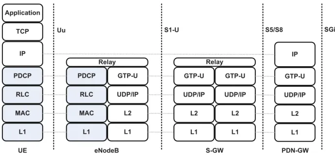
The E-UTRAN protocols consist of both user plane and control plane. The user plane consists of a set of protocols used to transfer the actual user data through the LTE network, whereas the control plane consists of protocols which are used to control and establish the user connections and bearers within the E-UTRAN. Figure 3.6 shows the user plane protocol stack.
L1 MAC RLC PDCP IP TCP Application L1 MAC RLC PDCP L1 L2 UDP/IP GTP-U Relay L1 L2 UDP/IP GTP-U L1 L2 UDP/IP GTP-U Relay L1 L2 UDP/IP GTP-U IP UE eNodeB S-GW PDN-GW Uu S1-U S5/S8 SGi
The LTE radio access architecture is mainly the eNodeB which is an enhanced version of the original NodeB of the UMTS system. Since the RNC was removed from the LTE architecture some of its functions have been moved to the eNodeB. Figure 3.7 shows the detailed eNodeB and UE protocol architecture for the down-link [Dah07]. The main LTE radio interface protocols are [HT09]:
• Radio Resource Control (RRC): is responsible for the handover functions, like handover decisions, transfer of UE context from serving eNodeB to target eNodeB during handover. In addition, it controls the periodicity of the Channel Quality Indicator (CQI) and is also responsible for the setup and maintenance of the radio bearers [Mot].
• Packet Data Convergence Protocol (PDCP): is responsible for compressing the IP header, i.e., reduces the overall overhead which in turn improves the efficiency over the radio interface. This layer also performs additional func-tionalities, e.g., ciphering and integrity protection. A detailed description of the PDCP functionality can be found in [36.11c].
• Radio Link Control (RLC): is responsible for the segmentation and con-catenation of the PDCP packets. It also performs retransmissions and guar-antees in-sequence delivery of the packets to the higher layers. The RLC also performs error corrections using the well-known Automatic Repeat Re-quest (ARQ) methods. A detailed description of the PDCP functionality can be found in [36.10b].
• Medium Access Channel (MAC): is responsible for scheduling air interface resources in both uplink and downlink. It is also responsible for satisfy-ing the users’ QoS over the air interface. In addition, the MAC layer also performs the Hybrid Automatic Repeat Request (HARQ).
• Physical Layer (PHY): is responsible for the radio related issues: e.g., mod-ulation/demodulation, coding/decoding, Multi Input Multi Output (MIMO) techniques.
Header Compression Ciphering PDCP Segmentation, ARQ RLC MAC multiplexing Hybrid ARQ MAC scheduler MAC
Payload selection Priority handling, payload
selection
Retransmission control
Coding
Modulation
PHY
Antenna & resource
mapping
Modulation scheme Antenna & resource
assignment IP packets eNodeB Header Compression Deciphering PDCP Concatenation, ARQ RLC MAC demultiplexing Hybrid ARQ MAC Decoding Demodulation PHY
Antenna & resource
demapping
IP packets
User Equipment (UE)
Redundancy version Transport channel Logical channels R adio bearers SAE bearers
3.4.1 Radio Link Control (RLC)
The radio link control protocol is responsible for the concatenation and segmenta-tion process. It segments the packets that come from the PDCP layer (i.e., the IP packets after compressing the header) into smaller RLC packets, and concatenates the RLC packets on the receiver side into the PDCP packets. In addition to the above functionality, the RLC protocol provides reliable communication between the eNodeB and the UE by the aid of packet retransmissions. The RLC uses se-quence numbers to detect lost packets at the receiver side and inform the sender which packets to retransmit by using some selective repeat retransmissions. This is also known as Automatic Repeat Request (ARQ). The RLC protocol can operate in three different operational modes, these are:
• Acknowledged Mode (AM): which is used to provide error-free transmis-sion between sender and receiver. This mode is suitable for services that use the TCP transport protocol, like FTP and HTTP, where reliability and error free delivery is of the utmost importance.
• Unacknowledged Mode (UM): in this mode no retransmissions are per-formed and RLC only provides segmentation and concatenation function-alities. This mode is suitable for applications that does not require error-free transmission and can tolerate some losses, like VoIP and video conferencing.
• Transparent Mode (TM): this operation mode of RLC does not add any pro-tocol overhead to the higher layer data. It can be used for example for ran-dom access.
The RLC segmentation and concatenation is done based on the MAC scheduler decision, where the scheduler informs the RLC layer on what Transport Block Size (TBS) to be used by a certain user/bearer. This tells the RLC the amount of bits to be sent down to the lower layer. In contrast to the RLC version used in
UMTS/HSPA [ZWL+08] [ZWL+10], in LTE the RLC Packet Data Unit (PDU)
size is not fixed and is dynamically changed based on the scheduler decision. In addition to the retransmission and segmentation/concatenation functionalities of RLC there are a number of other functionalities supported by RLC [HT07]:
• Padding
• In-Sequence delivery of higher layer PDUs
• Duplicate detection
• SN check (unacknowledged data transfer mode)
• Protocol error detection and recovery
• Ciphering
• Suspend/resume function for data transfer
3.4.2 Medium Access Control (MAC)
The MAC layer is responsible for one of the most important functionalities that is scheduling for both downlink and uplink. In addition, the MAC layer provides:
Hybrid Automatic Repeat Request (HARQ), logical channel multiplexing/de-multiplexing, mapping between logical and transport channels, scheduling information
report-ing, priority handling between the UEs, priority handling between the logical chan-nels on one UE, logical channel prioritization and transport format selection.
3.4.2.1 Logical and Transport Channels
As stated earlier, since the MAC layer is located below the RLC layer it provides services to the RLC by offering logical channels. Two different types of logi-cal channels exist, these are traffic and control channels. This classification is done depending on the type of data the channel is transmitting. According to the 3GPP standards [36.11b], the logical channel types defined for the different kinds of services are listed in Table 3.1. The MAC layer uses the services offered by the physical layer in terms of using the Transport Channels. The LTE transport channels are listed in Table 3.2. A detailed description of the LTE logical and transport channels as well as how the mapping between them is done can be found in [Dah07].
![Figure 3.7: Detailed LTE downlink protocol architecture [Dah07]](https://thumb-us.123doks.com/thumbv2/123dok_us/10175699.2919890/50.892.77.763.124.1044/figure-detailed-lte-downlink-protocol-architecture-dah.webp)
![Figure 3.11: SAE bearer model [HT09]](https://thumb-us.123doks.com/thumbv2/123dok_us/10175699.2919890/57.892.208.733.135.442/figure-sae-bearer-model-ht.webp)