Energy Efficiency Oriented Full Duplex Wireless
Communication Systems
Thesis submitted in accordance with the requirements of the University of Liverpool for the degree of Doctor in Philosophy
by
Zhongxiang Wei
Declaration
The work in this thesis is based on research carried out at the University of Liverpool. No part of this thesis has been submitted elsewhere for any other degree or qualification and it is all my own work unless referenced to the contrary in the text.
Abstract
Full-duplex (FD) transmission is a promising technique for fifth generation (5G) wireless communications, enabling significant spectral efficiency (SE) improvement over existing half-duplex (HD) systems. However, FD transmission consumes higher power than HD transmission, especially for millimetre wave band. Therefore, energy efficiency (EE) for FD systems is a critical yet inadequately addressed issue. This thesis addresses the critical EE challenges and demonstrates promising solutions for implementing FD systems, as detailed in the following contributions.
In the first contribution, a comprehensive EE analysis of the FD and HD amplify-and-forward (AF) relay-assisted 60 GHz dual-hop indoor wireless systems is presented. An opportunistic relay mode selection scheme is developed, where FD relay with dif-ferent self-interference (SIC) techniques or HD relay is opportunistically selected. To-gether with transmission power adaptation, EE is maximised with given channel gains. A counter-intuitive finding is shown that, with a relatively loose maximum transmis-sion power constraint, FD relay with two-stage SIC is preferable to both FD relay with one-stage SIC and HD relay, resulting in a higher optimised EE. A full range of power consumption sources are considered to rationalise the analysis. The effects of imperfect SIC at relay, drain efficiency and static circuit power on EE are investigated. Simulation results verify the theoretical analysis.
In the second contribution, EE oriented resource allocation for FD decode-of-forward (DF) relay-assisted 60 GHz multiuser systems is investigated. In contrast to the exist-ing SE oriented designs, the proposed scheme maximises EE for FD relay systems under cross-layer constraints, addressing the typical problems at 60 GHz. A low-complexity EE-orientated resource allocation algorithm is proposed, by which the transmission power allocation, subcarrier allocation and throughput assignment are performed joint-ly across multiple users. Simulation results verify the anajoint-lytical results and confirm that the FD relay systems with the proposed algorithm achieve a higher EE than the FD relay systems with SE oriented approaches, while offering a comparable SE. In addition, a much lower throughput outage probability is guaranteed by the proposed resource allocation algorithm, showing its robustness against channel estimation errors. In the third contribution, it is noticed that in wireless power transfer (WPT)-aided relay systems, the SE of the source-relay link plays a dominant role in the system SE due
to limited transmission power at the WPT-aided relay. A novel asymmetric protocol for WPT-aided FD DF relay systems is proposed in multiuser scenario, where the time slot durations of the two hops are designed to be uneven, to enhance the degree of freedom and hence the system SE. A corresponding dynamic resource allocation algorithm is developed by jointly optimising the time slot durations, subcarriers and transmission power at the source and the relay. Simulation results confirm that, compared to the symmetric aided FD relay (Sym-FR) and the time-switching based WPT-aided FD relay (TS-WPT-FR) systems in the literature, the proposed asymmetric WPT-aided FD relay system achieves up to twice the SE and higher robustness against the relay’s location and the number of users.
In the final contribution, to strike the balance between high SE and low power consumption, a hybrid duplexing strategy is developed for distributed antennas (DAs) systems, where antennas are capable of working in hybrid FD, HD, and sleeping modes. To maximise the system EE with low complexity, activation/deactivation of trans-mit/receive chain is first performed, by a proposed channel-gain-based DA clustering algorithm, which highlights the characteristics of distributed deployment of antennas. Based on the DAs’ configuration, a novel distributed hybrid duplexing (D-HD)-based and EE oriented algorithm is proposed to further optimise the downlink beamformer and the uplink transmission power. To rationalise the system model, self-interference at DAs, co-channel interference from uplink users to downlink users, and multiuser inter-ference in both uplink and downlink are taken into account. Simulation results confirm that the proposed system provides significant EE and SE enhancements over the co-located FD MIMO system, showing the advantages in alleviating high path loss as well as in cutting the carbon footprint. Compared to the sole-FD DA system, the proposed system shows much higher EE with marginal loss in SE. Also, the SIC operation in the proposed system is much more simplified compared to the two benchmarks.
Contents
Declaration i
Abstract ii
Contents viii
List of Figures viii
List of Figures ix
List of Tables xii
Acknowledgement xiii
Nomenclature xiv
1 Introduction 1
1.1 Background and Motivation . . . 1
1.2 Research Contributions . . . 2
1.3 Thesis Organisation . . . 3
1.4 Publication List . . . 4
2 Overview of Wireless Communication Channels and Systems 6 2.1 The Evolution of Wireless Communication Systems . . . 6
2.2 Wireless Communication Channel Models . . . 7
2.2.1 Large-Scale Path Loss . . . 7
2.2.2 Small-Scale Multipath Fading . . . 7
2.3 Orthogonal Frequency Division Multiplexing . . . 9
2.4 Millimetre Wave Communications . . . 10
3 Overview of Full Duplex Systems 13 3.1 Full Duplex Classifications . . . 13
3.1.1 By with or without Relay . . . 13
3.1.3 By Relay Mode . . . 15
3.1.4 By Numbers of Relays or Users . . . 15
3.1.5 By Transmission Directionality . . . 15
3.1.6 Mimicking Full Duplex Systems by Half Duplex Nodes or Or-thogonal Frequencies . . . 15
3.2 Self-Interference Suppression/Cancellation . . . 16
3.2.1 Passive Suppression . . . 16
3.2.2 Analogue Cancellation . . . 17
3.2.3 Digital Cancellation . . . 17
3.3 Power Consumption and Energy Efficiency Challenges in Full Duplex Systems . . . 17
3.3.1 Power Amplify Power Consumption . . . 17
3.3.2 Circuit Power Consumption . . . 18
3.3.3 Additional Power Consumption Incurred by Full Duplex Trans-mission . . . 18
4 Energy Efficiency Comparison between Full Duplex and Half Duplex in Amplify-and-Forward Relay Systems 20 4.1 System Model and Problem Formulation for Full Duplex Amplify-and-Forward Relay Systems . . . 22
4.2 Throughput and Power Consumption Analysis . . . 24
4.2.1 Throughput Analysis . . . 24
4.2.2 Power Consumption Analysis . . . 26
4.3 Transmission Power Adaptation, Energy Efficiency Gain Regions and Opportunistic Relay Mode Selection . . . 27
4.3.1 Transmission Power Adaptation . . . 27
4.3.2 Energy Efficiency Gain Regions and Opportunistic Relay Mode Selection . . . 27
4.4 Parametric Effects on Energy Efficiency Gain Regions . . . 31
4.4.1 Impact of Drain Efficiency on the Energy Efficiency Gain Regions 31 4.4.2 Impact of the Self-Interference Cancellation Amount of Passive Suppression on the Energy Efficiency Gain Regions . . . 31
4.5 Numerical Results . . . 32
4.6 Summary . . . 38
5 Energy Efficiency Oriented Cross-Layer Resource Allocation in Full Duplex Decode-and-Forward Relay Multiuser Systems 39 5.1 System Model and Problem Formulation for Full Duplex Decode-and-Forward Relay Multiuser Systems . . . 42
5.1.2 Problem Formulation . . . 44
5.2 Throughput and Power Consumption Analysis . . . 44
5.3 Energy Efficiency Oriented Cross-Layer Resource Allocation . . . 45
5.3.1 Transformations of the Optimisation Problem . . . 46
5.3.2 Solution to the Cross-Layer Resource Allocation Algorithm . . . 48
5.4 Properties of the Energy Efficiency Oriented Resource Allocation . . . . 49
5.4.1 Impact of Transmission Power on Energy Efficiency . . . 49
5.4.2 Energy Efficiency Oriented Water-Filling for Two-Hop FD Relay Systems . . . 51
5.4.3 Trade-off between Energy Efficiency and Spectral Efficiency for Two-Hop Full Duplex Relay Systems . . . 51
5.4.4 Suitability of the Proposed Algorithm for 60 GHz Applications . 52 5.4.5 Impact of Outage Probability Constraint on Energy Efficiency . 52 5.5 Complexity Analysis . . . 53
5.6 Simulation Results . . . 54
5.7 Summary . . . 60
6 Energy Efficiency Oriented Resource Allocation for Wireless Pow-er TransfPow-er-Aided Full Duplex Decode-and-Forward Relay MultiusPow-er Systems 62 6.1 System Model and Problem Formulation for Wireless Power Transfer-Aided Full Duplex Decode-and-Forward Relay Multiuser Systems . . . . 64
6.1.1 System Model . . . 64
6.1.2 Problem Formulation . . . 67
6.2 Asymmetric Resource Allocation for Wireless Power Transfer-Aided Full Duplex Decode-and-Forward Relay Multiuser Systems . . . 68
6.2.1 Transformation of the Optimisation Problem . . . 68
6.2.2 Solution to the Asymmetric Resource Allocation for Wireless Power Transfer-Aided Full Duplex Decode-and-Forward Relay Multiuser Systems . . . 69
6.3 Complexity Analysis . . . 71
6.4 Properties Discussion for Wireless Power Transfer-Aided Full Duplex Relay Multiuser Systems . . . 71
6.4.1 Relative Length of Time Slots in Wireless Power Transfer-Aided Full Duplex Decode-and-Forward Relay Systems . . . 72
6.4.2 Transmission Power Allocation Policy in Wireless Power Transfer-Aided Full Duplex Decode-and-Forward Relay Systems . . . 73
6.5 Simulation Results . . . 73
6.5.1 Spectral Efficiency Performance . . . 74
6.5.3 Time Duration . . . 77
6.5.4 Convergence Behaviour . . . 78
6.6 Summary . . . 80
7 Energy Efficiency Oriented Resource Management for Bi-Directional Full Duplex Distributed Antenna Systems 81 7.1 System Model and Problem Formulation for Bi-Directional Full Duplex Distributed Antenna Systems . . . 84
7.1.1 System Model . . . 84
7.1.2 Problem Formulation . . . 85
7.2 Throughput and Power Consumption Analysis . . . 86
7.2.1 Downlink Throughput . . . 86
7.2.2 Uplink Throughput . . . 87
7.2.3 Power Consumption . . . 88
7.3 EE Oriented Activation/Deactivation of Distributed Antennas, Down-link Beamformer and UpDown-link Transmission Power . . . 89
7.3.1 Activation/Deactivation of Transmit/Receive Chains at Distribut-ed Antennas . . . 90
7.3.2 Design of Downlink Beamformer at DAs and Uplink Transmission Power at Users . . . 91
7.4 Complexity Analysis . . . 94
7.5 Simulation Results . . . 95
7.6 Summary . . . 99
8 Conclusion and Future Work 101 8.1 Conclusion . . . 101
8.2 Future Work . . . 102
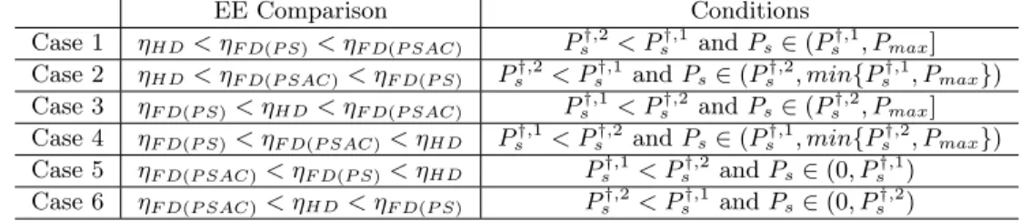
A Proof of Theorem 4.1 104 B Derivative Calculation of EE with respect to the Total Transmission Power 105 C Energy Efficiency Gain Regions among FD(PSAC) FD(PS) and HD 106 C.1 Energy Efficiency Gain Region between FD (PSAC) and FD (PS) . . . 106
C.2 Energy Efficiency Gain Region between FD (PSAC) and HD . . . 106
C.3 Energy Efficiency Gain Region between FD (PS) and HD . . . 107
D Derivation of Lemma 5.2 108
F Theoretic Analysis of the Branch-and-Bound Approach 111
G Proof of Theorem 6.1 114
H Proof of Convergence in Outer Layer 116
I Proof of Rank One 117
J Proof of Convergence in Inner Layer 119
List of Figures
2.1 Waveform of 8 OFDM subcarriers . . . 9
2.2 Simplified block diagram of the OFDM system . . . 11
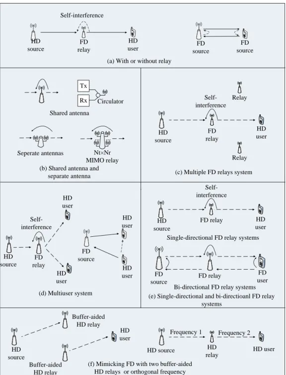
3.1 Classifications of FD systems and their mimics . . . 14
4.1 Block diagram of a simplified FD AF relay-assisted system . . . 22
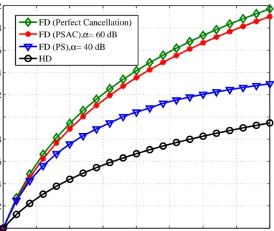
4.2 The average throughputs of the FD (with perfect interference cancel-lation),FD (PSAC, α = 60 dB), FD (PS, α = 40 dB) and HD relay systems . . . 33
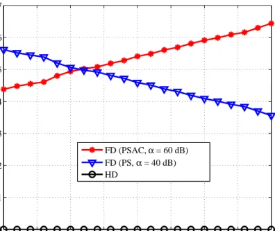
4.3 Average optimal EE performances of FD (PSAC,α = 60 dB), FD (PS, α= 40 dB) and HD relay systems . . . 33
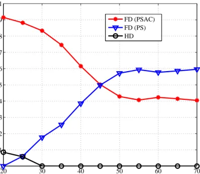
4.4 Probabilities of selecting FD (PSAC,α = 60 dB), FD (PS, α = 40 dB) and HD relay systems . . . 34
4.5 Probabilities of selecting FD (PSAC), FD (PS) and HD, with the amount of self-interference cancelled by AC αAC = 20 dB and the transmission power Ps = 20 mW . . . 35
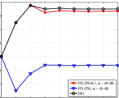
4.6 EE performances of FD (PSAC) and FD (PS), with drain efficiencyω = 25% and 15% . . . 35
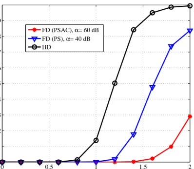
4.7 Outage probabilities of FD (PSAC,α= 60 dB), FD (PS,α= 40 dB) and HD, with total power threshold Pthreshold = 500 mW and transmission power constraint Pmax= 40 mW . . . 36
4.8 Convergence behaviours of the proposed GC algorithm for FD (PSAC, α = 60 dB), FD (PS,α= 40 dB) and HD, with maximum transmission power Pmax = 100 mW . . . 37
5.1 Simplified FD DF relay assisted system in the downlink, with PS, AC and DC of SIC . . . 42
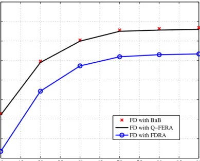
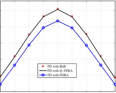
5.2 The average EEs of FD with the BnB approach, FD with the Q-FERA and FD with the FDRA vs. different SIC amounts . . . 54
5.3 The average EEs of FD with the BnB approach, FD with the Q-FERA and FD with the FDRA vs. different normalised distances between S-R, with SIC amountα = 80 dB . . . 55 5.4 The average SEs of FD with the Q-FERA and FD with the FDRA vs.
5.5 The average probabilities that total power consumptions of FD with the Q-FERA and FD with the FDRA exceeds the thresholds Pthreshold =
500 mW and 550 mW, with SIC amountα = 80 dB . . . 56 5.6 The average outage probabilities that the assigned throughput is
high-er than channel capacity, i.e., P r(tk,n > ck,n)∀k ∈ K, n ∈ N, under different channel estimation error, with SIC amountα = 80 dB . . . 55 5.7 The average EEs of FD with the BnB approach, FD with the Q-FERA
and FD with the FDRA vs. different Rician factor ˆk, with SIC amount
α= 60 dB and 80 dB, respectively . . . 58 5.8 The convergence behaviours of the proposed Q-FERA algorithm . . . . 59 5.9 The convergence behaviours of the proposed Q-FERA algorithm with
different transmission power . . . 59 5.10 The average EEs with different outage probability constraints, with
can-cellation amountα = 80 dB . . . 60 6.1 Illustration of asymmetric WPT-aided FD DF relay multiuser system,
where dashed and solid lines denote energy-bearing and information-bearing signals, respectively . . . 65 6.2 Impact of the transmission power at the source on SE performance with
dSR =dRD = 50 m . . . 74
6.3 Impact of the normalised source-relay distance on SE performance with
dSD = 100 m andps = 20 dBm . . . 75
6.4 Impact of the number of users on SE performance with dSD = dRD = 50 m and ps = 20 dBm . . . 76
6.5 Impact of the transmission power on the energy harvested with dSR = dRD = 50 m . . . 76 6.6 Impact of the normalised source-relay distance on the energy harvested
withdSD = 100 m andps = 20 dBm . . . 77 6.7 Impact of the transmission power on the value of (T2−T1)/T withdSR
=dRD = 50 m . . . 78
6.8 Impact of the normalised source-relay distance on the value of (T2−T1)/T withdSD = 100 m andps = 20 dBm . . . 79
6.9 Iteration behaviour on findingµ∗, φ∗, λ∗ . . . 79 7.1 Bidirectional hybrid duplexing DA system, with multiple uplink/downlink
users . . . 84 7.2 Average EE and SE performance vs. different SIC amount, with 16 DAs
and ψ= 0.5×10⁻⁸ . . . 96 7.3 Average required number of reference chains for SIC operation, with
7.4 Average power consumption and EE vs. different number of antennas, withα = 100 dB andψ= 1×10⁻⁹ . . . . 98 7.5 Average power consumption and SE performance vs. different DA
clus-tering threshold values, with α = 100 dB . . . 98 7.6 The number of iterations on finding optimal β∗ by bisection searching,
with left boundβl = 0 and right boundβr = 100 . . . 99
List of Tables
2.1 Requirements and realities of 1G through 4G cellular systems . . . 6 2.2 Types of multipath fading . . . 8 2.3 Statistical parameters in the path loss models of the 60 GHz indoor
channels . . . 12 3.1 Summary of different SIC Schemes for FD systems in terms of EE . . . 19 4.1 Summary of EE gain regions and the corresponding conditions . . . 30 4.2 Simulation setup for FD AF relay systems . . . 32 5.1 Analytical computational complexity (N: number of subcarriers; K:
number of users; δ: required precision factor in iterative search; llte:
number of iteration) . . . 53 7.1 Summary of MIMO FD systems . . . 81 7.2 Simulation setup for hybrid duplexing DA systems . . . 94
Acknowledgement
This thesis would not have been finished without loads of support and help from the following people.
I would like to give my deepest gratitude to my supervisor Dr. Xu Zhu, who has been teaching me with great patient and guiding me from a graduate student to a mature researcher. This work can not be finished without her invaluable comments and constant encouragement. I also appreciate concerns from Prof. Yi Huang for my research. I am grateful to Dr. Sumei Sun at Institute for Infocomm Research, Singapore, where I spent one year as a research assistant and obtained lots of advices and guidance in my research work.
I would like to thank the University of Liverpool, as well as the Department of Electrical Engineering and Electronics, for financing me throughout my Ph.D. period, and providing outstanding training to research students.
I would also like to thank my colleagues: Dr. Yufei Jiang, Dr. Yang Li, Dr. Jun Yin, Dr. Chao Zhang, Ahmed Al-Tahmeesschi, Yanghao Wang, Kainan Zhu, Teng Ma, Yiwei Liu and Boda Liu for creating a family-like atmosphere in the lab. I am pleasure to share my good and tough times with you. Many thanks to Dr. Linhao Dong for your active work on mm-wave communications, which is a corner stone for my research.
Finally, my gratitude is dedicated to my parents, my wife CC and my little angle Yingge. I would had no chance to pursue my dreams in my life without their great support, patience and love. This thesis is dedicated to them.
Haec Otia Studia Fovent
Nomenclature
3D three-dimensional 5G fifth generation AC analogue cancellation
ADC analogue-to-digital converter AF amplify-and-forward
AWGN additive white Gaussian noise BnB branch-and-bound
BS base station cm centimetre
CNR channel-to-noise ratio CoMP coordinated multiple points CP cyclic prefix
CR cognitive radio
CSI channel state information DA distributed antenna
DAC digital-to-analogue converter DAS distributed antenna system DC digital cancellation
DF decode-and-forward EE energy efficiency
E/O electrical/optical converter FD full duplex
FFT fast Fourier transform FW Frank-Wolfe
HD half duplex
ISI inter-symbol interference KKT Karush-Kuhn-Tucker LNA low noise amplifier LO local oscillator LOS line-of-sight LPF low pass filter
LTE long term evolution MAC media access control MIMO multi-input multi-output mm millimetre
MMSE minimum mean square error MRC maximum ratio combining NOMA non-orthogonal-multiple-access
NM nanometre
OFDM orthogonal frequency division multiplexing OFDMA orthogonal frequency division multiple access PA power amplifier
PHY physical layer
PL path loss
PS passive suppression QoS quality-of-service RF radio frequency RMS root mean square RRU radio remote unit
SDP semi-definite programming SE spectral efficiency
SIC self-interference cancellation
SINR signal-to-interference-and-noise ratio SISO single-input single-output
S-V Saleh-Valenzuela TDD time division duplex
TDMA time division multiplex access VCO voltage controlled oscillator VGA variable gain amplifier WPT wireless power transfer ZF zero forcing
Chapter 1
Introduction
1.1
Background and Motivation
Fifth generation (5G) wireless communication systems are calling for significantly in-creased data rate (up to 1000 times higher than current data rate) for much richer multimedia applications, e.g. high definition video and three dimensional (3D) online games [1]. Conventional communication systems operate in half duplex (HD) mode [2], i.e. antennas receive and transmit signal in orthogonal time slots or frequencies. This leads to loss of spectral efficiency (SE). Recently, full duplex (FD) technique has attracted much attention due to its ability to achieve higher SE. FD node can receive and transmit signal simultaneously at the same frequency, which enables significant SE improvement over existing HD systems. However, strong self-interference is introduced at FD node’s receiver from its transmitter and effective self-interference cancellation (SIC) is required at FD node. Thanks to recent advance in SIC, SIC amount of up to 100 dB can be achieved [3], paving the way for the commercial use of FD systems.
On the other hand, to achieve the Gbps-level data rate requirement, using the mil-limetre (mm)-wave band, e.g. frequencies of 28 GHz, 38 GHz and 60 GHz, is a promising solution. With the recent advance of circuit design for mm-wave band [4] [5] [6] [7] [8], there have been growing interests in standardizing its use for 5G communications. Be-sides, the mm level wavelength enables the creation of small-sized antennas and other radio hardware. Some advanced techniques, such as multiple-input multiple-output (MIMO) can be fabricated in the state-of-the-art small-sized terminals. The mm-wave communication systems, however, have inherent disadvantages in that the propagation loss (PL) is high at such high frequency and that the signal can be easily blocked by obstacles due to short signal wavelength (only 5 mm at a frequency of 60 GHz) [9]. To alleviate the high PL and the serious intermittent blockage effect, it is beneficial to employ relay nodes between sources and destinations to assist communications [10]. There have been active research to incorporate FD with mm-wave communications to further improve data rate and reduce latency. A 60 GHz transceiver with FD fibre-optic transmit and receive chains was developed for short-range broadband application
in [11], while FD implementation in mm/sub-mm Si-constructed chips was investigated in [12] [13]. As for the SIC design, it is shown that as much as 80−100 dB of SIC can be achieved at mm-wave frequency by using passive suppression (PS), analogue cancellation (AC) and digital cancellation (DC) [14] [15].
To implement FD and mm-wave in 5G communications, however, high power con-sumption is a critical challenge, because additional power is triggered by SIC at FD nodes [10] and chips working at mm-wave frequency also consume much higher power than that working at a lower frequency. Moreover, the receive and transmit chains of FD node are active at all time, while only one transmit chain or one receive chain of HD node is active at each time slot [16]. To address the high power consumption issue and achieve green communication, energy efficiency (EE) is an important system performance metric proposed in 5G communication systems. However, to the best of our knowledge, there lacks investigation of EE of FD systems. This motivates the work demonstrated in this thesis.
1.2
Research Contributions
The research conducted during this PhD study has produced the following main con-tributions:
• The EE of FD amplify-and-forward (AF) relay systems is investigated, and a comprehensive comparison between FD AF relay and HD AF relay systems is provided. The closed form of EE gain region is given, which clearly reveals the conditions that FD outperforms HD in terms of EE. It is found that with loose transmission power constraint, FD with PS and AC of SIC techniques is even more energy efficient than the FD with PS only and HD relay systems. To improve the system EE, transmission power adaptation and opportunistic relay mode selection are developed. By adopting transmission power adaptation and opportunistic relay mode selection together, both EE and SE of FD AF relay system can be much higher than that of HD AF relay system. To rationalise the system model, a full range of power consumption and imperfect SIC are considered.
• Addressing the practical transmission problems at mm-wave frequency, such as the intermittent signal blockage and out-of-the-date channel information, the cross-layer design for FD decode-and-forward (DF) relay systems is considered in a multiuser scenario. A cross-layer EE oriented algorithm is proposed, by which subcarriers, power at source and relay, and throughput are jointly allo-cated. Compared to the FD DF relay system with a SE oriented algorithm, the proposed cross-layer algorithm achieves much lower outage probability, mak-ing FD DF relay system more robust against to the channel estimation errors.
Besides, a higher EE performance of the proposed EE oriented design is demon-strated over the SE oriented design, at the cost of marginal SE loss. Properties of the EE oriented resource allocation are investigated.
• In wireless power transfer (WPT)-aided FD DF relay systems, the available trans-mission power at relay node is much lower than that at source taking to account the PL from source to relay and low conversion efficiency at relay node. As a result, the end-to-end SE is always bounded by the relay-user hop. To better balance the SE of two hops, a novel asymmetric protocol is developed, which adaptively assigns uneven time slots for the two hops. Based on the asymmetric time slots protocol, a corresponding algorithm is proposed, by joint allocation of transmission power, subcarriers and time slot durations. Besides, we utilise self-interference rather than cancel it. It is demonstrated that more energy can be harvested by the proposed algorithm due to the enhanced of degrees of free-dom. Also, higher SE is achieved compared to the symmetric time slots structure-based algorithm and time-switching-structure-based algorithm.
• FD communications in bi-directional scenario is considered. Different from con-ventional FD MIMO systems, FD is incorporated with DA systems, which has natural advantages in reducing PL and blockage effect. A hybrid duplexing mode is proposed, allowing DAs work in FD, HD or sleeping modes. To maximise the system EE, a channel gain-based DA clustering algorithm is first performed to activate/deactivate transmit/receive chain of DAs, and then beamformer at DAs and transmission power at uplink user are jointly assigned. With the proposed algorithms, the hybrid duplexing FD DA systems feature higher EE, lower power consumption, and simpler SIC circuit design compared to the two benchmarks, conventional co-located FD MIMO system and sole-FD DA system.
1.3
Thesis Organisation
The rest of this thesis is organised as follows. The overview of wireless channels and systems is introduced in Chapter 2. Chapter 3 demonstrates the details of FD systems, including its classifications, SIC design and EE challenges in implementing FD system-s. In Chapter 4, EE comparison between FD and HD in AF relay systems is given, revealing the conditions that FD is greener than its HD counterpart. In Chapter 5, cross-layer design in FD DF relay systems is studied, which addresses the propagation characteristic at 60 GHz. In Chapter 6, WPT-aided FD DF relay system is considered, where the relay is powered by WPT from the source. An asymmetric protocol applica-ble for WPT-aided FD DF relay systems is proposed. In Chapter 7, bi-directional FD DA system is considered, where DAs communicate with multiple users in both uplink and downlink simultaneously. A joint design of the status of DAs, uplink
transmis-sion power and downlink beamformer is presented. Conclutransmis-sions and future work are presented in the final chapter.
1.4
Publication List
A number of publication have arisen during the course of this research, as listed below, all of which have contributed to the thesis.
Journal Papers
1. Z. Wei, X. Zhu, S. Sun, and Y. Huang, “Energy efficiency oriented cross-layer resource allocation for multiuser full-duplex decode-and-forward indoor relay sys-tems at 60 GHz,”IEEE J. Sel. Areas Commun., vol. 34, no. 12, pp. 3366-3379, Dec. 2016.
2. Z. Wei, X. Zhu, S. Sun, Y. Huang, A. Al-Tahmeesschi, and Y. Jiang, “Energy effi-ciency of millimetre-wave full-duplex relaying systems: challenges and solutions,” IEEE Access, vol. 4, pp. 4848-4860, Jul. 2016.
3. Z. Wei, X. Zhu, S. Sun, Y. Huang, L. Dong, and Y. Jiang, “Full-duplex vs. half-duplex amplify-and-forward relaying: which is more energy efficient in 60 GHz dual-hop indoor wireless systems?IEEE J. Sel. Areas Commun., vol. 33, no. 12, pp. 2936-2947, Dec. 2015.
4. Z. Wei, X. Zhu, S. Sun, and Y. Huang, “Energy efficient hybrid duplexing strategy for millimetre-wave bi-directional distributed antenna systems, major revision in IEEE Trans. Veh. Technol.,Sep. 2017.
5. Z. Wei, X. Zhu, S. Sun, and Y. Huang, “Resource allocation in asymmetric full-duplex wireless-powered OFDMA decode-and-forward relay systems,” submitted toIEEE Trans. Wireless Commun., May. 2017.
6. Z. Wei, X. Zhu, S. Sun, Y. Jiang, A. Al-Tahmeesschi, and M. Yue, “Research issues, challenges, and opportunities of wireless power transfer-aided full-duplex relay systems,” submitted to IEEE Access, Sep. 2017.
Conference Papers
1. Z. Wei, S. Sun, X. Zhu, Y. Huang, and J. Wang “Energy efficient hybrid du-plexing and resource allocation for distributed antenna systems,” in Proc. IEEE GLOBECOM’17., Singapore, Dec. 2017.
2. Z. Wei, S. Sun, X. Zhu, and Y. Huang, “Wireless information and power trans-fer: spectral efficiency optimization for asymmetric full-duplex relay systems,” in Proc. IEEE VTC’17 SPR., Sydney, Australia, Jun. 2017. (invited paper)
3. Z. Wei, X. Zhu, S. Sun, Y Huang, and H. Lin, “Cross-layer energy efficiency optimization for multiuser full-duplex decode-and-forward indoor relay networks at 60 GHz,” inProc. IEEE ICC’16., KL, Malaysia, Apr. 2016.
4. Y. Jiang, X. Zhu,E. G. Lin, Y. Huang, Z. Wei, and H. Lin, “Semi-blind precoding aided ML CFO estimation for ICA based MIMO OFDM systems,” inProc. IEEE ICC’16., KL, Malaysia, Apr. 2016.
5. Z. Wei, X. Zhu, S. Sun, Y. Huang, T. Ma, and Y. Jiang, “Energy efficiency optimization for full-duplex relaying with hybrid self-interference cancellation in 60 GHz indoor wireless systems,” in Proc. IEEE/CIC ICCC’15., Shenzhen, China, Nov. 2015. (invited paper)
6. Y. Jiang, X. Zhu, E. G. Lim, Y. Huang, Z. Wei, and H. Lin, “Semi-blind full-duplex relay system with ICA based joint CFO mitigation and equalization,” in Proc. IEEE/CIC ICCC’15., Shenzhen, China, Nov. 2015. (invited paper)
Chapter 2
Overview of Wireless
Communication Channels and
Systems
This chapter outlines the evolution of wireless communication systems. The fundamen-tals of wireless communication channels, orthogonal frequency division multiplexing (OFDM) and mm-wave communications are also presented.
2.1
The Evolution of Wireless Communication Systems
To date, four generations of cellular communication systems have been adopted in the world with each new mobile generation emerging every 10 years or so. First generation analogue cellular systems in 1981; second generation digital technology in 1992, third generation (CDMA 2000, WiMAX) in 2001, and fourth generation (LTE, LTE-A) in 2011, as summarised in Tab. 2.1.
As the demand for data rate in mobile broadband communications increases dramat-ically every year, it is estimated the total mobile traffic will be increased thousand-fold
Table 2.1: Requirements and realities of 1G through 4G cellular systems [17] Generation Requirements Comments
1G No official requirements. Deployed in 1980. Analogue technology.
2G No official requirements. First digital systems. Digital technology. New service such as SMS
and low-rate data. ITU’s IMT-2000 required Primary technologies include 3G 144 kbps mobiles, 2Mbps indoor CDMA2000 1×EV-DO
WiMAX. ITU’s IMT Advanced.
4G Requirements include ability IEEE 802.16m to operate in up to 49 MHz radio LTE-Advanced channels and with high SE ability
by 2020, requiring researchers to seek greater capacity to support richer multimedi-a service beyond the 4G stmultimedi-andmultimedi-ard. As 5G is developed multimedi-and implemented, enhmultimedi-anced system metrics, e.g. higher EE and SE, longer battery life, lower outage probability, lower infrastructure costs, and higher aggregate capacity are expected, by adopting ad-vanced techniques, e.g. FD, mm-wave, massive MIMO, highly directional beamforming antennas.
2.2
Wireless Communication Channel Models
2.2.1 Large-Scale Path Loss
The signal strength reduction caused by large distances between the transmitter and the receiver is referred to as large-scale path loss (PL), which is calculated as
PL =l0+ 10τlog10(d/d0), (2.1) where l0 is the free-space PL at the reference distance and its value varies according to propagation environment and communication frequency. τ is the PL exponent. d
is the distance between two communication nodes. d0 could be set to 1 m in indoor environment or longer in outdoor environment.
2.2.2 Small-Scale Multipath Fading
Multipath fading is the rapid fluctuation of channel gain and change of phases over a short period of time or distance, caused by the constructive or destructive interference of the multiple signal paths between the transmitter and receiver. Multipath fading causes rapid small-scale variation of signals. In urban environments, transmitters and receivers are surrounded by building, trees, moving vehicles and pedestrians, which cause reflection, diffraction and scattering of the transmitted signals. Therefore, the signal undergoes different paths, and each of the paths generates a unique wave of the transmitted signal with the randomly distributed amplitude, phase and delay. The receiver vectorially combines all these waves, and this causes the signal distortion and fading [18] [19]. Letting fi and σi denote the channel gain and delay for the i-th path, respectively, the root-mean-square (RMS) delay spread σ is expressed by
σ= s P ifi2σi2 P ifi2 − P ifi2σi P ifi2 2 . (2.2)
The RMS delay spread interprets the multipath richness. In other words, the higher the RMS delay spread is, the larger the effect of multipath is.
In wireless communications, coherence bandwidth Bc is defined as the range of
Table 2.2: Types of multipath fading
Flat Fading Signal Bandwidth<Coherence Bandwidth Frequency Selective Fading Signal Bandwidth≥Coherence Bandwidth
Fast Fading Coherence Time<Symbol Period Slow Fading Coherence Time≥Symbol Period
correlation. Coherence bandwidth Bc can be derived from the RMS delay spread σ, i.e. Bc≈ 51σ.
On the other hand, the relative motion between the base station and the mobile user causes Doppler shiftfd, which is given by
fd= c
λcosθ, (2.3)
where c represents the velocity of a mobile user moving at. λ is wavelength and θ is the angle between the direction of the received signal wave and the direction of the mobile user’s motion. Doppler spreadBddenotes the difference between Doppler shifts
of signal components. The coherence timeTcis referred to as the time over which two
received signal have a strong potential for amplitude correlation. It can be expressed in terms of the Doppler shiftfm, i.e. andTc= 16πfm9 . Depending on the characteristics
of the transmitted signal, i.e. signal bandwidth and symbol period, and the nature of the multipath channel, i.e. RMS delay spreadσ and Doppler spread Bd, there are
four different fading effects, which are flat fading and frequency selective fading due to multipath delay spread, and fast fading and slow fading due to Doppler spread [20]. These fading effects are summarised in Tab. 2.2.
Assume each symbol is transmitted via signal bandwidth Bs during symbol period Ts. Supposing there areNppaths between the transmitter and the receiver, the channel impulse response (CIR) is given by:
f(t) =
Np−1
X
i=0
fiδ(t−σi), (2.4)
where fi and σi are the channel gain and delay for the i-th path, respectively. The
Rayleigh distribution is commonly used to describe the amplitude |fi|, of which the
probability density function is given by:
p(x) = x
τ2exp(−
x2
2τ2), (2.5)
whereτ2 denotes the time-average power of the received signal. If the received signal contains direct path and a line of sight (LOS) signal is much stronger than the oth-ers, the channel becomes into Rician fading. In Rician fading, the amplitude gain is characterised by a Rician distribution, of which the probability density function is:
S er ia l/P ar al le l Serial /Parallel N p o in t IF F T N point IFFT C P in se rti o n C P insertion P ar al le l/S er ia l Parallel /Seri al S[0] S[1] S[N-1] Ă x[0] x[1] x[N-1]Ă P ar al le l/S er ia l P arall el /S eri al N p o in t F F T N point F FT C P re m o v al CP re m o val S er ia l/P ar al le l S erial/ P arallel Y[0] Y[1] Y[N-1] Ă y[0] y[1] y[N-1]Ă Data steam Data steam
Figure 2.1: Simplified block diagram of the OFDM system.
p(x) = 2(K+ 1)x Ω exp(−K− (K+ 1)x2 Ω )I0(2 r K(K+ 1) Ω x), (2.6) whereK is the ratio between the power in the direct path and the power in the other scattered paths. Ω is the total power from both paths that Ω =v2+ 2τ2, andI0 is the 0-th order modified Bessel function of the first kind.
2.3
Orthogonal Frequency Division Multiplexing
By employing advanced techniques, 5G wireless communication is expected to achieve Gbps-level transmission rate. However, the higher the data rate, the larger the impact of multipath fading. OFDM is one of the effective solutions to handle frequency selective fading, which converts communication over a multipath channel into communication over simpler parallel narrowband subcarriers and has natural advantages in utilizing the wide bandwidth of mm-wave communications. Therefore, OFDM has been selected as one of the key techniques in 5G standards.
The procedure of the OFDM system is presented in Fig. 2.1. Suppose there are
N symbols (S[0], ..., S[N−1]) waiting for transmission. After the inverse fast Fourier transform (IFFT), the transmission data can be presented as:
x[n] =
N−1
X
i=0
S[i]ejN2πin, n∈ {0, ..., N−1}. (2.7)
The received signals are
y[n] =h(n)⊗x[n] +z[n], n∈ {0, ..., N −1}, (2.8) whereh(n) andz[n] are the CIR and noise. The FFT is applied to the received signals after CPR, and recovered signals are
Y[n] = N−1 X i=0 y[i]e−jN2πin, n∈ {0, ..., N−1}, (2.9) which is equal to Y[n] =HnS[n] +Z[n], n∈ {0, ..., N −1}, (2.10)
where Hn and Z[n] are the CIR and noise on the n-th subcarrier in the frequency domain. It can be derived from (2.10) that each transmission data x[n] consists of information fromN symbols, and the information of one symbol has been spread across
N transmission data. Hence, the symbol period in OFDM systems becomes N Ts, leading to a mitigated inter-symbol interference (ISI). In the frequency domain, the frequency range for each symbol is narrowed so that each transmission data carried on one subcarrier undergoes flat fading.
There are several benefits brought by the OFDM technique. First, since the band-width of each subcarrier is narrowed, the system is unlikely to suffer the same fading over all subcarriers in a multipath channel. Hence, there is frequency diversity in OFDM systems. Second, each subcarrier is in flat fading, and therefore the ISI prob-lem in multipath environments is eliminated. Additionally, each subcarrier can be modulated independently in OFDM systems. It leads to a higher SE than conventional single-carrier systems under frequency selective circumstances [18]. Furthermore, as illustrated by Fig. 2.2, OFDM leads to a higher efficiency in spectrum than conven-tional frequency division multiplexing (FDM), where the carriers are not overlapped, and there is a guard band between two adjacent carriers. Of course, there are few disadvantages of OFDM, e.g. the CP occupies an amount of time and transmission power. Also, carrier frequency offset and peak to average power ratio are two practical issues in OFDM systems.
2.4
Millimetre Wave Communications
With the sub-3 GHz spectrum is becoming increasingly crowded and the SE of mi-crowave links has approached its fundamental limits, it is difficult to support the expo-nential growth of mobile data traffic. Since, abundance of communication bandwidth at mm-wave band, 30-300 GHz, remains under utilised [21], mm-wave has been considered as one key technique in 5G communications. To pave the way for commercial use of mm-wave, several standardization activities have been conducted in recent years, e.g. IEEE 802.15.3 Task Group 3c (TG3c) [22], IEEE 802.11ad standardization task group, Wireless HD consortium, wireless gigabit alliance (WiGig), wireless personal area net-works (WPANs) [23] [24] [25] and wireless local area netnet-works (WLANs). Also, there have been active projects, e.g. FP7 EU Project METIS [26], and infield measurements
Frequency
Amplitude
Figure 2.2: Waveform of 8 OFDM subcarriers.
[9] [17] [27]-[31] investigating how mm-wave perform in cellular systems or indoor envi-ronment. Signal propagation at 28 GHz and 38 GHz was measured in urban city, Now York and Austin by [17], proving the communication distance at mm-wave frequency can even achieve hundreds metres in a dense urban environment with highly reflective nature. In [27], 60 GHz band and E band (71-76 and 81-86 GHz) were adopted for backhaul for 5G cellular systems. The statistical parameters of 60 GHz propagation channel in various indoor environments were given by [9] [28] [29], showing the channel follow Rayleigh or Rician distribution depending on the specific communication sce-nario. Beamforming effects on mm-wave channel characteristics were studied by [30]. The channel parameters of narrowband and wideband direction-based beamformers was investigated in [31].
Besides, the design of mm-wave circuitry have been done by [4]-[7]. The authors in [4] designed an integrated 90 nanometre (nm) CMOS 60 GHz transceiver including radio frequency (RF), base band (BB) signal paths, local oscillator (LO) generation and distribution. A 60 GHz wideband power amplifier (PA) fabricated in a standard CMOS 65 nm processors was proposed by [5], and the maximum output saturation power achieves 14.5 dBm with peak power-added efficiency 25% when the PA is supplied by 1.8 V voltage. A 60 GHz 16 quadrature amplitude modulation transceiver including radio frequency (RF) front-end, antenna, analogue, and digital baseband circuitry was
Table 2.3: Statistical parameters in the PL models of the 60 GHz indoor channels [9] Communication scenarios PL in free spacel0 PL exponent
Corridor 1.64
LOS hall 68 dB 2.17
NLOS hall 3.01
designed by [7], which is able to achieve more than 7-Gb/s data rate and has potential to be extended up to 10 Gb/s.
More dedicated research at mm-wave frequency, e.g. OFDM, synchronization, ran-dom access, handover, interference management, and scheduling have been given as well. The media access control (MAC) layer design in mm-wave cellular systems was researched by [32], while multi-hop communication and cooperative diversity perfor-mance were investigated by [33]-[36].
mm-wave communications, however, have inherent disadvantages in high PL and sensitivity to blockage. Since the free space PL increases proportionally as the square of the carrier frequency, the propagation loss at mm-wave band is natural much higher than that at lower frequency bands, e.g. 2 GHz or 5 GHz. Take 60 GHz communication as an example, the PL at reference distance (1 m) is up to 68 dB, as summarised by Tab. 2.3. Also, the signal transmission at mm-wave frequency is easy to be blocked by obstacles due to short signal wavelength (only 5 mm at a frequency of 60 GHz). To alleviate the high PL and the serious intermittent blockage effect, it is beneficial to employ relay nodes between sources and destinations to assist communications. Relay-assisted communication at mm-wave frequency has been investigated by [25] [33] [35]. However, the research in [25] [33] [35] only focused HD transmission, leading to low SE. How to incorporate FD into mm-wave communications is still untouched.
Chapter 3
Overview of Full Duplex Systems
3.1
Full Duplex Classifications
FD systems can be classified in different ways as follows. Especially for FD relay systems, we take a two-hop FD relay system in the downlink as an example, which can be easily extended to a general multi-hop scenario.
3.1.1 By with or without Relay
Without the use of relay, FD systems often refers to the communication between two FD nodes, as shown by Fig. 3.1 (a). The transmission is bi-directional and thus SIC needs to be applied in both two communication nodes. On the other hand, if a FD relay is deployed to help the communication between source and destination, the system can be classified as FD relay system, where the relay can receive and transmit signal simultaneously at the same frequency. Since only relay works in FD mode, SIC is only conducted at relay node. Another more complicated FD relay application is bi-directional FD relay system, which is further clarified in subsection 3.1.5.
3.1.2 By Antenna Type
According to the type of antennas, FD systems can be classified as shared-antenna FD [37] and separate-antenna FD [2], as illustrated by Fig. 3.1 (b).
With shared-antenna, only one antenna set is adopted for both transmission and reception at relay node. A duplexer (circulator) is needed to route the received signal from antenna to the receive chain, and route the transmitted signal to the antenna from the transmit chain.
With separate-antenna, relay can use separate antennas for transmitting and receiv-ing, respectively. In particular, separate-antenna is preferable when MIMO is applied at relay node. This is because the SIC is more complex than that in single-input single-output (SISO) systems, whereas the SIC performance with the shared-antenna configuration is not optimal since the isolation offered by the duplexer may not be sufficient.
HD source FD relay HD user FD source FD relay FD user Self-interference HD source Buffer-aided HD relay HD user HD source FD relay HD user Self-interference Relay Relay HD source FD relay Self-interference HD user HD user Shared antenna Seperate antennas Nt×Nr MIMO relay ... ... Tx Rx Circulator HD source HD relay HD user Frequency 1 Frequency 2
Bi-directional FD relay systems (c) Multiple FD relays system
(d) Multiuser system (b) Shared antenna and
separate antenna
(f) Mimicking FD with two buffer-aided HD relays or orthogonal frequency Buffer-aided
HD relay
Single-directional FD relay systems
(e) Single-directional and bi-directioanl FD relay systems HD source FD relay HD user Self-interference FD source FD source (a) With or without relay
HD user HD user FD source
3.1.3 By Relay Mode
Based on the relay mode, FD relay systems can be divided into AF relay systems and DF relay systems [2] [10].
An AF relay amplifies the received signal from source and forwards it, including the desired signal, noise, and residual self-interference, to destination. Therefore, AF relay systems have simpler circuit design and low power consumption. However, they introduce amplified noise and self-interference to destination.
A DF relay decodes the received signal first, and forwards the re-encoded signal to destination. Hence, the residual self-interference does not affect the link from relay to destination directly. However, a DF relay normally leads to higher power consumption and latency than an AF relay due to its complex signal processing.
3.1.4 By Numbers of Relays or Users
As illustrated by Figs. 3.1 (c) and (d), to combat the high PL and the blockage effect in mm-wave communications, a destination may be assisted by multiple relays [38]. In this case, one can apply relay selection to explore spatial diversity. Also, multiple users may be served by one relay node. In a multiuser scenario, multiple access technique, such as orthogonal frequency division duplexing access (OFDMA), can be adopted [2]. Importantly, the power of self-interference is different across subcarriers. To achieve a better SIC performance, per-subcarrier SIC [3] is desirable.
3.1.5 By Transmission Directionality
According to the transmission directionality, FD systems can be classified into single-directional FD and bi-single-directional FD [39], as illustrated by Fig. 3.1 (e). Single-directional FD systems are involved with an FD relay receiving and transmitting in one direction, while bi-directional FD systems consist of two communication nodes, each operating in FD mode. The two nodes send signals to each other with or without the help of the FD relay node.
3.1.6 Mimicking Full Duplex Systems by Half Duplex Nodes or
Or-thogonal Frequencies
There are some schemes using HD relay to mimic FD relay systems, which is given by Fig. 3.1 (f). One mimicking approach is to use two buffer-aided HD relays to corporate communication between source and destination, where one relay is used to receive the signal from source and the other is used to transmit the buffered signal to destination [40]. However, since two HD relays are needed at the same time, the associated power consumption is high.
Another mimicking approach is to let an HD relay node receive and transmit at different frequencies. However, SE is sacrificed in this case, since the frequency band
is split into two orthogonal parts for transmission and reception individually.
3.2
Self-Interference Suppression/Cancellation
Thanks to the recent advance in SIC techniques [3] [16] [41], the self-interference in FD systems can be mitigated effectively. There are three main approaches to mitigate self-interference: PS, AC and DC [3].
3.2.1 Passive Suppression
The first stage of SIC, PS, mitigates self-interference in the propagation domain, via directional antenna, antenna placement and antenna shielding. Recent research has shown that more than 70 dB of self-cancellation amount can be achieved by PS in an anechoic chamber, and more than 40 dB in a reflected room [42]. The advantage of using PS is that no additional power consumption is required. Fortunately, some features of mm-wave naturally benefit the performance of PS, e.g. the mm level wavelength and the application of directional antenna:
a) As discussed aforementioned, mm level wavelength leads to a much higher PL, which can benefit SIC in the propagation domain. For example, the distance between transmitter and receiver (separate antenna deployment) is 10 centimetre (cm) in a small-sized smart device. The resulting self-interference amount at 60 GHz is 20 dB lower than that at 5 GHz and 28 dB lower than that at 2.4 GHz, respectively, assuming the free space PL exponent [8]. Besides, for the mm level wavelength, a cm level absorptive obstacle between relay’s transmitter and receiver can block the direct path of self-interference effectively.
b) Besides, applying high-gain antennas with narrow beamwidth allows relay to steer beams to concentrate radiated energy in only the desired directions, and the transmitter at relay can point to destination’s receiver. The main lobe of the beam of relay’s transmitter will not be routed into relay’s receiver. As a result, the self-interference comes only from reflected waves, which are much weaker than the direct path. Also, the application of directional antenna is beneficial to the cross-polarization, where transmit and receive antennas in orthogonal polarization states (vertically and horizontally polarised) can achieve a SIC amount of around 20 dB. In summary, PS in mm-wave band can achieve much better performance than that in cm-wave band.
However, PS is sensitive to nearby environment, especially in reflective environment, and PS operation increases the frequency selectivity of the residual self-interference channel. To solve this problem, AC and/or DC can be used to mitigate residual self-interference further, where additional power consumption is required.
3.2.2 Analogue Cancellation
After PS, self-interference can be further mitigated by AC before signal goes through low noise amplifiers (LNAs) [16] [43] [44]. With the ready-made transmit chains and receive chains, there are two kinds of AC designs: direct-conversion architecture AC and non-direct-conversion architecture AC. The former deploys direct-conversion radio architecture to estimate self-interference and subtracts it at relay’s receiver end. This kind of AC circuit design does not need additional baseband signal processing at relay node and thus consumes less power. FD node processes the transmitted signal at trans-mitter to form the predicted self-interference in the analogue-circuit domain. While the non-direct-conversion AC architecture generates the predicted self-interference by pro-cessing the transmit signal in digital domain, adjusts the gain/phase digitally, converts the digital signal to analogue and finally feeds it to the receive chain for AC operation. Since baseband signal processing unit, digital-to-analogue converters (DACs), mixer-s, low pass filters (LPFs), attenuators and adders are required. The incurred power consumption is as high as the equivalent transmit chains.
3.2.3 Digital Cancellation
DC is applied at the last stage, which subtracts the residual self-interference after PS and AC in digital domain [41]. It requires accurate estimation of the residual self-interference following PS and AC. Moreover, the transmitter and receiver distortions need to be captured by DC. Therefore, complex baseband signal processing unit is required by DC operation, which consumes non-negligible power consumption.
The summary of different SIC in FD systems is given by Tab. 3.1.
3.3
Power Consumption and Energy Efficiency Challenges
in Full Duplex Systems
In this section, we discuss the power consumption and the critical EE challenges of FD systems.
3.3.1 Power Amplify Power Consumption
For wireless communication systems, the power consumed by cascaded PAs contributes a large portion to the total power consumption, which is mainly caused by the low drain efficiency. Especially for the chips working at mm-wave frequency, the drain efficiency of current 60 GHz PAs is lower than 25% [5]. This is much lower than the drain efficiency of 2.4/5 GHz PAs, which is normally 30-40% [45] [46]. As a result, chips working in mm-wave band dissipate much more power than the chips working in cm-wave band.
3.3.2 Circuit Power Consumption
Apart from PA power, circuit power also contributes a large part to the total power consumption. Generally, circuit power is the the power consumed by the signal process-ing parts, includprocess-ing LNAs, filters, DAC, analogue-to-digital converter (ADC), voltage controlled oscillator (VCO), dividers, local oscillator (LO) buffer, decoder, compara-tors, variable gain amplifier (VGA) etc [4]. It is worth mentioning that, limited by the start-of-the-art hardware design, circuit power consumed by a mm-wave chip is also higher than that consumed by a cm-wave chip [4].
3.3.3 Additional Power Consumption Incurred by Full Duplex
Trans-mission
HD transmission splits the transmission into two orthogonal time slots, and only one receive chain or one transmit chain is active at each time slot. While in FD systems, both transmit chain and receive chain are active at all time. Therefore, the power consumption of FD systems is naturally higher than that of HD systems.
The other additional power consumption of FD node is incurred by SIC. Generally speaking, complex SIC scheme needs more involved components and consumes higher power. For example, the AC operation design in [3] needs DAC, transmit radio unit and adder to mitigate self-interference. The additional power consumption incurred by the SIC is even comparable with the power consumption of the equivalent transmit chains [41]. Another kind of AC design in [16] uses tunable attenuation and delay unit to route the estimated signal to the receiver for SIC. Attenuator, delay units and adders are required to adjust the delay and the amplitude, and the introduced power consumption is still non-negligible.
Besides, the power consumed by DC operation is also non-negligible. Since DC design needs to calculate the equivalent baseband signal after PS and AC operations, where digital baseband signal processing unit is required [3].
Table 3.1: Summary of different SIC schemes for FD systems in terms of EE SIC schemes Approaches Additional power con-sumption Features Drawbacks Benefiting from high
PL between relay’s transmitter and re-ceiver
Nil Much higher PL than the PL with cm wave
Sensitive to envi-ronment; Increased frequency selectivity of self-interference channel
PS Antenna shielding Nil Fully exploiting the advantage of mm lev-el wavlev-elength Sensitive to envi-ronment; Increased frequency selectivity of self-interference channel
Directional antenna Nil Widely used in mm-wave commu-nications; Relay’s transmitter point-ing to destination with no direct self-interference Sensitive to envi-ronment; Increased frequency selectivity of self-interference channel Direct-conversion ar-chitecture
Low Aware to the reflect-ed self-interference Sensitive to wide-band self-interference AC Non-Direct-conversion archi-tecture
High Unaware to the reflected self-interference
Not feasible in AF re-lay systems
DC Digital-domain can-celler
High Inefficient given good performance by P-S+AC, may degrade the EE performance
May cause negative effect to system (the introduced noise power is higher than the power of the self-interference cancelled)
Chapter 4
Energy Efficiency Comparison
between Full Duplex and Half
Duplex in Amplify-and-Forward
Relay Systems
Nowadays, wireless communications are required to support much richer multimedia applications, such as uncompressed high definition TV and high speed video download-s. The 60 GHz frequency band, with an extremely large bandwidth of up to 7 GHz, is a promising candidate for high speed indoor wireless networks [25]. However, the 60 GHz transmission requires line-of-sight (LOS) and suffers significant propagation loss due to inherent disadvantages at such high frequency [17]. Also, it is challenging to maintain robust network connectivity at 60 GHz networks. As the wavelength at 60 GHz is only 5 mm, links are easily blocked by obstacles, such as human body and furniture. Applying relay is a leverage to extend network coverage while maintaining robust connectivity [33]. Conventional relays work in HD mode, while FD relay sys-tem [2], which allows transmitting and receiving at the same frequency and the same time, enables a significant enhancement of system throughput and has attracted much attention. Whereas, it suffers loop interference and requires effective self-interference mitigation [42].
On the other hand, 60 GHz chips generally consume much more power than the chips working at a much lower frequency [4]. Therefore, there is an urgent demand for maintaining high throughput while limiting energy consumption [47], which has attracted much attention from vendors and researchers, e.g. the IJOIN project [1]. EE, defined as the ratio of system throughput to total power consumption [47], is an important measure of green communication solutions. The EE of the relay-assisted indoor wireless network at 60 GHz should be investigated. It is also interesting to compare the EE achieved by FD relay systems with its HD counterpart.
[48], or finding the rate gain region (the rate gain region is defined as the region where one relay mode outperforms another mode in terms of throughput) with specific self-interference mitigation technique [49]. The EEs of FD and HD relay systems have not been investigated. A power consumption model was presented in [50] for HD relay-assisted 60 GHz systems. It did not consider FD mode nor static circuit power, which is actually comparable with the transmission power in indoor environments. The total power consumption mainly includes two parts in indoor environment: PA power and circuit power. The circuit power consumption modelled in [51] is oversimplified and inaccurate due to lack of power consumption details. The circuit power modelled in [52] contains various power consumption sources including DAC, mixer, LNA, ADC, etc. However, the circuit power was assumed to be fixed, neglecting the fact that part of the circuit power is dependent on the throughput state. On the other hand, R. Bolla et al. [47] explored various perspectives of power consumption and energy saving operations, such as dynamic adaptation and sleeping/standby. In [53] and [54], the EE of direct transmission (without relay) was investigated. In [53], the EE was investigated for OFDMA networks. Li et al. [54] presented multiple transmission schemes to minimise energy consumption for wireless video transmission. [55] and [56] presented the analysis of the EE of HD relay systems. [55] showed how HD relays should be positioned to outperform direct transmission in terms of EE. In [56], a multipath routing algorithm was presented for an HD relay system, where only the transmission power is included into the power consumption model. There lacks an analysis of the EE of FD relay systems in the literature.
In this chapter, we provide a comprehensive EE analysis for a dual-hop FD AF relay-assisted OFDM system, which is one of the most important application scenario for FD wireless communication systems. Our work is different in the following aspects.
• To the best of our knowledge, this is the first work to investigate the EE of the FD relay systems and to compare it with its HD relay counterpart. It is shown that with given transmission power at the source, the FD relay systems can be more energy efficient than the HD relay systems.
• The EE gain regions between FD (PSAC), FD (PS) and HD, where one relay mode outperforms another mode in terms of EE, are clearly defined. It is shown that FD with two-stage SIC (PSAC) can be even more energy efficient than FD with one-stage interference cancellation (PS only) as well as HD, if the transmission power is relatively high and satisfies certain conditions. This enables opportunistic relay mode selection among FD (PSAC), FD (PS) and HD to optimise the EE under a maximum transmission power constraint. A low complexity algorithm is proposed to optimise the EE.
TX RX TX RX PA LNA LNA Source Relay Destination Self-Interference Passive Suppression Analog Cancellation PA
Figure 4.1: Block diagram of a simplified FD AF relay-assisted system.
model and their effects on EE are discussed. In particular, the powers consumed by the relay node and SIC are considered, which were absent from the previous work on power consumption modelling. The impact of imperfect SIC is also considered in our analysis.
4.1
System Model and Problem Formulation for Full
Du-plex Amplify-and-Forward Relay Systems
Assume a 3-node dual-hop AF relay system. AF relay mode is employed because it requires relatively simple signal processing and low operational power [57]. The block diagram of the FD AF relay-assisted system is illustrated in Fig. 4.1, where PAs are employed at the transmitters of the source and the relay, while cascaded LNAs are placed at the receivers of relay and the destination. It is assumed that the destination cannot hear the source directly due to high attenuation at 60 GHz [25] [33], and the relay is positioned in the middle of the source-destination link to maintain a high throughput [58]. The relay in FD mode transmits and receives at the same time and frequency, causing self-interference to the receiver from its transmitter. To reduce the self-interference, PS and AC are applied, as shown in Fig. 4.1. DC is not considered in this model due to high complexity and performance limitations (PS and AC only can be sufficiently effective for AF FD relay systems [59]). Let α denote the total amount of SIC on each subcarrier, which is defined as the ratio of the self-interference powers before and after suppression/cancellation. PS includes directional antenna and antenna shielding. An absorptive shielding (or absorber) between the relay’s transmit antenna and receive antenna can block self-interference by around 10 dB in addition to directional antenna [42]. LetαP Sdenote the total amount of self-interference cancelled by PS. The AC circuit design in [16] is adopted due to its simple implementation and no requirement for baseband signal at relay node. Its SIC amount is denoted byαAC.
allocated power are different across subcarriers. Ideally, the self-interference mitigation should be operated subcarrier by subcarrier. However, it is impossible for PS and also imposes extremely high complexity for AC. Therefore, for both PS and AC, SIC is frequency-flat cancellation practically: the SIC amountαis identical across all subcar-riers. Thus, α=αP S in FD (PS) and α=αP S+αAC in FD (PSAC). In general, αP S
= 40 dB or more can be achieved by PS alone, and αAC = 20∼40 dB [43] [16].
OFDM transmission is assumed withN subcarriers. LethSR,n,hRD,nandhRR,n de-note the channel frequency responses of links source-to-relay (S-R), relay-to-destination (R-D) and relay-to-relay (R-R) on subcarriern, respectively. Also letlSR,lRD andlRR
denote the PLs of links S-R, R-D and R-R, respectively. The channels of the S-R and R-D links are modelled as Rician fading. It is widely used for 60 GHz channel modelling [36] [29], especially with directional antenna and beamforming, which are essential for 60 GHz frequency band to combat high PL. The Saleh-Valenzuela (S-V) model is sim-ilar to the Rician model if the direct link is not blocked and its strength is relatively high compared to other non-direct components [8]. The self-interference channel is modelled as Rayleigh fading as the LOS between the transmitter and the receiver of the relay can be easily blocked by antenna shielding due to very small wavelength at 60 GHz. Applying narrow beamwidth antenna also reduces the LOS signal strength between relay’s transmitter and receiver due to the main lobe of the relay’s directional transmit antenna pointing to the destination. The self-interference waves are collected from the reflected waves [8].
Assume that the PAs have equal power gain ofβ, and the LNAs have the same gain
Gand noise figureF each [50]. Letsn[k] denote the transmitted signal at the source on
subcarriernin time slotk, andPs,n is the allocated transmission power at the source.
Similarly, definetn[k] as the transmitted signal at the relay on subcarriernin time slot
k. zR,n[k] andzD,n[k] denote complex additive white Gaussian noise (AWGN) elements
on subcarrier n introduced at the relay and destination, respectively, with zero mean and varianceσ2.
With residual self-interference, the received signal at the relay node on subcarrier
nin time slotk is expressed as:
rn[k] =hSR,n p lSRPs,nsn[k] +hRR,n r 1 αtn[k−τ] +zR,n[k], (4.1)
where τ (≥ 1) is the integer symbol processing delay, which is typically long enough to guarantee that the symbol transmitted at the relay is uncorrelated with the symbol received simultaneously [60]. The signal received at the relay passes through cascaded LNAs and PA. Thus, the transmitted signaltn[k] from the relay is given by
tn[k] = p βGhSR,n p lSRPs,nsn[k] +hRR,n r 1 αtn[k−τ] + √ F zR,n[k] . (4.2)
as yn[k] =hRD,n p βG2l RD hSR,n p lSRPs,nsn[k] +hRR,n r 1 αtn[k−τ] + √ F2z R,n[k] + √ GF zD,n[k]. (4.3)
EE (bits/Joule) is calculated as the ratio of the system throughput to the total power consumption. In conventional cellular networks, circuit power dominates the power consumption and the consumed transmission power is negligible. As illustrated in [61], the circuit power of base station is dominant and could be up to 3700 W in a macro-cellular network. Thus, its EE can be approximated by η = Pc,sta+εTT
+ξPAC.
Higher EE is pursued by setting the transmission power as high as possible to achieve a high throughput. In 60 GHz indoor systems, however, higher throughput may lead to lower EE due to enhanced transmission power, which cannot be neglected in total power consumption.
Our objective is to optimise the instantaneous EE η, i.e.
argmax Ps T P s.t Ps≤Pmax. (4.4)
Now we discuss how to optimise EE by transmission power adaptation at source under a maximum transmission power constraint. Then the EE gain regions between FD (PSAC), FD (PS) and HD relay modes are researched. With opportunistic relay mode selection and transmission power adaptation, EE is maximised. Some parametric effects on EE gain regions are discussed as well.
4.2
Throughput and Power Consumption Analysis
4.2.1 Throughput Analysis
The received signal at the destination is rewritten as
yn[k] =hRD,n p βG2l RDhSR,n p lSRPs,nsn[k] | {z } desired signal +hRD,n p βG2l RDhRR,n r 1 αtn[k−τ] | {z } self-interference +hRD,npβG2lRD√F2zR,n[k] +√GF zD,n[k] | {z } equivalent noise , (4.5)
where the equivalent noise consists of the noise introduced at the relay and destination. Let Γn denote the signal-to-interference-and-noise ratio (SINR) on subcarriern at the
g3,n = β2G3F3|hRD,n|2lRD|hRR,n|2 and g4,n = β2G3|hSR,n|2lSR|hRD,n|2lRD|hRR,n|2.
According to (4.5), the SINR on subcarrier nat the destination with FD relay can be derived as
ΓF D,n =
g1,nPs,n g2,nσ2+PI,n/α
, (4.6)
where PI,n = g3,nσ2 +g4,nPs,n represents the power of the self-interference, g2,nσ2 is
the power of the equivalent noise andg1,nPs,nis the power of the desired signal. Unlike [49] which assumed a bidirectional P-to-P FD system, in our system model, the noise introduced at the relay node and the residual self-interference after cancellation are forwarded to the destination, which can be observed from (4.5) and (4.6). The overall throughput of FD is given by TF D = N X n=1 W N log2(1 + ΓF D,n), (4.7)
whereW denotes the total bandwidth whileN denotes number of subcarriers. For HD relay transmission, the SINR ΓHD,nis calculated by setting the self-interference related
elements in (4.6) to 0 and 1/2 is added before the log function in (4.7).
To outperform HD in terms of throughput on subcarrier n, the following equation should be satisfied by FD:
W
N log2(1 + ΓF D,n)> W
2N log2(1 + ΓHD,n). (4.8)
Substituting (4.6) into (4.8) yields
α > g3,nps,n+g4,nσ
2
p
(g1,nps,n+g2,nσ2)(g2,nσ2)
. (4.9)
Equation (4.9) indicates that the required SIC amount making FD outperform HD in terms of throughput on subcarriern. It is obvious that a higher cancellation amount can satisfy (4.9) more easily. To increase the SIC amount, many cancellation schemes have been proposed [3] [16] [42] [43] [44]. With proper SIC design, the power of self-interference can be lower or even negligible compared to noise power. As shown from (4.9), higher power gain β at amplifier requires more SIC amount α at relay node. It is because improving power gain can improve the SINR at the second hop R-D, but corrupt the SINR at the first hop S-R. The effect of amplifier power gain β on the first hop is much more significant than its effect on the second hop because the distance between relay’s transmitter and receiver is much shorter than the distance between relay’s transmitter and destination’s receiver. Therefore, higher SIC amount
α is required for a higher value of β. Also, LNAs at relay are placed at the front-end of relay’s receiver. Normally, the effect of noise from subsequent stages (e.g. noise introduced at the destination) is reduced by the gain of the relay’s LNAs in a dual-hop network. Therefore, high gain LNA is preferred at the relay (the noise figure is