Autonomous High-Speed Overtaking
in Structured Environments
Shilp Dixit
Supervisors: Dr. Saber Fallah
Dr. Umberto Montanaro
Examiners: Prof. Mark Cannon
Prof. John F Watts
Mechanical Engineering Sciences
University of Surrey
This dissertation is submitted for the degree of
Doctor of Philosophy
Faculty of Engineering and
To my grandparents
śrīmatī Mahālakṣmī Dīkṣita& śrī Harivallabha Dīkṣita śrīmatī Sulocanā Dvivedī& Dr. Prāṇaśaṃkara Dvivedī
and my parents
समानी व आकूित: समाना हदयािन व: । समानमतु वो मनो यथा व: सुसहासित ॥८:४९:४॥
–ऋग्वेद
United be your purpose, harmonious be your feelings, collected be your mind, in the same way as all the various aspects of the universe exist in togetherness, wholeness..
Declaration
I hereby declare that except where specific reference is made to the work of others, the contents of this dissertation are original and have not been submitted in whole or in part for consideration for any other degree or qualification in this, or any other university. This dissertation is my own work and contains nothing which is the outcome of work done in collaboration with others, except as specified in the text and Acknowledgements.
Shilp Dixit December 2019
Acknowledgements
My journey through this PhD has been a truly life-changing experience which would not have been possible without the guidance, help, and support that I received from many people.
First and foremost I wish to say a very big thank you to my supervisor Dr. Saber Fallah who gave me an opportunity to work on this exciting project and become a part of his research lab. We have spent many hours discussing the various technical aspects of the work, applying polishing touches to the papers, and finalising the project deliverables in his office and I am truly grateful that he gave me freedom to explore the different facets of the thesis while being supportive. He has also encouraged me to grow professionally by letting me explore other opportunities via research assistantships and external projects.
A very special thank you to my co-supervisor Dr. Umberto Montanaro for his support and guiding me through the various phases of the PhD. His passion for mathematics and control engineering is contagious and I am thankful of all his help with writing mathematical proofs and technical papers. I sincerely thank him for his mentorship that helped me improve my ability for formulate mathematical problems and showed me the way to become a more rounded researcher. I fondly look back at the many riveting discussions we had over the years on topics beyond control engineering which presented me with a different perspective and played a key role in my development as an individual. Without his guidance and constant feedback this PhD would not have been achievable.
I gratefully acknowledge Jaguar Land Rover and the entire CARMA team for the financial support and in making the project come to life. As the PI of the CARMA team, Professor Mehrdad Dianati’s valuable feedback and encouragement to extract the best output from our work helped immensely in pushing us to become the best possible researcher and I am thankful to him for imbibing this quality within the group. Thank you to David Oxtoby and Tom Mizutani from JLR for all their support with the knowledge transfer and publications throught the duration of the PhD. I am also grateful to Mete Türedi and Maxime Penet for their tremendous help with moving towards the implementation of the steering controller on a test vehicle. Their
on the experimental vehicle.
I would also like to thank the members of my defense committee, Professor John Watts and Professor Mark Cannon for their time and insightful questions.
A pleasant and fun atmosphere in the working group is important for surviving a PhD program and I feel lucky that I got the opportunity to share the lab with a fantastic group of passionate researchers. From collaborating and sharing each other’s research via monthly meetings to burger & beer outings, each resulting in a memorable event and a valuable lesson that I will remember and cherish for a long time. I shared my penchant for sporting activities with my friends in the lab; the tennis tutorials with Mathias Metzler and Alessandro Scamarcio, squash sessions with Joao Aguiar and Shayan Taherian were some of my favourite activities outside research that I really looked forward to throughout my years at Surrey. The PhD program is fraught with peaks and troughs and but my labmates were always there to help and I feel grateful of the support and assistance that everyone in the lab extended to their fellow colleagues. A special mention to Arvind Tiwari, Piyush Mohanty, Kaushik Halder, and Ashish Sharma for sharing their delicacies with me and making me look forward to stealing their food.
I was also involved in activities outside university and I was lucky to get an opportunity to play Sunday English cricket with an amazing set of team-mates at the Uplands Cricket Club. The weekends spent playing cricket all over the Surrey countryside were among the highlights of my time as a PhD researcher. I am thankful to all of them for the many enjoyable matches and subsequent discussions reminiscing our exploits on the field and I hope I get to play with them next summer. A big thank you to all my friends from school and previous universities. Most of them are spread all over the globe but were there to support me at all times and I am really thankful for their friendship over the years.
A special shoutout of appreciation and gratitude to my friend Aswin Vairamani, my cousin Rohinee Didi, and my aunt Sudha Bua for their invaluable help in refining the thematic and philosophical aspects of the thesis.
Lastly, I thank my family for all their love, patience, and encouragement. My parents have always supported me in all my pursuits and raised me to be curious about science and technology. My elder brother Ishan, my Anisha Bhabhi, and younger brother Avi have always motivated me to follow all my dreams and I am lucky to have their constant guidance and support. A huge thank you to Sitara for being such a perfect baby and lighting up my phone screen with her antics during all video calls. Thank you.
Abstract
In this thesis, we design and develop controllers for trajectory planning and trajec-tory tracking to tackle autonomous high-speed overtaking for the next generation of autonomous vehicles. Both the controllers are developed for a JLR Range Rover Sport that is capable of autonomous driving functionalities. To assist with con-troller development, a high-fidelity vehicle model previously developed in IPG Carmaker is utilised that contains all the multi-body interactions and non-linear tyre characteristics.
Trajectory Planning
Autonomous high-speed driving is a safety-critical task and it is imperative that the planned trajectory of the vehicle can ensure safety (collision-avoidance) while computing smooth and feasible trajectories. We propose a trajectory planning frame-work that utilises information of the traffic vehicles to identify safe driving zones on the road using potential field functions and a robust model predictive controller for generating feasible trajectories that ensure the vehicle remains within the safe zones while performing the overtaking manoeuvre. The closed-loop performance of this controller is validated in a high-fidelity co-simulation environment.
Trajectory Tracking
The trajectory tracking controller is designed to ensure that the vehicle tracks the trajectory as closely as possible and preserves the lateral-yaw stability at all times. In this thesis, an Enhanced Model Reference Adaptive Control algorithm is used to design a generic lateral tracking controller for an autonomous vehicle. The control algorithm is applied to a vehicle path tracking problem and its tracking performance is investigated when subjected to external disturbances such as crosswind, road surface changes, modelling errors, and parameter miss-matches in a high-fidelity co-simulation environment.
Finally, the design of a combined motion planning & control scheme is carried out. The lateral tracking controller is augmented to include the dynamics of the steering actuator system and the updated tracking controller is combined with the RMPC based sophisticated path-planning framework to present a hierarchical closed-loop control architecture for autonomous overtaking. This architecture is implemented on the IPG CarMaker/Simulink environment and validated with different overtaking manoeuvring scenarios.
Table of contents
List of figures xvii
List of tables xxi
Nomenclature xxiii
1 Introduction 1
1.1 Motivation . . . 1
1.2 Objectives . . . 3
1.3 Outline&Contributions . . . 4
2 Background&Literature Review 7 2.1 Introduction . . . 8 2.2 System Architecture . . . 12 2.3 Trajectory Planning . . . 13 2.4 Trajectory Tracking . . . 19 2.4.1 Tracking Controllers . . . 21 2.5 Summary . . . 25 3 Trajectory Planning 27 3.1 Introduction . . . 27
3.2 Mathematical Notations and Definitions . . . 31
3.3 Control Oriented Vehicle Model . . . 32
3.4 Control Formulation . . . 35
3.4.1 MPC with Terminal Set Constraints . . . 35
3.4.2 Robust MPC with Terminal Set Constraints . . . 37
3.5 Local Risk Map . . . 40
3.5.2 Road Potential . . . 41
3.5.3 Lane Potential . . . 42
3.5.4 Car Potential . . . 42
3.6 Selection of the Target Point . . . 43
3.7 Trajectory Generation . . . 45
3.7.1 Nominal MPC . . . 45
3.7.2 Robust MPC . . . 46
3.7.3 Collision Avoidance Constraints . . . 47
3.8 Numerical Results . . . 50
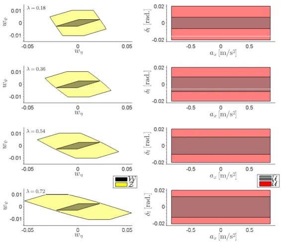
3.8.1 Robust positive invariant set and MPC implementation . . . . 53
3.8.2 Simulation Results . . . 54
3.9 Summary . . . 60
4 Trajectory Tracking 63 4.1 Introduction . . . 63
4.2 Mathematical Notations and Definitions . . . 67
4.3 Control Formulation . . . 70
4.4 Path Tracking . . . 76
4.5 Numerical Validation . . . 80
4.5.1 Manoeuvre I: Navigating a hypothetical highway section . . . 81
4.5.2 Manoeuvre II: Driving in crosswind . . . 86
4.5.3 Manoeuvre III: Lane change in low friction conditions with additional passengers . . . 87
4.6 Summary . . . 93
5 Combined Motion Planning&Control 95 5.1 Introduction . . . 95
5.2 Steering Actuator Dynamics . . . 100
5.2.1 Model Augmentation . . . 101
5.3 Control Law . . . 103
5.4 Test Track . . . 103
5.4.1 Local Reference Curvature Generation . . . 104
5.4.2 Numerical Validation . . . 106
5.5 High-Speed Overtaking . . . 113
5.5.1 Local Reference Trajectory . . . 114
5.5.2 Numerical Validation . . . 115
Table of contents
6 Conclusions&Recommendations 127
6.1 Conclusions . . . 127
6.2 Recommendations . . . 131
6.3 Closing Remarks . . . 132
References 135
Appendix A List of Parameters for Initialisation 151
Appendix B Development of a Prediction Model 155
Appendix C Derivation of Cost Function: Nominal MPC 159
Appendix D Derivation of Cost Function: Robust MPC 161
Appendix E Frequency Response: Vehicle Lateral-Yaw Dynamics 163
Appendix F Determination of Look-Ahead Distance 165
F.1 Medium-speed driving . . . 166
F.2 High-speed driving . . . 167
Appendix G Design of Controllers for Reference Model 169
G.1 Design of Reference Feedforward Controller: K∗R . . . 169
G.2 Design of Reference Feedback Controller: KX∗ . . . 170
List of figures
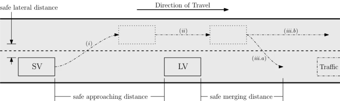
2.1 Basic schematic of an overtaking manoeuvre. Note: Different sub-manoeuvres are (i) lane-change; (ii) pass lead vehicle; (iii.a) merge back into original lane; (iii.b) continue in faster lane to pass traffic . . 10
2.2 Visibility of an autonomous vehicle. Note: SV: Subject Vehicle, TV: Traffic Vehicle. Sensor performance specifications are based on [39] . 11
2.3 Overview of an autonomous driving system . . . 13
2.4 General control architecture for an autonomous vehicle [43,48,54–56]. (V2X block with dot-dash boundary: optional functionality) . . . 14
2.5 Trajectory planning via (a) Potential Fields [48]; (b) RRT [68]; (c) Vir-tual Reference Tracking [10]; (d) Model Predictive Control [52] . . . . 17
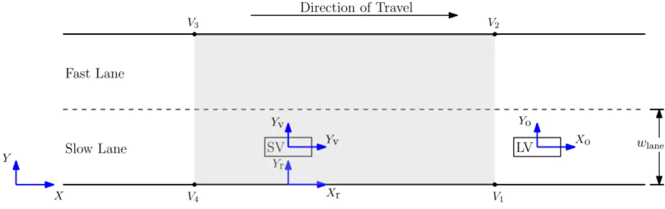
3.1 Road setup: coordinate frames and range of local risk map . . . 32
3.2 Kinematic bicycle model . . . 33
3.3 Schematic to explain identification of collision avoidance zone. Note:
SV−blue rectangle, LV and surrounding unsafe region−red poly-gon, target coordinate−magenta cross, safe zone−green polygon . 47
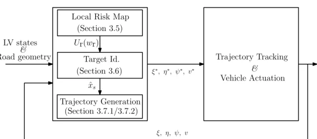
3.4 Closed-loop framework for trajectory planning. Note: LV denotes lead vehicle . . . 50
3.5 Error polyhedron and resulting tightened input set obtained by chang-ing magnitude of eigenvalue . . . 55
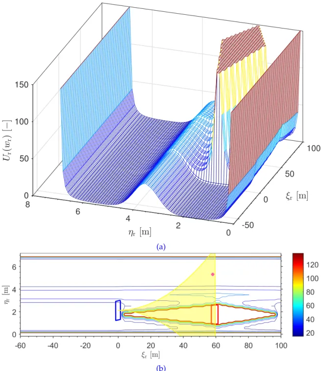
3.6 Snapshot of simulation (simulation time t = 14 s); (a) Cumulative potential fieldUr from road, lane, and obstacle vehicle; (b) Contour
plot of the potential field along with the reachable set (yellow) and reference target on the road (magenta cross). Note: Blue rectangle depicts the subject vehicle and the rectangle in red depicts the lead vehicle . . . 57
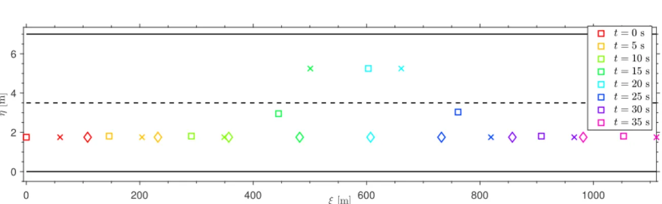
3.7 Snapshot of simulation demonstrating: reference targets(×)for dif-ferent configurations of subject vehicle()and lead vehicle(♦)while driving on a highway. Note: solid lines (–) are the road boundaries and dashed line (- -) is the lane marking . . . 58
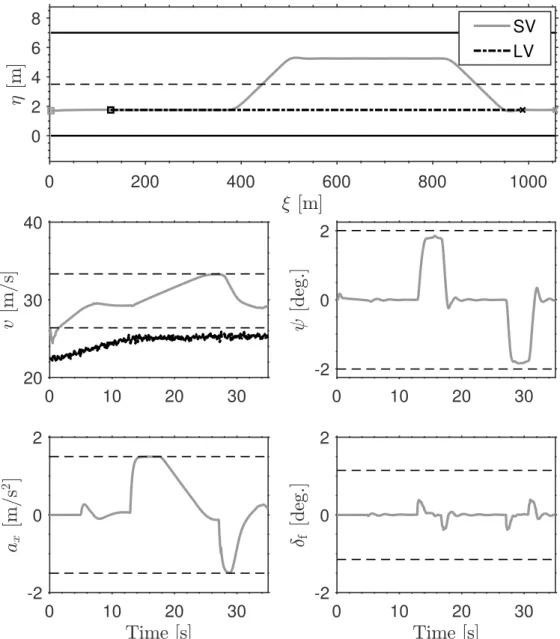
3.8 Simulation results: SV and LV trajectories, longitudinal velocity, head-ing angle, longitudinal acceleration, and steerhead-ing angle for a high-speed overtaking manoeuvre. Note:(- -) are the system constraints . 59
3.9 Simulation results: trajectory of the subject vehicle (SV) during an overtaking manoeuvre in the lead vehicle (LV) frame of reference (ξo,ηo). . . 60
4.1 EMRAC control scheme [140] . . . 66
4.2 Overview of path-tracking model. Note: Reference path (black-dashed) 78
4.3 Reference road curvature and longitudinal velocity for hypothetical highway driving scenario (Manoeuvre I) . . . 81
4.4 Evolution ofKX,KR, andKIfor hypothetical highway driving scenario
(Manoeuvre I) . . . 82
4.5 Evolution of ||φ||and ||φN|| for hypothetical highway driving
sce-nario (Manoeuvre I).Note: Unbounded switching action (Red), gain of the switching action bounded byσ-modification (Blue-dashed) . . 83
4.6 Dynamics of system for hypothetical highway driving scenario (Ma-noeuvre I). Note: Unbounded switching action (Red), gain of the switching action bounded byσ-modification (Blue dashed), reference
model (solid black) . . . 84
4.7 Evolution of state errors for hypothetical highway driving scenario (Manoeuvre I).Note: Unbounded switching action (Red), gain of the switching action bounded byσ-modification (Blue-dashed), reference
model (Solid black) . . . 85
4.8 Net control action for hypothetical highway driving scenario (Ma-noeuvre I). Note: Unbounded switching action (Red), gain of the switching action bounded byσ-modification (Blue-dashed) . . . 86
4.9 Dynamics of system for driving in crosswinds (Manoeuvre II).Note:
Uncontrolled (Grey), Switching action bounded by σ-modification
(Blue-dashed) . . . 88
4.10 Evolution of||φN||and control input for driving in crosswinds
(Ma-noeuvre II) . . . 89
4.11 Reference road curvature for lane changes in low friction (Manoeuvre III) . . . 89
List of figures
4.12 Dynamics of system for lane changes in low friction (Manoeuvre III).Note: Nominal conditions (Grey-dashed), low-friction and extra passengers (Blue) . . . 91
4.13 Evolution of state errors for lane changes in low friction (Manoeuvre III).Note: Nominal conditions (Grey-dashed), low-friction and extra passengers (Blue) . . . 92
4.14 Evolution of ||φN|| and control input for lane changes in low
fric-tion (Manoeuvre III).Note: Nominal conditions (Grey-dashed), low-friction and extra passengers (Blue) . . . 93
5.1 Schematic of a steering actuator system illustrating the input and output interfaces . . . 101
5.2 Frequency-domain response of steering dynamics with exact and approximated delays. . . 102
5.3 Desired lateral and longitudinal signals for Gaydon test-track; (a) path curvatureκdes; (b) longitudinal velocityvdes . . . 105
5.4 Geometric representation of reference curvature generation from given desired path (grey) . . . 105
5.5 Closed-loop control structure: combined local path planning&tracking107
5.6 Evolution of the EMRAC states and errors for driving on test-track. Note: reference model (red), system states (blue), error between refer-ence model and system (orange) . . . 109
5.7 Simulation results; (a) path coordinatesp; (b) curvatureκas a function
of distance travelled along path; (c) longitudinal velocityvover time 110
5.8 Simulation results for tracking desired path; (a) front wheel steering angleδf; (b) norm of switching action||φN|| . . . 111
5.9 Comparison of simulation results for tracking desired coordinates with variation in delay of steering actuator system ¯τsa; (a) front wheel
steering angleδf; (b) cross track errorηxt . . . 113
5.10 Geometric representation of reference curvature generationfrom RMPC optimal trajectory. Note: Green dots represent the reference coordi-nates p∗ra = (ξra∗,ηra∗)for the rear-axle of the SV . . . 114
5.11 Proposed closed-loop control architecture for autonomous overtaking: combined trajectory planning&tracking . . . 115
5.12 Simulation Results: SV and LV trajectories, longitudinal velocity v, heading angleψ, longitudinal accelerationax, and steering angleδf
for a high-speed overtaking manoeuvre. Note: (- -) are the system constraints . . . 118
5.13 Simulation Results: comparison of reference curvatureκref and SV’s
estimated curvatureκ≈rz/vduring the overtaking manoeuvre . . . 119
5.14 Simulation results, evolution of the internal states of the EMRAC controller during the overtaking manoeuvre; (a) lateral velocity vy;
(b) yaw-raterz; (c) lateral errorηe; (d) heading angle error ψe . . . 121
5.15 Simulation results: trajectory of the subject vehicle (SV) during an overtaking manoeuvre in the lead vehicle (LV) frame of reference (ξo,ηo). . . 122
5.16 Simulation results: evolution of the lateral accelerationayof the
sub-ject vehicle (SV) during an overtaking manoeuvre. . . 123
5.17 Simulation results, comparison while overtaking in nominal and low-friction conditions; (a) control action δf; (b) norm of gain for
continuous part of control action||φ||; (c) norm of gain for switching
action||φN|| . . . 125
B.1 Schematic of a prediction model . . . 155
E.1 Frequency Response Function: steering angleδfto lateral velocityvy 163
E.2 Frequency Response Function: steering angleδfto yaw-raterz . . . . 164
F.1 Look-ahead distanceξlaand lateral errorηe,laat look-ahead point . . 165
F.2 Poles and Zeros of the system Gyu(s)with vx,nom = 15.27 m s−1 for
different look-ahead distances . . . 166
F.3 Poles and Zeros of the system Gyu(s)with vx,nom = 29.18 m s−1 for
List of tables
1.1 SAE J3016™: Levels of driving automation [4] . . . 2
2.1 Summary of techniques for trajectory planning to avoid a moving obstacle . . . 19
2.2 Summary of control strategies for vehicle trajectory tracking [79,82,
86,87,89] . . . 24
A.1 Design Parameters: Environment and Situational Awareness . . . 151
A.2 Design Parameters: Robust MPC for Trajectory Planning . . . 152
A.3 Design Parameters: EMRAC for lateral tracking . . . 152
A.4 Design Parameters: EMRAC for lateral tracking: Test-track . . . 153
Nomenclature
Roman Symbols ˆ
x Target state vector
B(·,·) set representing an open ball with given centre and radius
G set of safe coordinates around subject vehicle
R finite time reachability set of a system
S set of Lebesgue measure zero
U closed set representing the input constraints
W closed set representing bounded disturbance
X closed set representing the state constraints
Z closed set representing error bounds
F discontinuous vector field
A system matrix of a state-space system
a(·) coefficient ofxin the general form of equation of a line
Am system matrix of EMRAC reference model
ax longitudinal acceleration [m s−1]
B input matrix of a state-space system
b(·) coefficient ofyin the general form of equation of a line
Bm input matrix of EMRAC reference model
C output matrix of a state-space system
C(·) equivalent lateral stiffness of axle [N rad−1]
c(·) coefficient in the general form of equation of a line
d bounded disturbance signal
d(·) distance from the centre of rear-axle along the longitudinal axis of the vehicle [m]
e error vector
f vector space map
Iz moment of inertia aroundz-axis [kg m2]
KΩ nominal controller for terminal set
KFB∗ feedback control gain of EMRAC reference model KFF∗ feedforward control gain of EMRAC reference model KI integral control gain
KN switching control gain
KR feedforward control gain
KX feedback control gain
l(·) distance of axle from center of gravity [m]
M mass of vehicle [kg]
N Prediction Horizon
Nc Control Horizon
P solution of Lyapunov equation
p point in a two dimensional coordinate space Q weighting matrix for state cost
R weighting matrix for input cost
r reference signal
R(·) radius of curvature of path [m]
rz yaw-rate [rad s−1]
T weighting matrix for terminal state cost
t time vector
ts sampling time
u input vector
Ui stack of control inputs
Ur net potential in road frame of reference
Nomenclature
Ulane lane potential
Uroad road potential
Uvel lane velocity potential
V Lyapunov Function
v velocity [m s−1]
VN Performance Index/Cost Function
vy lateral velocity [m s−1]
w bounded process-disturbance vector
wlane width of a lane [m]
x state vector
Xi stack of predicted states
y output vector
ye output error
Greek Symbols
α(·) weight for the integral part of the adaptive gain
¯
τsa time delay of nominal steering actuator system [s]
β vehicle side-slip angle [rad]
β(·) weight for the proportional part of the adaptive gain
δ steering angle [rad]
η lateral position [m]
ηxt cross-track error [m]
ηe,la lateral error between desired path and vehicle’s longitudinal axis at look-ahead point
[m]
ηe lateral position error [m]
κ path curvature
λ eigenvalue
µroad,ref reference friction coefficient of road surface
µroad friction coefficient of road surface
Φ prediction matrix for state propagation φ(·) integral part of adaptive gain
Ψ prediction matrix for input propagation
ψ heading angle [rad]
ψe heading angle error [rad]
ρ combined vector space of states and inputs
τ torque [N]
τsa time delay of steering actuator system [s]
θ sub-space of steady-states and inputs
ξ longitudinal position [m]
Subscripts
0 initial value
max maximum limits
min minimum limits
des desired value
f front r rear a augmented ca collision avoidance c in continuous-time domain d in discrete-time domain
path pertaining to path tracking model
ss steady-state
t related to terminal set/state
x along longitudinal axis
y along lateral axis
la look ahead
ref reference signal
sa steering actuator
xt cross-track
Acronyms / Abbreviations
Nomenclature
ABS Anti-lock Braking System ACC Adaptive Cruise Control
ADAS Advanced Driver-Assistance Systems
AEB Automated Emergency Braking
AFS Active Front Steering
C.G Center of Gravity
CACC Cooperative Adaptive Cruise Control DARPA Defense Advanced Research Projects Agency DLC Discretionary Lane Change
dof degree of freedom
dv decision variable
dv decision variable
ECU Electronic Control Unit
EMRAC Enhanced Model Reference Adaptive Control GNC Guidance and Navigation Control
I&I Inversion & Immersion
LDM Local Dynamic Map
LiDAR Light Detection And Ranging LPV Linear Parameter Varying LQR Linear Quadratic Regulator
LTV Linear Time Varying
LV Lead Vehicle
MIMO Multi-input Multi-output
MLC Mandatory Lane Change
MPC Model Predictive Control
MRAC Model Reference Adaptive Control
par parameter
par parameter
PID Proportional Integral Derivative PID Proportional Integral Derivative
Radar Radio Detection And Ranging RMPC Robust Model Predictive Control RRT Rapidly-exploring Random Tree
SCMPC Scenario-based Model Predictive Control SIMO Single-input Multi-output
SMC Sliding Mode Control
SV Subject Vehicle
TTC Time-to-Collision
TV Traffic Vehicle
Chapter
1
Introduction
अकमेणानुपायेन कमार्रभो न िसयित ।।२६।।
–तोपायानम ्
A work begun with no order and means does not succeed.
– Tantropākhyāna 26
1.1
Motivation
A
confluence of personal passion towards cars and a desire to better current and future vehicles through meaningful contributions in vehicle dynamics&control is the motivation behind this thesis.
With substantial improvements being made across the board in sensors capabili-ties, computing performance, communication systems, advanced control techniques, etc. the first two decades of the 21st century have given a great boost to the de-velopment of intelligent vehicles. The rate of progress in the field of intelligent transportation systems has been rapid and quickly jumped from providing only assistance during certain times (e.g., ABS, traction control, etc.) to more advanced capabilities such as lane-keeping, automated parking, assisted lane changing, emer-gency braking, reading road signs, etc. Moreover, many of the premium series production vehicles provide self-driving capabilities under certain scenarios such as driving in slow moving traffic up to 60 km h−1, park and summon from parking lots, advanced highway cruising capabilities, etc. making SAE level 2 of autonomy already available to the customer and deployed in real world scenarios, see Table1.1. These features primarily rely on a vehicle’s on-board sensor suite (e.g., RADAR, vision, LiDAR, and ultrasound) to gain awareness of its environment and use this information as input to advanced algorithms to continuously monitor and update steering, acceleration, and braking levels for performing the semi-autonomous capa-bilities mentioned above. As is natural for any technological endeavour, the next steps for engineers and researchers alike is to unlock level 3 and 4 of automation
keeping in mind the eventual goal of full autonomy i.e., SAE level 5. Moreover, it is important to be cognizant of the fact that the solutions and systems proposed to achieve any kind of autonomy should be scalable from prototype vehicles to millions of vehicles plying on public roads. Therefore, the safety and reliability of autonomous vehicles needs to be proactively illustrated. To achieve comparable failure rates as the aircraft industry, then the safety goal for autonomous vehicles is to have a mean time between catastrophic failures of 109h [1]. The ISO 26262 standard provide a standardised and widely accepted practice that provides a methodical verification and validation procedure to ensure automotive safety [2]. However, the ISO 26262 standard does not cover all aspects for mapping the various aspects of an autonomous vehicle within its verification and validation framework. A comprehen-sive review of the unique challenges for verification and validation of autonomous vehicles and the mapping of the technical aspects to the ISO 26262 standard are provided in [3].
Table 1.1SAE J3016™: Levels of driving automation [4]
SAE Automation Levels Description
0 – No Automation The full-time performance by the human driver of all aspects of the dynamic driving task, even when enhanced by warning or intervention systems.
1 – Driving Assistance The driving mode-specific execution by a driver assistance system of either steering or acceleration/deceleration using information about the driving environment and with the expectation that the human driver perform all remaining aspects of the dynamic driv-ing task.
2 – Partial Automation The driving mode-specific execution by one or more driver assis-tance sysetms of both steering or acceleration/deceleration using information about the driving environment and with the expecta-tion that the human driver perform all remaining aspects of the driving task.
3 – Conditional Automa-tion
The driving mode-specific performance by an automated driving system of all aspects of the dynamic driving task with the expecta-tion that the human driver will respond appropriately to a request to intervene.
4 – High Automation The driving mode-specific performance by an automated driving system of all aspects of the dynamic driving task, even if a human driver does not respond appropriately to a request to intervene. 5 – Full Automation The full-time performance by an automated driving system of
all aspects of the dynamic driving task under all roadway and environmental conditions that can be managed by a human driver.
The next set of self-driving capabilities that need to be achieved involve ma-noeuvres at higher vehicle speeds, greater interaction with other participating traffic
1.2 Objectives
members, increased operating range, all weather capability, etc. However, manoeu-vres with higher speeds and increased traffic interaction are inherently complex and thus require a renewed focus on safety of all road participants and requirements such as all weather capabilities highlighting the need for feasibility of the system at all times. It is also noteworthy that gaining the ability to operate safely in diverse environments is highly beneficial as it provides self-driving capabilities to a larger set of users to operate the vehicles in varied operating conditions.
Overtaking slower moving traffic vehicles in high-speed environments such as highways is one such manoeuvre that requires precise control of the lateral and longitudinal motion of the vehicle at high-speeds while ensuring all safety considerations are met and occupant comfort is not sacrificed. Furthermore, gaining the ability to overtake autonomously will not only allow a vehicle to travel further down the road without the need of human intervention but also pave way for performing other tasks such as merging and leaving a highway, collision avoidance, etc.
1.2
Objectives
The aim of this thesis is to improve the autonomous driving capabilities of a vehicle in high-speed environments. The objective is to understand how to design controllers for motion control of a vehicle to perform high-speed manoeuvres autonomously. This leads to the main objective of this research.
Design& develop a closed-loop control architecture that enables a vehicle to perform overtaking manoeuvres at high-speeds in a safe and acceptable manner.
Since, planning and controlling the combined lateral and longitudinal motion of a vehicle is a complex and safety critical task, the approach taken is to tackle it in a sequential manner. The first aspect is to study the immediate surrounding of the vehicle and generate collision-free and feasible trajectories to perform an overtaking manoeuvre. This leads to the following objective
Develop a trajectory planning framework to generate collision-free and feasible trajectories for high-speed overtaking.
Controlling the steering angle of a vehicle to follow a given path is a complex challenge due to the myriad interactions between road, environment, and vehicle systems. This results in the following objective for control of steering angle to track a given path
Design a generic steering controller for trajectory tracking to perform typical highway driving manoeuvres.
Finally, the trajectory planning and trajectory tracking controller need to be combined seamlessly to achieve an integrated solution that allows a vehicle to plan and track trajectories to perform an overtaking manoeuvre. This integration should be such that the individual performance characteristics of the controllers are not compromised. Thus, this leads to the following objective
Combine the planning and tracking controller to formulate an integrated motion control archi-tecture with the capability of performing a high-speed overtaking manoeuvre autonomously.
1.3
Outline
&
Contributions
This section provides a brief outline of the thesis. Additionally, the aim of the work in each chapter and relevant contributions to the field are summarised.
Key takeaways from relevant research work pertaining to the topic of trajec-tory planning, trajectrajec-tory tracking for high-speed autonomous vehicles is discussed in Chapter 2. The review helped in comparing the different approaches for tra-jectory planning& control based on aspects such as feasibility, design approach, performance, etc. Moreover, the review highlighted the need for an autonomous overtaking system that provided safe, dependable, and robust operation by con-sidering vehicle dynamics, environmental conditions, etc. This chapter is based on:
• Dixit, S., Fallah, S., Montanaro, U., Dianati, M., Stevens, A., Mccullough, F. and Mouzakitis, A. Trajectory planning and tracking for autonomous overtaking: State-of-the-art and future prospects. Annual Reviews in Control, 45 (2018), pp.76-86.
In Chapter 3, the design of a modular framework for trajectory planning to perform high-speed overtaking is discussed. The framework consists of an artificial potential field based situational awareness functionality to identify safe driving zones coupled to a model predictive control approach for generating feasible trajec-tories to steer the vehicle through the safe zones. Simulation studies are performed to demonstrate the ability of the proposed closed-loop framework to generate fea-sibble and safe trajectories for autonomous overtaking even when the velocity of the subject vehicle is not constant. This chapter is based on:
• Dixit, S., Montanaro, U., Dianati, M., Oxtoby, D., Mizutani, T., Mouzakitis, A. and Fallah, S. Trajectory Planning for Autonomous High-Speed Overtaking in
1.3 Outline&Contributions
Structured Environments Using Robust MPC.IEEE Transactions on Intelligent Transportation Systems (2019).
• Dixit, S., Montanaro, U., Fallah, S., Dianati, M., Oxtoby, D., Mizutani, T. and Mouzakitis, A. Trajectory Planning for Autonomous High-Speed Overtaking using MPC with Terminal Set Constraints. In2018 21st International Conference on Intelligent Transportation Systems (ITSC)(pp. 1061-1068). IEEE.
• Trajectory planning framework is subject to patent under UKIPO GB1801968.7 (under review)
Chapter4is based on the design of a generic lateral tracking controller to follow reference curvatures at high-speeds. The enhanced model reference adaptive control has been utilised and the issue of the unbounded gain for the switching action has been systematically tackled with a σ-modification strategy. The closed-loop
system has been proven to be ultimate bounded through the use of an extended Lyapunov theory for discontinuous systems with the aim of ensuring the closed-loop dynamics of the vehicle follow a given reference model despite model miss-matches, uncertainties, and disturbances acting on the system. The proposed controller is numerically validated in a high-fidelity simulation environment to demonstrate its ability to accurately track reference curvatures that are typical for highway driving. This chapter is based on:
• Dixit, S., Montanaro, U., Fallah, S., Dianati, M. and Mouzakitis, A. Integral MRAC with Bounded Switching Gain for Autonomous Vehicle Lateral Track-ing. IEEE Transactions on Control Systems Technology. (undergoing revisions).
In Chapter5, the trajectory planning& tracking controllers are combined to realise a hierarchical closed-loop architecture for autonomous high-speed overtaking. Moreover, the steering actuator dynamics are also included within the design of the tracking controller to compute more realistic control signals. The resultant closed-loop architecture is numerically validated by simulation studies and it shown to be an effective method for performing overtaking manoeuvres even in severe weather conditions. This chapter forms the basis for an academic paper that is in preparation to be submitted for publication in a peer-reviewed journal.
The conclusions of the work and recommendations for future research directions are presented in Chapter6.
In addition to the contributions presented above, close collaboration with research colleagues also resulted in the following publications.
• Taherian, S., Montanaro, U.,Dixit, S.and Fallah, S. Integrated Trajectory Plan-ning and Torque Vectoring for Autonomous Emergency Collision Avoidance. In2019 22nd International Conference on Intelligent Transportation Systems (ITSC)
(pp. 2714-2721). IEEE.
• Montanaro, U., Dixit, S., Fallah S. Adaptive Control and Robust MPC for Linearising Longitudinal Vehicle Dynamics for Platooning Applications. In
2019 26th IAVSD Symposium on Dynamics of Vehicles on Roads and Tracks (IAVSD).
• Montanaro, U., Dixit, S., Fallah, S., Dianati, M., Stevens, A., Oxtoby, D. and Mouzakitis, A. Towards connected autonomous driving: review of use-cases.
Chapter
2
Background
&
Literature Review
यतु संचरते देशान ्यतु सेवेत पिण्डतान ्।तय िवतािरता बुिधतैलिबुिरवाभिस ॥११:८९॥
–सुभािषत मंजरी The intelligence of a person who travels in different countries and associates with
scholars expands, just as a drop of oil expands in water.
– Subhāṣita Maṁjarī 11:89
Trajectory planning and trajectory tracking constitute two important functions of an au-tonomous overtaking system and a variety of strategies have been proposed in the literature for both functionalities. However, uncertainties in environment perception using the current generation of sensors has resulted in most proposed methods being applicable only during low-speed overtaking. In this chapter, trajectory planning and trajectory tracking approaches for autonomous overtaking systems are reviewed. The trajectory planning techniques are com-pared based on aspects such as real-time implementation, computational requirements, and feasibility in real-world scenarios. This review shows that two important aspects of trajectory planning for high-speed overtaking are: (i) inclusion of vehicle dynamics and environmental constraints and (ii) accurate knowledge of the environment and surrounding obstacles. The review of trajectory tracking controllers for high-speed driving is based on different categories of control algorithms where their respective advantages and disadvantages are analysed. This study shows that while advanced control methods improve tracking performance, in most cases the results are valid only within well-regulated conditions. Therefore, existing autonomous overtaking solutions assume precise knowledge of surrounding environment which is not representative of real-world driving. The chapter also discusses how in a con-nected driving environment, vehicles can access additional information that can expand their perception. Hence, the potential of cooperative information sharing for aiding autonomous high-speed overtaking manoeuvre is identified as a possible solution.
2.1
Introduction
M
ODERN cars are equipped with various sensors and electronic systems to reduce the workload of a driver by providing emergency assistance (e.g., ABS, traction control, stability control, etc.), ADAS (e.g., cruise control, lane keeping, crosswind assistance, blind spot detection, etc.), and navigational assistance (e.g., trip planning, route selection, regular traffic update, etc.). However, the next generation of intelligent vehicles are expected to have increased capabilities which allow automated manoeuvring in various driving scenarios [6,7]. Overtaking is one of the most common driving manoeuvre and any vehicle capable of end-to-end autonomy must have the ability to determine if, when, and how to perform this driving task.Overtaking is a complex driving task as it involves both lateral and longitudinal motions of an overtaking vehicle (subject vehicle) while avoiding collisions with a slower moving vehicle (lead vehicle) [8]. Additional complexity arises due to different environmental conditions (e.g., road legislations, visibility, weather, etc.) and diversity of road-users (e.g., small cars, buses, trucks, etc.) [9]. Typically, an overtaking manoeuvre is considered successful on proper completion of three sub-manoeuvres namely, (i) lane change to overtaking lane, (ii) pass lead vehicle(s), and (iii) lane change back to original lane [10]. The lane change sub-manoeuvre which indicates the start and the end of an overtake can be classified under two categories; (i) Discretionary Lane Change (DLC) and (ii) Mandatory Lane Change (MLC) [11]. A DLC sub-manoeuvre is performed when the immediate traffic situation in the faster lane is deemed to be better than the current lane and thus, the lane change is performed in anticipation of an improvement in the immediate driving conditions. On the other hand, an MLC sub-manoeuvre is performed due to compulsion arising from traffic rules (e.g., stalled vehicle, need to follow desired route, etc.). Moreover, the lane change to return back to the original lane can also be either DLC or MLC based on traffic conditions in each lane, legislation, etc. thus, transforming an over-taking manoeuvre into a complex task of dynamically choosing the best driving lane based on (i) legislation, (ii) driving intentions, and (iii) instantaneous traffic situation. This inference that the choice of lane is affected by both; (i) driving intention, and (ii) neighbourhood traffic conditions was verified in [12] using an integrated model (combining MLC and DLC) for lane changing behaviour based on gap acceptance (lead and lag gap). Therefore, it is noted that due to the dynamic nature of driving environments (i.e., traffic conditions in original and fast lane, speed limits, road conditions, etc.) overtaking is not standardised manoeuvre and thus, each
2.1 Introduction
taking manoeuvre in real-world scenarios is unique. This uniqueness arises from variations in number of overtaken vehicles, duration of overtake, relative velocity between concerned vehicles, distance between concerned vehicles, etc. [13–20]. For an autonomous vehicle, feasibility of an overtaking manoeuvre is evaluated on the basis of safety based on subject vehicle’s states as well as surrounding information leading to a discrete outcome for making tactical decisions (i.e., either perform lane-change or do not perform lane lane-change) which form a part of planning and decision making process. A variety of techniques for decision making are available in litera-ture with (i) multi-level decision trees [21], (ii) probabilistic weighted comparison of concurrent goals [22], and (iii) higher award seeking Markovian Decision Process algorithms [23] being among the prominent methods.
A schematic representation of an overtaking manoeuvre is shown in Figure2.1
with each sub-manoeuvre labelled with roman numerals. As discussed above, the lane change back to the original lane depends on the traffic conditions and thus both possibilities are depicted in the schematic. Despite the innumerable variations present due to the factors discussed above, overtaking manoeuvres can be classified under the four categories listed below [15]:
• Normal: The subject vehicle approaches the lead vehicle and waits for a suitable opportunity to perform the manoeuvre
• Flying: The subject vehicle does not adjust its longitudinal velocity and is directly able to overtake the lead vehicle
• Piggy backing: The subject vehicle follows a preceding vehicle as they both overtake the lead vehicle
• 2+: The subject vehicle overtakes two or more lead vehicles in a single ma-noeuvre
For the aforementioned scenarios, the duration of a completed overtake has been found to be in the range of 5.4 s to 12.5 s (subject to dynamic nature of the surrounding traffic and environment) using records of the trajectories of vehicles on typical European highways [8,19,24–28]. Performing an autonomous overtaking manoeuvre based on any of the scenarios mentioned above within a given time range requires accurate information of surrounding environment, traffic, and weather conditions along with sophisticated sensing and perception, planning, and control systems [29]. The surrounding environment of a vehicle is populated by different features; (i) permanent (road and lane limits), (ii) slowly changing (e.g., temporary speed limits, road works, traffic density, etc.), and (iii) fast changing (surrounding
SV LV
safe approaching distance safe merging distance
safe lateral distance Direction of Travel
(i)
(ii)
(iii.a)
(iii.b)
Traffic
Figure 2.1 Basic schematic of an overtaking manoeuvre. Note: Different sub-manoeuvres are (i) lane-change; (ii) pass lead vehicle; (iii.a) merge back into original lane; (iii.b) continue in faster lane to pass traffic
vehicle velocity, position, heading, etc.). A modern day vehicle uses a host of on-board sensors to discern the environment and the placement of an on-on-board sensor suite used to perform this task can be seen in Figure2.2. The information from these sensors is combined and used for tasks such as; (i) classify objects, (ii) track stationary and moving obstacles, (iii) identify safe driving zones, etc. Currently, there are some production vehicles that utilise vehicle-to-everything (V2X) information to provide updates on permanent (e.g., road and lane limits, road inclination, etc.) or slowly changing features (e.g., temporary speed limits, road works, traffic updates, etc.) of surrounding environment via a combination of cellular data and Local Dynamic Map (LDM) updates. However, despite an elaborate sensor suite and first generation V2X communication systems the capabilities of the contemporary autonomous vehicles is limited to low-speed overtaking. This is due to limitations such as; (i) range of sensors, (ii) blind spots , (iii) small time-scales for predicting motion of traffic participants, (iv) sensor imperfections, and (v) possible V2X network outages. The combination of one or more of these limitations result in significant uncertainty while planning complex highway manoeuvres (e.g., overtaking) which span several seconds at high-speeds [30,31]. Moreover, unless all the traffic participants are connected and autonomous the uncertainty arising from predicting the motion of traffic vehicles cannot be brought down to negligible levels even with the advent of perfect on-board sensors and/or V2X communication network. Thus, predicting the motion of traffic participants for risk assessment forms a vital part of manoeuvre planning and this domain has witnessed a lot of research and a large number of techniques are present in literature. The different methods for motion planning for intelligent autonomous vehicles based on abstraction levels of traffic motion are classified as; (i) physics-based [32–34], (ii) manoeuvre-based [35], and (iii) interaction-aware [36,37]. A comprehensive survey discussing the advantages and limitations
2.1 Introduction 250 m 90 m 70 m 4.5 m 40 m 80 m STEREO CAMERA
MULTI MODE RADAR LONG RANGE RADAR
250 m range/opening angle 20o
70 m range/opening angle 90o
3D capability over a range of 90 m/opening angle 50o 80 m range/opening angle 30o 40 m range/opening angle 140o ULTRASONIC SENSORS 1.5/4.5 m range SV TV TV TV
Figure 2.2Visibility of an autonomous vehicle.Note: SV: Subject Vehicle, TV: Traffic Vehicle. Sensor performance specifications are based on [39]
of each of these techniques is presented in [38] and an interested reader is directed towards it.
Recent research has highlighted the potential use of off-board information via V2X communications in expanding the sensory and perception horizon of a vehicle through the communication systems [40–42]. In the context of autonomous overtak-ing, initial research has been largely focused on the integration of V2X information to: (i) manoeuvre feasibility check, and (ii) decision making stages [14,15,40]. However, the potential enhancements that can be achieved in trajectory planning and trajec-tory tracking of an overtaking manoeuvre by exploiting V2X information are yet to be studied. In this chapter, a review of various techniques for trajectory planning and trajectory tracking for autonomous overtaking systems is presented. The aim is twofold: (i) to gain insight on techniques suitable for autonomous overtaking systems, and (ii) to investigate how V2X information can enhance both trajectory planning and tracking techniques of an autonomous overtaking system.
The chapter is structured as follows: Section2.2introduces the system overview of an autonomous driving system and discusses how a two-tier control architecture can be used to perform autonomous overtaking. In Section2.3, an extensive literature review of trajectory planning methods used for generating overtaking trajectories is presented. Comparison of key aspects pertaining to vehicle models and a review of different control strategies for trajectory tracking applications is performed in Section2.4. Finally, the findings from the chapter are summarised in Section2.5.
2.2
System Architecture
An autonomous overtaking manoeuvre requires consideration of a variety of factors such as subject vehicle states and constraints, lead vehicle states, environment limits, safety, and comfort. An overview of an intelligent autonomous driving system capable of performing autonomous overtaking is shown in Figure2.3. For an au-tonomous vehicle to successfully perform different tasks (e.g., lane change, pass lead vehicle, and merge) pertaining to overtaking, it is expected that the vehicle can carry out each sub-task within the sensing and perception, planning, and control blocks. Sensing and perception includes gathering information about the driving conditions to determine if and when the conditions are favourable to perform the overtaking [25]. An autonomous vehicle utilises information from on-board sensors (Radar, LiDAR, camera, etc.) and/or off-board information via V2X communica-tions to generate a real-time environmental representation [43], see Figure2.3. The main objectives of the sensing and perception system are combining (fusing) data from different sensors, lane-level localisation, neighbouring vehicle detection, static obstacle/constraint detection and safe drivable area representation [43].
The planning module utilises the perception information along with the subject vehicle states and dynamic constraints to compute safe collision free local trajectory for the subject vehicle at each time instant [44]. To plan an overtaking manoeuvre the vehicle uses perception data (position and velocity estimates of neighbouring vehicles, infrastructure limits, road geometry, headway time) and subject vehicle data (current state, lateral and longitudinal dynamics) to check feasibility of the manoeuvre and design a collision free and safe local reference trajectory for an overtaking manoeuvre [8,20,45–49].
The local trajectory generated via the planning module is used as a reference trajectory to be tracked while performing an overtake (e.g., lane change, pass lead vehicle, lane-merge), and a closed-loop control system is designed to track it by controlled manipulation of steering, throttle and/or brake [8,10,20,45,46,48,50–
53].
To preserve the modular nature of the architecture presented in the section above, the different driving tasks can be translated to a control architecture for an au-tonomous vehicle as shown in Figure2.4, i.e. trajectory planning controller and trajectory tracking controller [43,48,54–56]. The objective of the trajectory planning controller is to perceive the environment, monitor vehicle states (longitudinal and lateral positions, longitudinal and lateral velocities, longitudinal and lateral acceler-ations, heading, and yaw-rate) and compute safe trajectories for the vehicle to track [47]. The trajectory tracking controller then computes, via feedback algorithms based on the tracking error, the necessary torque (τref) and steering inputs (δref) required
2.3 Trajectory Planning
Data Processing
Send/Receive Sensors
Sensing and Perception
Planning/Decision
Control
Collision Free Trajectory Vehicle
V2X
Environment Representation
Local Reference Trajectory
Trajectory Tracking Controller
Actuators Actuator Inputs Path Planner Off-board Situational Awarness Dynamics data
Figure 2.3Overview of an autonomous driving system
to track the reference, despite possible measurement noise, un-modelled dynamics, parametric uncertainties which may or may not be accounted for by the trajectory planning controller.
2.3
Trajectory Planning
An autonomous vehicle relies on real-time vehicle state and environment informa-tion (e.g., surrounding vehicles, road condiinforma-tions) to derive a local trajectory that
Vehicle Trajectory tracking control
Inner-loop Control
Estimation τref
δref
Trajectory planning control
Trajectory Update Localization LDM GPS V2X vref ξref, ηref longitudinal speed & Actuation
e.g., yaw-rate, acceleration, velocity, etc. e.g., heading angle, position, etc.
reference (vx,des)
Figure 2.4General control architecture for an autonomous vehicle [43,48,54–56]. (V2X block with dot-dash boundary: optional functionality)
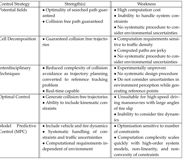
ensures a safe passage while minimising the deviation from the overall journey trajectory (global trajectory). Local trajectory planning can be defined as−real-time planning of the vehicle’s transition from one feasible state to the next while satisfying the vehicle’s kinematic limits based on vehicle dynamics and constrained by occupant comfort, lane boundaries and traffic rules, while, at the same time, avoiding obstacles[44]. Technical literature shows that the vast majority of trajectory planning methods for an overtak-ing application employ one of the four well known techniques i.e., potential fields, cell decomposition, interdisciplinary methods and optimal control. In this section, these techniques are reviewed to gain insight into their performance for different specifications such as computational requirements, safety, feasibility in high-speed overtaking and real-time implementation.
Potential field algorithms assign repulsive fields to obstacles and attractive fields to safe zones of the vehicle and then use an algorithm to compute trajectories along the steepest potential gradient in the resulting field [47,48], see Figure2.5(a). The computed path is guaranteed to follow the lowest potential (i.e., find collision free trajectory) in a given space but its safety and accuracy depends heavily on the accuracy of the generated potential field (i.e., definite knowledge of position of stationary and moving obstacles). However, due to the high computation costs and need for very accurate surrounding environment information, the method has only been experimentally verified for low speed (i.e., urban) manoeuvres [48]. Additionally, since potential field based algorithms optimise for a collision-free path without considering the system dynamics and kinematic constraints, the generated trajectories might be unfeasible which results in safety concerns for high-speed driving scenarios [47,57].
Cell decomposition algorithms such as Rapidly-exploring Random Tree (RRT) is a method used for collision free path planning [58,59], see Figure2.5(b). In this
2.3 Trajectory Planning
algorithm, a tree is incrementally constructed from a given initial configuration (source cell) by creating connections to neighbouring cells which lie outside of an obstacle. The search ends when the goal (target cell) is reached and parsing this tree to obtain the shortest path from the source cell to the target cell provides a collision-free reference trajectory for an autonomous vehicle to follow. These algorithms can be modified to incorporate the vehicle constraints but they also suffer from computational and memory costs [47,58,59]. The computational complexity of such algorithms increases with increasing traffic density and frequency of road curvature thus jeopardizing the on-board computation of an autonomous vehicle on busy roads [58]. Furthermore, the paths created by RRT’s are jerky and tracking such a trajectory will have an adverse effect on the comfort of the occupants [44].
Inter-disciplinary techniques inspired by robotics and missile guidance systems [10,60,61] for vehicle path-planning are also reported in literature. One of the novel approaches proposed was to use motion primitives (combination of steady-state equilibrium trajectories and pre-specified manoeuvres) [62]. The experimental re-sults demonstrated that collision free and feasible trajectories can be generated in real-time using this approach [62]. Ghumman et al. designed a trajectory planning method based on Rendezvous Guidance technique (passing vehicle is guided in real-time to match the position and velocity of a shadow target during an overtak-ing manoeuvre) inspired from missile guidance systems [60,61], see Figure2.5(c). Similarly, an approach for overtaking manoeuvre consisting of consecutive tracking of virtual reference points positioned a priori at known distances from the lead vehi-cle is proposed in [10]. Simulation results of both these approaches demonstrated acceptable real-time capabilities for generating feasible trajectories but tracking performance was validated using low order models in computer simulations. Thus, in the absence of experimental validation it is difficult to form conclusions on the efficacy of such approaches.
Optimal control methods minimise a performance index (e.g., change in kinetic energy [20], jerk [29,57], lateral acceleration [57]) under a set of constraints (e.g., vehicle lateral and longitudinal limits, environment constraints, neighbouring ve-hicles) to obtain a trajectory for a safe overtaking manoeuvre. The results from literature demonstrate that the method is successful in generating collision free trajectories without high computational requirements [20,29,57]. The autonomous vehicle JUNIORdeveloped by Stanford University has successfully demonstrated the
effectiveness of optimal control based trajectory planning techniques at the DARPA Urban Challenge [63]. In this control framework, the researchers design two sets of trajectories, one for lateral motion and another for longitudinal motion each opti-mised for safety and occupant comfort. A set of combined lateral and longitudinal motion is obtained by combining these two sets. The final trajectory that is provided
to the trajectory tracking controller is computed by following the steps; (i) filter out trajectories that breach safety and comfort limits to create a subset of applicable trajectories, (ii) use this subset of applicable trajectories to identify an ideal trajectory that minimises deviation from the road centre. However, most of these techniques do not take into account the non-linearities in the vehicle and tire dynamics resulting in unfeasible trajectories under high-speeds and/or low road friction conditions which pose a safety risk for autonomous vehicles [55]. Additionally, trajectories obtained by such open-loop single stage optimisation do not account for uncertainties in a dynamic environment and therefore these trajectory planning methods have limited potential unless used in either extremely controlled or structured environments.
Recently, Model Predictive Control (MPC) methodology has also been used by researchers for local trajectory planning, due to its ability to better handle system constraints and nonlinearities, see Figure2.5(d). The approach involves solving a constrained finite-time optimal control problem to determine a sequence of control inputs that minimise a performance index (cost function) and applying the optimal inputs (e.g., steering wheel angle, throttle, and brake) using a receding horizon principle [52]. However, the presence of (i) nonlinear vehicle dynamics, and (ii) time-varying state and input constraints while navigating in a dynamic environment, leads to a non-trivial control problem thus presenting a computational burden to solve the optimisation problem in real-time [52]. Researchers have attempted to reduce the computational complexity arising due to the nonlinear vehicle dynam-ics by using (i) point mass vehicle model [43,51,56], (ii) linear kinematic bicycle vehicle model [50,53,55] and (iii) iterative linearisation of nonlinear vehicle model [52], in the prediction model. It is noted that the collision avoidance constraints are non-convex in nature which means that the feasibility and uniqueness of the optimisation cannot be guaranteed. Researchers have proposed different techniques (translating problem from time-dependent system to position-dependent system [43,51,55,64], relaxing collision avoidance constraints [56], approximate linearisa-tion [52] to guarantee uniqueness of solution and reduce the computing and memory requirements of the controller. The experimental results demonstrate the ability of these approaches to generate safe collision free trajectories around static or moving obstacles (i.e. overtaking manoeuvre) but it should be noted that these path-planner methods required exact knowledge of the states, of the obstacles (stationary, mov-ing) and/or a high performance computing platform (desktop class computer) to calculate safe collision free trajectories [43,50–53,55,56]. It is noteworthy that recent publications have demonstrated that computational restrictions may soon become an issue of the past as highly efficient algorithms for implementing MPC controllers on real-time prototyping systems and vehicle electronic control units have been de-veloped and a few successful implementations are discussed in [65–67]. Among the
2.3 Trajectory Planning
(a) (b)
(c) (d)
Figure 2.5Trajectory planning via (a) Potential Fields [48]; (b) RRT [68]; (c) Virtual Reference Tracking [10]; (d) Model Predictive Control [52]
reviewed approaches, MPC provides a promising approach for trajectory planning due to its ability to: (i) include system dynamics and constraints, and (ii) perform receding horizon control which allows it to (re)plan feasible trajectories over a larger operating range.
It is noteworthy that all methods discussed above operate under the assumption that accurate knowledge of the environment and lead vehicle states are available on-demand to the trajectory planning system. The advantages and disadvantages of the various trajectory planning methods discussed above are summarised in Table2.1. However, due to limitations of on-board sensing systems, the following situations may arise. First, the measurements of the lead vehicle states (e.g., position, velocity, and heading) might have errors, missing information, low accuracy, etc. resulting in inaccurate environmental representation. Second, variations in external conditions (e.g., road legislation, road surface condition, road width, weather, etc.) which are not captured might impact the subject vehicle dynamic limits (e.g., lat-eral acceleration, longitudinal speed, latlat-eral acceleration, etc.). Trajectory planning methods that are not robust to environmental variations and sensor inaccuracies might lead to unfeasible and/or unsafe reference trajectories, posing a major safety
risk especially during high-speed driving. The various trajectory planning tech-niques discussed above propose different ways for dealing with the uncertainty in current environment perception and limited future prediction capabilities. Potential field and cell decomposition based methods assign additional buffer zones (based on headway time, instantaneous relative velocity, etc.) around each obstacle and thus the search for feasible trajectories is performed in a constrained search space [69]. Similarly, the trajectory planning techniques in [10,60,61] also compute vir-tual target points conservatively by expanding the margins of the virvir-tual reference points in accordance with the relative velocities of the subject and lead vehicle. On the other hand, a type of MPC control technique known as Scenario-Based MPC (SCMPC) has been proposed in literature to mitigate the uncertainty arising due to traffic interactions in a systematic manner [50,65,70,71]. In this approach either an interaction-aware traffic prediction model [50] or manoeuvre based traffic prediction model [65] is incorporated within the MPC framework to simulate traffic scenarios as a probability distribution and a finite horizon optimal control problem is solved to generate a trajectory that is safe, feasible, and admissible under a selected set of traffic scenarios. The efficacy of the SCMPC trajectory planning technique for generating safe lane change manoevures has been demonstrated numerically and its real-time capability has been experimentally validated [50,65,70,71]. However, the effectiveness of this method has a dependence on the accuracy of the modelled traffic scenarios which makes obtaining large quantity of actual traffic data a necessity. Recently, it has been proposed by researchers that a V2X communication system can augment a vehicle’s sensing and perception capabilities to potentially mitigate the issues discussed above [14,15,40,50,72,73]. Initial studies for trajectory planning using the information obtained through V2X systems, suggest that the safety and feasibility of a manoeuvre can be enhanced by incorporating off-board information [74–76]. Nonetheless, tangible benefits of using off-board information (e.g., lead vehicle states, road conditions, etc.) in trajectory planning methods are not very clearly understood and thus such studies are open to further research. Nonetheless, how a V2X system capable of providing accurate surrounding (e.g., lead vehicle states, road conditions, etc.) information in real-time can improve trajectory plan-ning methods needs to be understood and is a question open to further research. Moreover, a wireless information sharing system induces additional dynamics re-lated to communication delays, packet losses, and connection drop-outs which adds to the complexity of a control system [77]. Additionally, a V2X system with network infrastructure owners, service providers, application developers, and consumers in-troduces challenges related to network security, data ownership, privacy, malicious cyber attacks, etc. Due to the nature of the application (i.e., autonomous vehicles transporting human occupants at high-speeds) any breakdown or breach in the
2.4 Trajectory Tracking
system can result in harmful consequences such as incorrect environment informa-tion leading to unsafe trajectory planning, personal data of private users falling in the hands of malevolent parties, service failure leading to loss of operation, etc. Therefore, meticulous studies are required to ensure that the autonomous driving functionalities enabled via V2X based systems are robust and fault-tolerant against network imperfections and external attacks [78].
Table 2.1Summary of techniques for trajectory planning to avoid a moving obstacle
Control Strategy Strength(s) Weakness
Potential fields •Optimality of searched path guar-anteed
•Collision free path guaranteed
•High computation cost
• Inability to handle system con-straints
•No systematic procedure to con-sider environmental uncertainties Cell Decomposition •Guaranteed collision free
trajecto-ries
•Computation requirements sensi-tive to traffic density
•Computed paths are jerky
•No systematic procedure to con-sider environmental uncertainties Interdisciplinary
Techniques
•Reduced complexity of collision avoidance as trajectory planning converted to reference tracking problem
•Real-time capable
•Experimentally unproven
•No systematic design procedure
•Do not consider uncertainties in environment perception while gen-erating reference points
Optimal Control •Generate collision free trajectories
•Ability to include kinematic con-straints
•Unsuitable for high-speed driv-ing manoeuvres with large angles of tire slip
•Inability to consider tire dynam-ics
Model Predictive Control (MPC)
•Include vehicle and tire dynamics
• Systematic handling of con-straints and traffic uncertainties
•Computational requirements in-dependent of environment
•Optimisation sensitive to number of constraints
•Computation complexity scales quickly with high-order system models, linearity, and non-convexity of constraints
2.4
Trajectory Tracking
Vehicle trajectory tracking (lateral-longitudinal control) is a mature scientific field with a plethora of control methodologies available in literature dating all the way back to the middle of the 20thcentury. Some useful properties for assessing tracking controllers for autonomous vehicle applications are listed below [79].

![Figure 2.4 General control architecture for an autonomous vehicle [43, 48, 54–56].](https://thumb-us.123doks.com/thumbv2/123dok_us/10192334.2922012/44.892.116.761.160.376/figure-general-control-architecture-autonomous-vehicle.webp)