High-performance FPGA Architecture for Data
Streams Processing on Example of IPsec Gateway
Mateusz Korona, Krzysztof Skowron, Mateusz Trzepinski, and Mariusz Rawski
Abstract—In modern digital world, there is a strong demand for efficient data streams processing methods. One of application areas is cybersecurity — IPsec is a suite of protocols that adds security to communication at the IP level. This paper presents principles of high-performance FPGA architecture for data streams processing on example of IPsec gateway implementation. Efficiency of the proposed solution allows to use it in networks with data rates of several Gbit/s.
Keywords—IPsec, FPGA, hardware implementation, data streams processing
I. INTRODUCTION
A
LONG with dynamic development of telecommunication and multimedia in recent years, a strong demand for efficient methods of data streams processing has emerged. Cy-bersecurity is one of important areas, where they are utilized. Data on the Internet are transmitted through multiple routers and may be intercepted (packet sniffing). Cybercriminals use also active attack methods, consisting of packet forging (packet spoofing, man in the middle). Information is at risk not only on the Internet — proper internal network perimeter security is necessary. Economic globalization and necessity of e-business profits protection prompted creation of adequate safety mechanisms.Internet of Things (verification and processing of data from various sensors), wireless communication and video streams processing (transcoding, multiscreen applications) are other areas, where effective data streams processing systems can be applied.
This paper describes the idea of hardware architecture for high-performance data streams processing in FPGA on ex-ample of IPsec gateway, which offers all features of IPsec protocol suite and is efficient enough to be used in networks with data rates of several Gbit/s.
Section II. presents fundamentals of IPsec protocol suite. In section III. prototype of IPsec gateway is described and possible areas of its improvement are mentioned. Section IV discusses the principles of high-performance architecture of completely functional IPsec gateway and its potential is analyzed in section V. Section VI describes some other possible applications of developed architecture. Section VII concludes the paper.
Authors are with the Institute of Telecommunications, Faculty of Electron-ics and Information Technology, Warsaw University of Technology, Poland (e-mail: rawski@tele.pw.edu.pl).
II. IPSECSTRUCTURE
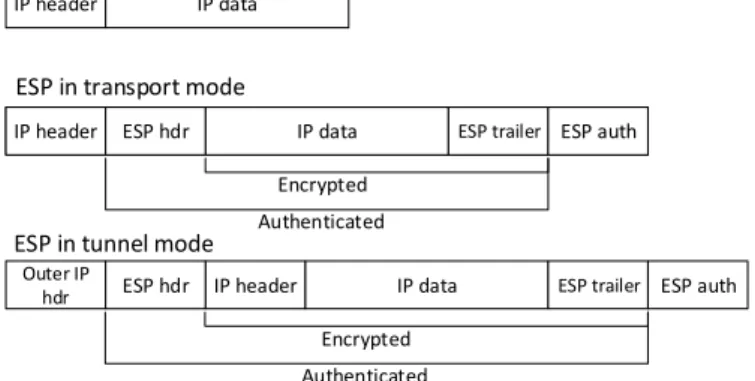
Internet Protocol Security (IPsec) is network protocol suite that protects communication over IP protocol. Its subprotocol ESP (Encapsulating Security Payload) provides confidential-ity, integrity and authenticity of transmitted data.
IP header IP data
IP header ESP hdr IP data ESP trailer ESP auth IP header ESP hdr IP data ESP trailer ESP auth
Outer IP
hdr ESP hdr IP header IP data ESP trailer ESP auth
Original packet
ESP in transport mode
ESP in tunnel mode
Encrypted Authenticated
Encrypted Authenticated
Fig. 1. IP packet secured with ESP protocol (transport and tunnel mode of operation). Source:amaranten.com
SPD
SPD
SAD
IPsec
IPsec
SAD
IKE
IKE
SA
IPsec module 1 IPsec module 2
Fig. 2. Architecture of IPsec system. Source:codeidol.com
Tunnel operation mode (fig. 1) allows for creation of VPN networks. Original packet must be properly padded, so it can be encrypted with block cipher (total message length must be multiple of cipher’s block length). Padding contains also part of the ESP protocol header (ESP trailer). Then packet is ciphered and ESP header (ESP hdr) is added. It consists of two fields: Security Parameter Index and Sequence Number. First one is identificator of SA (Security Association) — logi-cal connection between two network devices with set of cryp-tographic attributes shared by them (e.g. cipher key) and the
latter is countermeasure against replay attacks. At the end ICV (Integrity Check Value) is appended (ESP auth, e.g. keyed-hash Message Authentication Code – HMAC hash). After recalculation of this value integrity and authenticity of the packet can be verified. Finally, outer IP header is attached.
Fig. 2 presents the architecture of IPsec system. Security Policy Database is reflection of corporate security policy. SPD stores selectors (e.g. IP addresses, port numbers, etc.), which are used by gateway to decide, whether (and possibly how) each particular packet should be protected. Security Association Database stores information necessary to secure packet (e.g. encryption key). Internet Key Exchange module is responsible for negotiation and automatic setup of new safe channels (Security Association). Module marked as IPsec per-forms all cryptographic operations and packet encapsulation.
There is a variety of available IPsec solutions.Open source software implementations are suitable only for private use (e.g. Linux OpenWRT distribution [1], designed for home routers, which offers throughput of the order of several dozen Mbit/s). More efficient solutions require significant hardware resources (over a dozen processing cores) to achieve maximal throughput of 1 Gbit/s (strongSwan project [2][3]). Commer-cial implementations often use hardware support (e.g. Intel IPsec library designed for Intel Architecture processors with extended instruction set [4]). These solutions offer higher throughputs (of the order of several Gbit/s, [5][6]), but are expensive. There are commercial implementations of IPsec using FPGAs [7] or GPUs [8], but they don’t provide all IPsec features (e.g. IP traffic header processing or any IPsec database functions).
III. PROTOTYPEDESIGN
Original goal of this paper authors was to develop IPsec gateway, that implements all stages in FPGA and maximizes benefits of hardware packet processing, in contrast to other solutions that use hardware only for critical functions acceler-ation. Solution was split into hardware data plane and software control plane (including IKE module).
A prototype of IPsec gateway was designed [9] and its analysis allowed to elaborate guidelines for next generation product and generic efficient data streams processing archi-tecture.
A. Prototype Implementation
Fig. 3 presents the scheme of packet-securing part of the design (AST is abbreviation of AXI4-Stream interface). After packet reception in Ethernet controller and when data link layer header is stripped, pure IP packets are moved to sim-ple security policy controller. Pearson’s hash is calculated from IP header selectors, which is key in SPD database and allows to find apropriate records. This module determines whether data must be secured or can be transmitted through bypass path. The entire data securing process is carried out in IPsec outbound module. Subsequent processing steps are: SAD database lookup to fetch particular SA attributes, ESP encapsulation and DES encryption. The last step is SHA1-based HMAC calculation and packet is stored in FIFO until it is appended.
B. Prototype Performance Analysis
Prototype of IPsec gateway was tested with Terasic DE2-70 developer board equipped with Altera’s Cyclone II FPGA. Maximum clock frequency of the design was 86.72 MHz with 20% FPGA logic utilization.
Rb M bit s = 8·Nhpacketbytesi Mhpacketcyclesi ·F[M Hz] (1)
Using formula 1, whereN– size of the packet,M– number of cycles necessary for packet processing,F– maximum clock frequency of the design, throughput of the IPsec gateway for several packet lengths was computed (table I).
TABLE I
IPSECGATEWAYPROTOTYPEPERFORMANCE
Packet size [byte] Cycles/packet Rb[Mbit/s]
64 520 85.39
240 784 209.70
1500 2682 437.44
The correctness of prototype operation was verified with functional simulation and tests including packet generator and sniffer (Ostinato and Wireshark respectively). Prototype
64
out_AST64
in_AST policy controller IPSec_outbound bypass_AST ESP encapsulation DES encryption HMAC SHA1 Security Policy Database Security Association Database FIFO FIFOperformance analysis allowed to identify three key elements critical for throughput increase.
The main ”bottleneck” of the prototype is the module responsible for HMAC hash calculation. HMAC algorithm requires that SHA-1 digest is computed twice — for 240-byte IP packet it takes 86% time of its processing (685 cycles of total 794).
Another problem is the design of security processor — IPsec functions are divided between security policy controller and complex module performing all other operations. During HMAC hash calculation stage, which is the longest one in the whole process, resources responsible for IP and ESP encapsulation or data encryption remain unused.
On the other hand, low FPGA logic utilization (20%) of small by today’s standards Cyclone II FPGA allows for ap-plication of hardware optimization methods, such as pipelining and parallelization of the processing.
IV. IPSECGATEWAY2.0
The prototype analysis became the basis for development of new hardware IPsec gateway architecture. Advanced hardware optimization methods were applied for its implementation, leading to increase in processing speed and better logic uti-lization (fig. 4). policy controller IP & ESP encapsulation, SAD access k x DES-ECB l x DES-CBC m x AES-CBC n x AES-CTR p x HMAC SHA-1 q x HMAC SHA-256 FIFO & switch FIFO & switch FIFO & switch FIFO & switch FIFO & switch i x j x
Fig. 4. New IPsec gateway concept
As it was mentioned in section II, processing of ESP proto-col consists of several suboperations that can be performed independently. The only requirement is that they must be subsequent for a particular packet, but couple of packets can be processed simulatenously. The IPsec functions were therefore divided into several sections of the design. What is more, every section can contain many modules implementing a specific stage of processing, working in parallel. Sections are separated with FIFO queues and round robin switches, which distribute packets between modules in particular sec-tion. As a result, even more packets can be processed at the same time. The utilization of switches enables controlling the load of processing elements in given section. Increasing the number of modules calculating the most time-consuming HMAC resulted in throughput increase. Simplified applica-tion of many different cryptographic algorithms (e.g. several ciphers in various modes in ciphering section) is also great advantage of presented architecture.
A. Internal Packet Header
New architecture concept allowed to vastly increase throughput of the IPsec gateway, however a problem of sharing Security Association attributes among modules in particular sections arose. In the prototype (fig. 3) Security Association Databaseis accessed by one complex module, which performs also all other IPsec functions, but in IPsec gateway 2.0 packet processing is distributed. Fetching SA attributes in every single module would be huge load for the database and would be extremely inefficient. Therefore it was decided that database accesses will be performed in separate gateway section and all the information will be transmitted alongwith the packet. Fig. 5 presents structure of internal packet header before given modules in IPsec gateway sections, which is transported using TUSERsideband signal of AMBA AXI4-Stream [10] interface together with IP data.
SAD row number routing header DES/AES key IV Initial HMAC hash 64 128 SAD controller no cipher DES cipher AES-CBC cipher AES-CTR cipher HMAC SHA-1
Fig. 5. Internal packet header structure for various cryptographic algorithms Packet, which was directed for securing in security pol-icy controller, has a pointer to specific Security Association Database row. After SAD access section all headers contain routing field with information about next destination modules (e.g. packet must be ciphered in AES-CBC module and ICV at HMAC-SHA1 module must be appended). Packets before encryption section (except the situation when no cipher is ap-plied) have ciphering key and other information depending on cipher operation mode [11][12] attached. Fig. 5 shows also how the internal header is changed between sections — after ciphering section all data necessary for encryption are stripped and before HMAC section header contains only initial HMAC hash values.
B. Packet Switch
Packet switch is the crucial element of this high-performance and configurable architecture. It relays packets basing on information from internal header and works as load-balancer.
Concept of packet switch implementation is illustrated in fig. 6. Module has N inputs connected to long FIFOs — these are actual packet buffers. FIFOs connected toM outputs are short, because they must buffer only one packet, which is currently being processed by destination module.
Switch contains also two internal sets of FIFOs — queue andtype, respectively. First one allows to register all incoming packets with given destination address (in fact destination module type). Number of output connected to module of given
FIFO FIFO FIFO FIFO FIFO FIFO N inputs M outputs type & busy signals 12 8b AX I4 -S tr e am FSM 1 FSM 2 FSM 3 queue FIFOs type FIFOs
Fig. 6. Packet switch scheme
type, which is ready to process next packet, is stored in the second FIFO set.
Finite-state machine 1 (FSM1) controls queue FIFO set. It periodically checks input FIFOs and whenever one contains valid data, destination module type is read fromrouting header and number of this input is written intoqueueFIFO assigned to this type.
FSM3 is responsible fortypeFIFO set. It periodically reads typeandbusycontrol inputs and whenever destination module signalizes its availability, number of this output is written into typeFIFO assigned to this type.
The most important function is performed by FSM2. It mon-itors outputs ofqueueFIFO set and when it finds valid data, it checks appropriate FIFO fromtype set (where information about availability of desired destination module is stored). If free resource is found, FSM creates connection between input and output and packet is transmitted.
Routing headermay be also potentially used to distinguish between traffic classes within the design. Some modules in given section can be designated only to process high-priority traffic (e.g. part of AES-CBC encryption modules). Seperate type identifier must be assigned to them and then it must be included inrouting headerof high-priority packets.
C. HMAC-SHA1 Module Optimizations
In order to improve performance of IPsec gateway, opti-mizations of individual modules were also performed. Special attention was devoted to HMAC-SHA1 module, because its efficiency was the crucial processing speed curtailment in the prototype. Fig. 7 presents HMAC algorithm [13].
SHA-1 hash is calculated from IP packet with prepended i key pad value. String of bits is split into 512-bit blocks, which are processed individually by hash algorithm. In the second stage, o key pad value is prepended to previously calculated hash and the whole procedure is repeated. Finally, 160-bit HMAC hash is obtained, ready to be appended to the secured packet.I key padando key padblocks are the result
i_key_pad
IP
HASH1
o_key_pad
HASH2
= HMAC
SHA1
SHA1
512
Fig. 7. HMAC-SHA1 algorithm scheme
of XOR operation performed on the key and two constants defined in RFC 2104 [13].
The same key is used for all IP packets being secured by one SA channel. This means that SHA-1 hashes of blocks i key pad ando key padcan be calculated in advance, right after SA negotiation process and stored inSecurity Association Database instead HMAC key. SHA-1 submodule in HMAC-SHA1 processor has only to be initialized with these precal-culated values during ICV calculation — they are included in internal packet header (fig. 5). This optimization shortens the HMAC calculation by 160 clock cycles (processing time of two 512-bit blocks in SHA-1 algorithm before further optimizations – in IPsec gateway prototype).
at-1 bt-1 ct-1 dt-1 et-1 at bt ct dt et at+1 bt+1 ct+1 dt+1 et+1 ROTL5 ROTL30 ft ROTL5 ROTL30 ft+1 + + + + + + + + Kt+1 Wt+1 Kt Wt at-1 bt-1 ct-1 dt-1 et-1 at+1 bt+1 ct+1 dt+1 et+1 ROTL5 ROTL30 ft ROTL5 ROTL30 ft+1 + + + + + + + + Kt+1 Wt+1 Kt Wt
Fig. 8. SHA1 algorithm unfolding – critical path problem. Based on: [15] Another important task is reduction of time required for 512-bit block processing in SHA-1 algorithm [14]. Unfortu-nately, hardware algorithm’s loop unrolling (e.g. calculation of 2 of 80 rounds in one clock cycle) results in the extension of the design’s critical path (fig. 8), because extra addition must be performed during the same clock cycle. This leads to the decrease of design maximum frequency.
The solution of this problem was proposed in paper [15]. SHA-1 algorithm was modified by adding new variables — some calculations can be moved one round earlier than in unmodified algorithm, because their inputs are already known (values derived from previous round). That way extra addition can be avoided when unrolling the algorithm’s loop. Imple-mentation of the improved algorithm decreased the time of the 512-bit block processing to 40 clock cycles (from the
initial 80) without causing a drop in the design’s maximum frequency.
D. Other Architecture Optimizations
The width of the internal bus was increased from 64 to 128 bits (size of the AES block) in order to improve the performance. Two parallel DES pipelines (64-bit width) were placed in DES-ECB ciphering modules.
The use of many parallel processing cores created a problem in providing access to Security Association Database. To solve this, appropriate arbiter system was designed. Moreover, the accesses to the database were moved to a separate clock domain, because the DDR memory can usually be clocked with much higher frequency than other design parts.
V. PERFORMANCEANALYSIS
The design was tested with new Terasic DE5-Net developer board equipped with Altera’s Stratix V FPGA. Synthesis of the IPsec gateway in various configurations (with varying number of particular modules in the gateway sections) was conducted. Table II presents synthesis results for DES configurations. In the Configuration column, numbers of security policy controllers, SAD controllers, ciphering modules and HMAC modules in every section were listed respectively.
TABLE II
DESIGNIMPLEMENTATIONRESULTS FORDES CONFIGURATIONS
Configuration Fmax[MHz] Logic utilization
4/4/4/4 102.79 16%
4/4/4/8 104.04 20%
8/8/8/16 100.65 38%
The same throughput estimation method as in the prototype was used to compute the throughput of every configuration. It must be noted that benefits of the new architecture are visible when packet stream is being processed. In tables III, IV and V, throughput (Mbit/s) for miscellaneous packet streams is presented.
TABLE III
THROUGHPUT FOR64-BYTEPACKETS
Configuration Count of packets in stream
16 32 64 128
4/4/4/4 1137.91 1253.06 1319.84 1355.97 4/4/4/8 1691.06 2029.28 2254.75 2387.38 8/8/8/16 1940.06 2780.86 3550.16 4120.05
TABLE IV
THROUGHPUT FOR240-BYTEPACKETS
Configuration Count of packets in stream
16 32 64 128
4/4/4/4 2363.55 2526.17 2616.16 2663.61 4/4/4/8 3699.20 4342.54 4756.11 4979.33 8/8/8/16 4218.24 5784.79 7103.89 8018.07
TABLE V
THROUGHPUT FOR1500-BYTEPACKETS
Configuration Count of packets in stream
16 32 64 128
4/4/4/4 3239.63 3403.22 3478.30 3526.33 4/4/4/8 6139.47 7168.50 7732.62 8081.76 8/8/8/16 6185.03 7975.65 9291.33 10227.44
Similar tests were conducted for IPsec gateway using AES block cipher in CBC mode, which is more advanced than DES. Because the most time-consuming part in this configuration is the ciphering process, the number of ciphering modules in section was increased. Table VI presents synthesis results for AES configurations, while design throughput for miscel-laneous packet streams is shown in tables VII, VIII and IX.
TABLE VI
DESIGNIMPLEMENTATIONRESULTS FORAES CONFIGURATIONS
Configuration Fmax [MHz] Logic utilization
4/4/6/4 94.07 27%
8/8/12/8 97.98 34%
TABLE VII
THROUGHPUT FOR64-BYTEPACKETS
Configuration Count of packets in stream
16 32 64 128
4/4/6/4 830.411 973.01 1064.39 1116.84 8/8/12/8 1254.14 1658.37 1976.98 2187.06
TABLE VIII
THROUGHPUT FOR240-BYTEPACKETS
Configuration Count of packets in stream
16 32 64 128
4/4/6/4 1711.98 1990.24 2166.29 2266.53 8/8/12/8 2537.90 3355.57 4056.53 4424.76
TABLE IX
THROUGHPUT FOR1500-BYTEPACKETS
Configuration Count of packets in stream
16 32 64 128
4/4/6/4 2598.65 2755.95 3032.10 3076.89 8/8/12/8 3362.10 4580.40 4961.40 5518.80
VI. POSSIBLEAPPLICATIONS OFDEVELOPED ARCHITECTURE
Hardware acceleration of data processing is widely used nowadays and therefore there are many possible application areas of presented architecture. Authors discuss some of them. A. Intrusion Detection/Prevention System
Intrusion Detection System is a device that monitors network for malicious activity (using signature-based and
anomaly-based methods) and alarms network administrator whenever something suspicious is detected. Intrusion Preven-tion System is extended version of IDS — besides standard functionality, it is capable of blocking detected attacks. Net-work traffic is split into flows to allow its analysis. Each of them is identified with set of values (e.g. IP address, port numbers, data from application layer headers, etc.).
IP1 IP2 IP3 TCP1 TCP2 UDP1 TCP3 TCP1 TCP2 TCP2 Other protocol layer Some protocol layer Mem ctrl Mem ctrl Mem ctrl Mem ctrl Mem ctrl Mem ctrl Mem ctrl Control plane Filter Filter Filter Filter Filter Filter Filter Alarm
Fig. 9. Block diagram of Intrusion Prevention System
Concept of IPS implementation is illustrated in fig. 9. Stages of data processing were divided into sections as in IPsec gate-way. At first packets are sorted in several layers corresponding to network protocol stack, in order to create group of flows that share some common features. This divides main task to subproblems and moreover allows for load balancing of subsequent section (Memory controllers), which is responsible for counting packets belonging to given flows and storing this information in databases. Software control plane analyzes gathered data and should detect possible threats. If necessary it alarms network administrator (IDS responsibility), but also configures set of packet filteres at the end of the device to prevent malicious packets from entering the network. B. Wireless Communication
Another area, where presented architecture could be used, is wireless communication. Radio channel characteristic and its high variability enforces application of various checksums and forward error correction methods along with adaptive coding and modulation.
Fig. 10 presents simplified, generic diagram of wireless transmitter (based on [16]). Multiple video streams can be data to transmit. At first stream configuration must be performed — initial configuration is read from the database and can be modified by device control plane depending on radio channel condition (ACM). In subsequent sections CRC is calculated and redundant bits are added (there can be more than one FEC
M ul ti pl e si gn al s our ce s St re am co nf igu ra ti on . Control plane CRC 8 16 32 FEC1 BCH LDPC ... FEC2 BCH LDPC ... Constell ation mapping QPSK 8PSK 16APSK 32APSK … M odu la ti on Adaptive Coding and Modulation
Fig. 10. Block diagram of simplified wireless transmitter
layer). At the end constellation mapping is done and packet is transmitted.
VII. CONCLUSION
This paper presents high-performance and configurable FPGA architecture for data streams processing and process of its formation during hardware implementation of IPsec gateway in FPGA. Thanks to the use of advanced designing methods and the optimization typical for digital circuits imple-mentation, high processing speed was achieved. Created device can compete with commercial IPsec solutions, especially these implemented in FPGA [7]. Architecture of this design is strong basis for future hardware accelerators implementations.
REFERENCES
[1] OpenWRT project webpage, IPsec performance, accessed 26.03.18, https://wiki.openwrt.org/doc/howto/vpn.IPsec.performance
[2] strongSwan project webpage, accessed 26.03.18, https://www.strongswan.org/
[3] Klassert Steffen,Parallelizing IPsec, https://www.strongswan.org/docs/ Steffen Klassert Parallelizing IPsec.pdf, 2010
[4] Intel Corporation, Fast Multi-buffer IPsec Implementations on Intel Architecture Processors, 2012
[5] Cisco Systems, Inc.,Cisco IPsec and SSL VPN Solutions Portfolio, 2008 [6] Juniper Networks,Security Products Comparison Chart, 2015 [7] Helion Technology Limited,IPsec ESP IP Core for FPGA – Product
Brief, accessed 26.03.18, http://www.heliontech.com/ipsec.htm [8] Sangjin Han, Keon Jang, Kyoung Soo Park, Sue Moon,PacketShader: a
GPU-accelerated Software Router, http://shader.kaist.edu/packetshader, 2010
[9] Mateusz Korona, Implementation of IPsec protocol suite using field-programmable devices, bachelor thesis, 2015
[10] ARM,AMBA 4 AXI4-Stream Protocol Specification, 2010
[11] Frankel S., Glenn R., Kelly S., RFC-3602, The AES-CBC Cipher Algorithm and Its Use with IPsec, 2003
[12] Housley R., RFC-3686, Using Advanced Encryption Standard (AES) Counter Mode With IPsec Encapsulating Security Payload (ESP), 2004 [13] Krawczyk H., Bellare M., Canetti R., RFC-2104, HMAC:
Keyed-Hashing for Message Authentication, 1997
[14] Eastlake D. 3rd, Jones P., RFC-3174, US Secure Hash Algorithm 1 (SHA1), 2001
[15] Eun-Hee Lee, Seok-Man Kim, Chungbuk National University, De-sign of High Speed SHA-1 Architecture Using Unfolded Pipeline for Biomedical Applications, accessed 26.03.18, http://www.iiis.org/ CDs2009/CD2009SCI/SCI2009/PapersPdf/S231IM.pdf
[16] ETSI, EN 302 307 v. 1.1.2,Digital Video Broadcasting (DVB); Second generation framing structure, channel coding and modulation systems for Broadcasting, Interactive Services, News Gathering and other broad-band satellite applications, 2006

![Fig. 5 presents structure of internal packet header before given modules in IPsec gateway sections, which is transported using TUSER sideband signal of AMBA AXI4-Stream [10] interface together with IP data.](https://thumb-us.123doks.com/thumbv2/123dok_us/10973474.2985384/3.892.62.436.576.752/presents-structure-internal-modules-sections-transported-sideband-interface.webp)

![Fig. 10 presents simplified, generic diagram of wireless transmitter (based on [16]). Multiple video streams can be data to transmit](https://thumb-us.123doks.com/thumbv2/123dok_us/10973474.2985384/6.892.62.435.238.578/presents-simplified-generic-diagram-wireless-transmitter-multiple-transmit.webp)
